Table of Contents
Advertisement
Owners
ManuaR
° °
_
O/l/ °
Garage
Door Opener
Modem 1 39.535t
3
CAUTION:
READ
INSTRUCTIONS
AND RULES
FOR SAFE
OPERATION
CAREFULLY_
FASTEN
THIS
MANUAL
NEAR THE GARAGE
DOOR AFTER
INSTALLATIOH.
PERIODIC
CHECKS
OF OPENER
ARE REQUIRED
TO INSURE
SATISFACTORY
OPERATIOH.
mNDIEX
Page
Features
..............
2
........................
2
You'll
...................
2
Safety
Rules
........................
3
Carton
List ....................
4
Accessories
.........................
5
Identify
Your Door Type .............
5
Assembly
.............................
6
Installation
..........................
10
Adjustment
...........................
18
Operation
of Your Opener
..........
21
Radio
.......................
22
Having
a Problem?
.....................
24
Transmitter
Schematic
..............
24
Wiring
Diagram
......................
25
Receiver
..................
25
Repair
Parts,
Rail Assembly
..........
26
Repair
Parts,
Installation
...........
26
Repair
Parts,
Chassis
Assembly
....
27
How
to Order
Repair
Parts .............
28
...........
28
Sears
......................
28
Advertisement
Table of Contents

Related Manuals for Craftsman 139.53513


Summary of Contents for Craftsman 139.53513
-
Page 1: Table Of Contents
Owners ManuaR ° ° O/l/ ° mNDIEX Page Features of Your Opener ....Garage Door Opener Specifications ......You'll Need Tools ....Modem 1 39.535t Safety Rules ......Carton Check List ....Accessories ......Identify Your Door Type ..... Assembly ...... -
Page 2: Of Your Opener
FEATURES OF YOUR OPENER 6. Digital Radio Controls: 19,683 codes from which to 1. Opener Lights: Turn on and off automaticaflywith choose Can be changed easily by the owner 4-1/2 minute illumination for your safety and con- venience Provide constant light when Work Light 7.3-Channel Transmitter:... - Page 3 THIS SAFETY ALERT SYMBOL MEANS CAUTION -- PERSONAL SAFETY OR PROPERTY DAMAGE IN" STRUCTION,, READ THESE INSTRUCTIONS CAREFULLY, THIS GARAGE DOOR OPENER IS DESIGNED TESTED TO OFFER REASONABLY SAFE SERVICE PROVIDED IT IS INSTALLED OPERATED tN STRICT ACCORDANCE WITH FOLLOWING SAFETY INSTRUCTIONS, FAILURE...
-
Page 4: Check List
CARTON CHECK LiST SEARS has packaged your Garage Door Opener in two cartons THE RAILASSEMBLY CARTON CONTAINS: three-piece rail, two hanging straps, straight door arm section* and rail assembly hardware THE OPENER CARTON CONTAINS: Header Bracket* Opener Chassis Wall Control 4-Strand Bell Wire* Plastic Light... - Page 5 Acc÷ssGries Sears offers many useful accessories for your garage door open er They are illustrated below with Sears stock num- bers and descriptions., EXTRA TRANSMITTER: Includes visor clip 5371 5370_/C._ _r_/_ OUTDOOR KEY SWITCH: Opens the garage door automatically from outside when transmitter is not handy...
- Page 6 AssembUy TO AVOID INSTALLATION DIFFICULTIES, DO NOT RUN THE GARAGE DOOR OPENER UNTIL YOU HAVE COMPLETED STEP 8, PAGE ! 5. STE P 1 Assemble reoRa,_ Attach Cabl_ P.,_yBr_okot , ,=_==,,,,,= ,=, ,,,= ..TEE RAIL BACK (TO CHASSIS) CA UTtON: Do not tighten the lock nuts until bolt...
- Page 7 Assembmy connect Trolley & Attach Chain Retainer Bracket .., _,_,,u,, As a temporary stop, insert a screwdriver into Tee rail as shown° Siide the inner trolley onto the Tee rail, as shown, until it is firmly against the screw- driver Slide the outer trolley onto the Tee rail until it...
- Page 8 AssembBy DO NOT REMOVE CHAIN AND CABLE FROM DIS- PENSER CA RTON. Masle_ Detach cable from side of carton and fasten to tro!ley with a master link from coin envelope MASTER LINK PROCEDURE: Push pins of master link bar through loop of cable and hole in flat end of Cable LOOl...
- Page 9 AssembRy STEP 5 tighten the Chain and Cable CAUTION: Keep chain from twisting as nuts turned, PROCEDURE: Thread inner nut along shaft toward Inner Outer trolley Tighten chain and cable by turning outer nut in the same direction as shown, Chain is properly tightened when it is approximately...
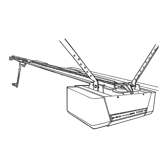
- Page 10 installation Completed installations of header bracket, door bracket and door arm (depending on door type) are shown below, The header bracket supports the front end of the Tee rail. The door bracket connects door arm to trolley IT iS RECOMMENDED THAT THE OPENER BE INSTALLED 7 FEET OR MORE ABOVE THE FLOOR...
- Page 11 nsta ation THE HEADER BRACKET MUST BE RIGIDLY FASTENED TO THE HEADER WALL OR CEILING. REINFORCE WALL OR CEILING WiTH 2x4 IF NECESSARY, I NSTALLATION Locate height for header bracket by opening door to highest point of travel as shown. Draw a horizontal SECTIONAL DOOR AND...
- Page 12 Installation STE P 3 Attach Tee Rail to Header Bracket PROCEDURE: Position opener chassis on garage floor below door and header brackets. Use packing material base to protect cover NOTE: To enable Tee rail to clear sectional door springs, it may be necessary to lift the chassis...
- Page 13 THE OPENER CHASSIS MUST BE ATTACHED TO A STRUCTURAL SUPPORT OF THE GARAGE Three representative installations are shown. Yours may be different. Hanging brackets should be angled to pro- vide rigid support. PROCEDURE: On EACH side of opener measure the distance from chassis to structural support...
-
Page 14: Install Wall Control
INSTALL WALL CONTROL ADDITIONAL Installation PUSH BUTTONS) OUT OFTH E REACH OF CHIL_ Flange DREN, DO NOT ALLOW CHILDREN TO OPER- WALL CONTROL TRANSMITTER° SERIOUS PERSONAL INJURY FROM A CLOS- GARAGE DOOR MAY RESULT FROM MISUSE OF OPENER° FASTEN THE CAUTION LABEL ON THE WALL NEAR... - Page 15 Bnstantation TO AVOID SERIOUS PERSONAL I N JURY FROM ENTANGLEM ENT, REMOVE ALL ROPES CON NECTED TO THE GARAGE DOOR BEFORE OPERATING DOOR OPENER° REMOVE EXISTING GARAGE DOOR LOCKS OR USE A WOOD SCREW OR NAIL TO MAKE THEM |NOPERATIME. INSTALLATION AND WIRING MUST...
- Page 16 lnstaHmation STE P ! O co..ect _oo.. 4.'r,. t o"rro.ey "" '"'" ....,:_,i,,.,,_,, ....r: _ _ J========= SECTIONAL DOOR INSTALLATION ONLY PROCEDURE: Fasten straight door arm section trolley and wedge door arm section to door bracket, as shown (A) Insert and spread acotter pin to secure each connection Lock...
- Page 17 nstaSiation STE P 11 Adjust Limits One-Piece Doors (All Only) CAUTION: To prevent damage to garage doors, the opener limits must be adjusted on ALL ONE- PIECE DOORS. Limit Adjustment settings regulate the points which door will stop when moving up or down.
-
Page 18: Adjustment
Adjustment ST'E Adjust UP and DOWN Limits The limit adjustment screws are located on the left side panel of the opener chassis as shown LIMIT ADJ USTMENT settings regulate the points at which the door will stop when moving up or down NOTE: DoorSTOPS in UP direction... -
Page 19: Controls
Adjustment $TgP 2 Aajust Force DO NOT USE FORCE ADJUSTMENTS TO COMPENSATE FOR A BINDING OR STICKING GARAGE DOOR. EXCESSIVE FORCE WILL INTERFERE WITH THE PROPER OPERATION OF TH E SAFETY REVERSE SYSTEM OR DAMAGE THE GARAGE DOOR_ Force Adjustment Controls are tocated on right side... -
Page 20: Test Safety Reverse System
Adjustment STEP 3 Test Safety Reverse System ....... " '" THE SAFETY REVERSE SYSTEM TEST IS IMPORTANT, THE GARAGE DOOR MUSTREVERSE ON CONTACT WITH A ON E INCH OBSTACLE PLACED ON THE FLOOR, FAILURE TO PROPERLY ADJ UST TH E OPENER RESULT IN SERIOUS PERSONAL... - Page 21 Operation of Your Opener CAUTION: e STARTBY READING THESAFETYRULES ON PAGE3. e READ THE OPERATING INSTRUCTIONS ON THIS PAGE CAREFULLY. o DO NOT PERMIT CHILDREN TO PLA Y IN AREA OF DOOR. e OPERATE ONLY WHEN OPENER IS PROPERLYADJUSTED AND DOOR tS tN SIGHTAND FREE OF OBSTRUCTION.
-
Page 22: Radio Controls
Rad6o Controls RECEIVER RADIO CONTROLS consist of two 3-channel trans _ mitters and a receiver The coded signal is factory preset The garage door openerwitl operate by pressing Wail Control push button or by pressing the TOP (large) transmitter push button tn addition, each transmitter... - Page 23 Radio Controls The position (% - orO) of RECEIVER code switch No. t sets the transmitter to operate from ONE of its push buttons. The positions of RECEIVER and TRANSMITTER code switches 2 through 9 set the signal code. Changing the position of only one switch makes...
-
Page 24: Schematic
Having a PtoNem? OPENER DOESN'T ACTIVATE DOOR OPENS AND CLOSES BY ITSELF 1, Have you removed all door locks and bolts? Neighbor with a Sears opener using the same code? Change your code 2,, Does the opener have electric power?. Check wati switch, fuse, etc, LIGHTS... - Page 25 I°...
- Page 26 RAIL ASSEMBLY PARTS LIST IA995 Master link kit 41B26!7 Outer trolley 41B2771 Inner trolley 12A197 Chain retainer brackel t 83B93 Tee rail-end section (each) 4t B2616 Cable pulley bracket assy (each) 41C2735 Chain and cable 2B3t3 Tee rail-center section NOT SHOWN 41A2814 Rail assy hardware...
-
Page 27: Chassis Assembly Parts List
Repair Parts Chassis AssembRy Parts List PART DESCRIPTION I KEY NO., PA RT DESCRIPTION 108D30-1 Lens (each) 3tC290 Sprocket cover 30B363 Capacitor 41 A2827 Gear and sprocket assy t 2A373 Capacitor bracket Complete with: 1 A2510 Terminai btock w/screws Spring washer 41 A2821 Motor asay w/roll... -
Page 28: Aintenance Agreements
Owners Manua HOW TO ORDER REPAIR PARTS Garage that have purchased your Sears Garage Door Opener, should need ever exist for repair parts or service, simply contact any Sears Service Door Center &nd most Sears, Roebuck stores Be sure to provide pertinent facts when...