
Related Manuals for Craftsman 139.653100


Summary of Contents for Craftsman 139.653100
- Page 1 S_ _ kL_ i _!iii_ _ _i!_ i_iiii_ i!i_:_ii_ _:_!_ _:_'::_s:_'_i SECTgOHAL D OORS ONE PIECEDOORS...
-
Page 2: Before You Start
Before You Start.,. identify your door •follow specific index for assemblyand installation Sectional D DOt One Piece Door. Jamb Hardware_ One Piece Door, No Track. Jamb One Piece Door. No Track, Pivot With Curved Track Horizontal Track° Hardware,, Hardware, ,,/_, ,, DOOR DOOR TRACK... -
Page 3: Rules For Safe Operation
Preparation THE VALUEOF YOURGARAGE DOOROPENER MAiNTAiN MAINTENANCEAGREEMENT Here is a comparative chart indicating the warranty Maintenance Agreement coverage a Sears Maintenance Agreement ....Coverage Years of Ownership ..AGREEMENT 1) Defective Parts 90 Days 2) Service to replace Warranty Sears Garage Door Openers are designed,... - Page 4 You'll Need Toels During assembly and installation of your opener, the instructions will call for use of various hand tools_ Have a stepladder handy, and those tools illustrated below: Hammer, electric drill (also 3/16" and 5/16" drill bits), screwdriver', adjustable end wrench or socket wrench kit, wire cutters, pliers and hacksaw.. Adjustable Wrench Pliers...
- Page 5 Hardware Open the hardware containers and check contents before startingF Rail Assembly Hardware Chain Retainer Bracket Master Rait Trolley Link Grease 2 Screws 3/8"'-16x7/8" 4 Lock Nuts 2 Lock Washers 4 Carriage Bolts Items in this box are for assem- 2 Nuts 1!4'°-20x 1/2'"...
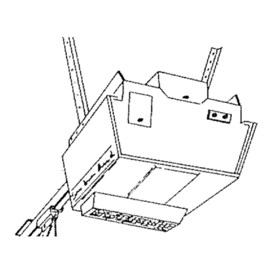
- Page 6 Assembly Reverse Switch Cover Step Open Rail Assembly Hardware Box REMOVE SPROCKET COVER FROM OPERATOR: Place op- erator on packing material to prevent scratching chassis cover. Remove sprocket cover from top of chassis by unfastening screw as illustrated. DO NOT REMOVE REVERSE SWITCH COVER, Screw...
- Page 7 Assembty 'i6x_t6 LG BOLT ATTACH ASSEMBLED RAIL TO OPERATOR: Place operator on packing material to avoid scratching cover,, Align holes motor end of Tee rail with holes in operator chassis an illustrated, For convenience, place a support under sprocket bracket Fasten Tee rail to operator with two washered...
-
Page 8: Installation
Installation Step 7 TIGHTEN CHAIN: Tighten the chain adjusting two 5/16 inch nuts on chain stud de_ignated"inner" and "outer" as illustrated,, Chain is propmty tightened when it is approxi- mately 1/2 inch above the base of the Tee rait at its midpoint Chain between idler... - Page 9 Installation POSITION THE OPERATOR: Raise operator onto a stepladder, Open the garage door,, Place a 2x4 on edge along top section door, Rest the Tee rail on the 2x4 as illustrated NOTE: A 2x4 is convenient for establishing an ideal door-to- rail distance, It is not a necessity where...
- Page 10 installation Release Arm Step Cotter _-%---- Clevis Straight DETERMINE DOOR LENGTH: Thread one end of nylon cord through red handle and secure with knot,_ Thread other end through hole in release arm of trolley, Secure with a knot Door Arm Remove plastic carrying...
- Page 11 instaJlation COD_ LABEL CAUTION: RECEIVER ADDITIONAL PUSH BUTTON SIGNAL MUST BE MOUNTED OF THE REACH CODE LABEL SMALL CHILDREN. INSTALL RADIO RECEIVER: There are installation flanges OPENER TERMINAL BLOCK at both ends of the receiver, Attach the receiver to an interior garage wall with the wood...
- Page 12 justment Step ADJUST OPENER LtMITS: Run the opener through a com- ptete up and clown cycle. Adjustments are not needed when door opens and closes completely. door does close completely, lengthen door required, A,. Run door in UP direction. If it does not open enough, limit nut adjustments are necessary.
- Page 13 ustment ADJUST DOOR FORCE: Determine that door force is not ex- cessive in down direction.. Grasp the door handle or the bottom of the door as it is about halfway through downward travel. Normally the door should reverse by this action. If it is hard to hold, or doesn't reverse, loosen...
-
Page 14: One Piece Door Installations
One Piece Door Installations One Piece Door° Jamb Hardware° Step 1 H orizonta| Track. 5/16" LOCK Highest Point WASHER ofir_ave _ INSTALL DOOR BRACKET: (Hardware in plastic ,,,_..LEADING bag will be needed in the following steps). Deter- TOP OF DOOR mine... - Page 15 One Piece Door InstaHiations POSITION OPERATOR: A One-Piece Door Without Track: Raise motor of opener a height equal to door bracket with door open. Support opener with stepladder. maximum efficiency, secure operator more than 2 inches higher than this,. B One-Piece Door With Track:...
- Page 16 One Piece Door Installations Step 8 OPENER LIMITS: (1) Using the radio controls, run trolley back to the "up" limit near motor end of unit, Disconnect electric power, Remove 4 cover screws slide cover forward from chassis illustrated_ (2) Adjustments are made by turning large plastic...
- Page 17 One Piece oor Instal Otis ADJUSTMENTS: If, after installation of opener, door does not open or close satisfactorily, follow adjustment steps 16 and 17 on Pages 12 and 13,, INSTALL LIGHT LENS: Refer to Step T8, Page 13, REMOTE INSTALLATION PROCEDURES REMOTE INSTALLATION...
-
Page 18: Radio Controls
Radio Controls SEARS DiG|TAL RADIO CONTROL PAT A PUEOFOR The coded signal in Sears Digital Radio Controls can be changed easily without the aid of a serviceman,, The only tool needed is a flat blade screwdriver Choose your own code by changing position of ON-OFF switches... -
Page 19: Parts List
TRANSMITTER RECEIVER CODE LABEL SIGNAL CODE LABEL OPENER TERMINAL BLOCK BELL WIRE i PUSH BUTTON RECEIVER TERMINAL BLOCK FLANGE Parts List PART [JESCRIPTION RECEIVER IB1436 Receiver case assy. IA1385S Receiver circuit board IAI385Y with cover (Specify S IA1492 Receiver cover TRANSMITTER IA1489 Case assembly... -
Page 20: Wiring & Specifications
Wiring & Specifications WIRING DIAGRAM 117 V AC 60Hz LINE NEUT. CONVENIENCE OUTLET(X) _,,C_r ,'¢7 I BUTTON LAMP DELAY SWITCH MOTOR ..=J CRK. fiRK, iMPULSE RELAY W/THERMAL OVERLOAD DOWN LIMIT OBSTRUC CLASS SWITCH REVERSE DISABLE LSW_TCH j 24vAC 270 .rz YEL L NOTE PARTS(X)AND(Y)ffOT... - Page 21 pair Parts Rail AssembBy 11> ji PartsList 11 _ PART DESCR IPT ION 146A19 Pin,cotter 12A129 Bracket,header 146A30 Pin,clevis,3/Sx3 133A29 Nut,3/8-16 216A26 Lockv, asher,3i8 IA452 Sprocket bracket assy. 171A88 Screw,hex,5i16xl-7/8 171AZ4 Screw,hex,3/8-16xl 183B35 Tee rail,header IA955 Trolley,outer assy. 146A21 Pin,clevis,3!Sxl-I/16 91A7 Handle,pull release...
-
Page 22: Repair Parts
Repair Parts ChassisAssemblyParts List PART f'lO. IlO, DESCRI PT _Of'i 171A183 Screw,BFx3/8 31B129 3-L L_ .__=___r5_ Cover,reverse Swi'!'Ct_ 31B127 Cover,sprocket _.__]5=._ - ,8 171A74 Screw,hex,BBx3/8 IA950 Shaft sprocket assy 216A95 Washer,shim, I/2" I .D ..1455 .... '_-"-_II _<_ ,\',Ltt 158A30 "E"... - Page 23 SAVE-A-CALL BY CHECKINGTHESE BASIC POINTS. INSTALLATION GUARANTEED BY THE INSTALLER.IF IT iS A SELF-INSTALLATION, CORRECTIONS WILL BE MADE ON A CHARGE BASIS. WHEN DOOR OPENS AND/OR CLOSES BY ITSELF: WHEN DOOR WILL OPEN WITH TRANSMITTER(S). Check pushbuttons and wiring (receiver to opener} by prod- WALL...
- Page 24 HOW TO ORDER REPAIR PARTS The Model Number' will be found on the label attached to the back of the opener.. Always mention the Model Number when requesting service or repair parts for your SEARS ELECTRONIC GARAGE DOOR OPENER° All parts listed herein may be ordered through SEARS, ROEBUCK AND CO.