Table of Contents
Advertisement
Available languages
Available languages
Quick Links
Owner"
s
anUal
N
1.5 Horsepower (continuous
duty)
3450
R.P.iVl. (no load
R.P.lVl.)
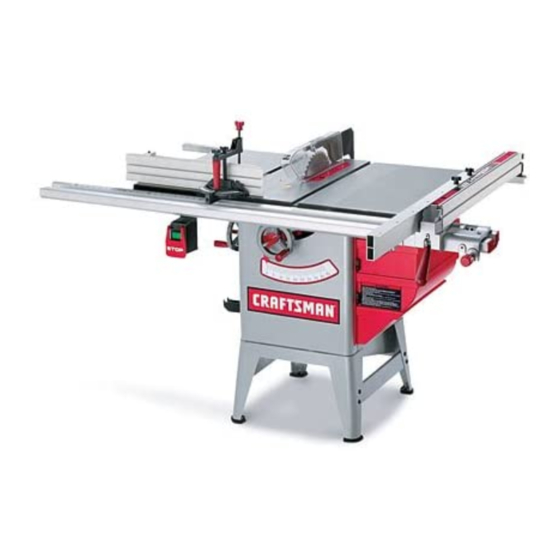
10-in. TA LE SAW
Model
No.
351.221140
®
C
US
CAUTION'.
FOR YOUR OWN SAFETY;
Read
and follow all of the Safety and
Operating
Instructions before
Operating
this Table Saw.
Customer Helpline
1-800-266-9079
Please have your Model No.
and Serial No. available.
Sears, Roebuck
and Co., Hoffman
Estates,
IL 60179 U.S.A.
Part No. OR91551
VER. 9.08
EspaSol pg. 49
Advertisement
Table of Contents

Related Manuals for Craftsman 351.221140


Summary of Contents for Craftsman 351.221140
- Page 1 Owner" anUal 1.5 Horsepower (continuous duty) 3450 R.P.iVl. (no load R.P.lVl.) 10-in. TA LE SAW Model 351.221140 ® CAUTION'. Customer Helpline FOR YOUR OWN SAFETY; Read 1-800-266-9079 and follow all of the Safety and Operating Instructions before Please have your Model No. Operating this Table Saw.
- Page 2 ONE-YEAR FULL WARRANTY ON CRAFTSMAN TOOL If this Craftsman tool fails due to a defect in material or workmanship within one year from the date of purchase, CALL 1-800-4-MY-HOME® TO ARRANGE FOR FREE REPAIR (or replacement if repair proves impossible).
- Page 3 GENERAL SAFETY INSTRUCTIONS KEEP VISITORS AND CHILDREN AWAY from the table saw. DO NOT permit people to be in the Operating a Table Saw can be dangerous if safety and immediate work area, especially when the electrical common sense are ignored. The operator must be tool is operating.
- Page 4 18. DONOTstoreanything above or nearthetool GUIDELINES where anyone might t ryto standonthetoolto EXTENSION CORDS reachit. 19. MAINTAIN YOUR BALANCE. D ONOTextend The smaller the gauge-number, the larger diameter of yourself o verthetool.Wearoil resistant rubber- the extension cord. If in doubt of the proper size of an soledshoes.
- Page 5 THIS TOOL MUST BE GROUNDED WHILE IN USE USE ONLY A 3-WIRE EXTENSION CORD THAT HAS TO PROTECT THE OPERATOR FROM ELECTRIC A 3-PRONG GROUNDING PLUG AND A 3-POLE SHOCK. RECEPTACLE THAT ACCEPTS THE TOOL'S PLUG. IN THE EVENT OF A MALFUNCTION OR BREAK- REPLACE A DAMAGED OR WORN CORD IMMEDI- ATELY.
- Page 6 It is also necessary to replace the 120 volt plug, sup- Basic precautions should always be followed when plied with the motor, with a UL/CSA Listed plug suitable using your Table Saw. To reduce the risk of injury, for 240 volts and rated current of the saw. Contact a electrical shock or fire, comply with the safety rules listed below: local qualified electrician for proper procedures to install...
- Page 7 13 DONOTusetheTable Sawas a toy.DONOTuse 27. NEVER perform layout, a ssembly or set-up workon nearor around children. the table/work a reawhen the machine is running. 28. NEVER reset t hethermal-overload buttonbefore 14. TheTable Sawis designed f orhomeuseor light commercial dutyONLY. youhaveturnedthetablesaw"OFF".
- Page 8 Anti-Kickback Fingers- Asafetydevice attached to Kickback- Whentheworkpiece is thrown back the bladeguard andsplitter a ssembly d esigned to stop towards theoperator d uringa cutting operation when a workpiece f rombeingthrown backduringa cutting the workpiece i nitially contacts thebladeor if thework- operation.
- Page 9 AVAILABLE ACCESSORIES Sears may recommend other accessories not listed in this manual. May be available at your Sears Hardware Department or see the Sears Power and Hand tool Catalog or visit See your nearest Sears Hardware Department or Sears WWW.SEARS.COM for the following accessories.
- Page 10 CONSTRUCTING A PUSHSTICK When ripping work less than 4 inches wide, a pushstick should be used to complete the feed and could easily be made from scrap material by following the pattern shown in figure 2C. Fig. 2C The Pushstick should be made of 3/4 or 1/2 inch wood or a thickness less than the width of the workpiece to be cut.
- Page 11 UNPACKING AND CHECKING CONTENTS Fig. 3-1 The table saw is a heavy machine, two people are required to unpack and lift the table saw. This table saw will require some amount of assembly. The table saw and fence is shipped in one carton. This carton also contains a box of saw parts.
- Page 12 FENCE Fig. 3-2 20.Auxiliary fence 21. Ripfenceassembly 22. Fence frontrail,right 23.Fence frontrail,left 24. Fence rearrail(2) 25.Clampknobwithspecial n ut(2) 26.Micro-Adjust assembly 27.Fencerearrailconnector 28. Frontrailendcap,right 29. Frontrailendcap,left 30.Fence frontrailalignment bar(2) MITER GAUGE Fig. 3-3 40. Miter gauge 41. Cross cut fence 42. Depth stop 43.
- Page 13 Fig. 3-4 HEX ilEAl) x I_ HSxl_ I-EX %/10"-|8 F_EX S[L'klE]r HEAD C_ SCREV HSxl.Z_ HEX SnCKIE_I" HEAD CAP NCL_EV _xl.25 I_i[]lLeND lEAD S[LF-1AP R[WJ_D _LF-l_ _[aEV i_e_n L[_CK V_HER LBC[ VA_I[R 5/16" CAI_RiA6E HEAD _V 5/16=18 X .518" Hardware packs are not identified or labeled. See hardware diagram to help in finding the correct part.
- Page 14 10. Rear rail 19. Rubber foot 1. Splitter assembly 2. Blade guard 11. Auxiliary fence 20. Blade height handwheel 12. Front rail with scale 21. Handwheel lock knob 3. Anti-kickback fingers 4. Blade 22. Fence hook 13. Micro Adjustment knob 23.
- Page 15 TOOLS REQUIRED Attach two tie bars (F) inside and between front and rear legs already attached to the cabinet with (G) The following tools are needed for assembly and align- ment. Note: Two blade wrenches and five hex wrenches eight 5/16-18 x 5/8" carriage head screws, 5/16" flat washers, 5/16"...
- Page 16 POLY-V BELT ASSEMBLY Lay a straight (C) across the saw table (D) and extension wing (E). Make sure that the front face of the extension wing (F) is flat to the front face to the MAKE CERTAIN the table saw is disconnected from main table (G).
- Page 17 Place one of the handwheels (A) onto the shaft (B) Assemble both of the fence hooks (A) to the left of the bevel shaft located on the side of the cabinet. side of the cabinet (B) using four M4 x 8mm sheet Align the groove (C) in the back of the handwheel metal screw, not shown.
- Page 18 Figure 10-3 Figure 10-5 Place the front attachment point (D) of the blade Place a square (N) onto the saw table and against guard and splitter assembly (H) down into the tool- the splitter assembly (O) behind the kickback less front attachment point (E) and the rear attach- fingers (P).
- Page 19 RiP FENCE ASSEMBLY Slide the heads of four M8 x 35mm square head screws (F), two from each end of the front rail into the front rail. Note: The front rail is still positioned upside down on the saw table. Position the screws MAKE CERTAIN the table saw is disconnected from so that they will align with the two holes in the front...
- Page 20 Figure 11-4 Figure 11-6 Slide the right side rear rail (T) onto rear rail con- nector. Assemble the right rear rail with two M8 x 25mm button head cap screws to the saw table and one M8 x 35mm button head cap screw, M8 flat Using a combination square (K), make sure the washer, M8 lock washer and M8 hex nut to the front rail (L) is level across the saw table and exten-...
- Page 21 17.Assemble t hecursor(U)to therightsideoffence AUXILIARY FENCE ASSEMBLY crossarmwithtwoM5x 16mmpanheadscrews andM5lockwashers (W).Donotcompletely t ight- enscrews. S eefigure11-7. ALWAYS position auxiliary fence at least 2-inches in 18.Aligncursorwiththescale(Z)sothatthethinblack front of the saw blade when using auxiliary fence as a line(Y)is onthesamenumber a sthedistance stop when crosscutting.
- Page 22 ON/OFF SWITCH Place the left front rail end cap (A) into the end of END CAP ASSEMBLY the front rail (B). Attach end cap to rail with two M4 x 16mm pan head self-tapping screws (C), See figure 14-2. Repeat step above to attach right side front rail MAKE CERTAIN the table saw is disconnected from end cap.
- Page 23 MITER GAUGE ASSEMBLY Figure 16-2 MAKE CERTAIN the table saw is disconnected from the power source. Figure 16-1 Slide both of the square nuts with hex socket head cap screws and flat washer (F) into the lower T-slot (G) of the cross cut fence (H). See figure 16-2. Place the thread section of the hex socket head screws into the grooves (I) of the miter gauge body.
- Page 24 BOLTING TABLE SAW TO THE FLOOR MAKE CERTAIN the table saw is disconnected from the power source. If you wish, the table saw can be permanently mounted to the floor. To attach to the floor, see instructions below. Figure 15A-1 Remove the four rubber footpads (A) from the table saw legs (B).
- Page 25 CAUTION LOCKING ON/OFF SWITCH • A separate electrical circuit should be used for your When the table saw is not in use, the "ON" button table saw. The table saw comes pre-wired for 120-volt should be locked so that it cannot be started. use.
- Page 26 Tolower the sawblade,loosen thehandwheel lock If the blade will not tilt to 90-degree, turn (counter- knob(counterclockwise) andturnthe handwheel clockwise) the set screw (C) in the left hand side of counterclockwise. Whenthesawbladeis at itsdesired the saw table until the blade can be positioned to height, t ighten thehandwheel lockknob(clockwise) 90-degrees.
- Page 27 Raise the saw blade to its highest point. Figure 20-1 Place a combination square (A) on the saw table with one edge (B) of the square against the left miter slot (C). See Figure 20A-1. Adjust the square so the rule (D) just touches the saw blade about 1 inch in from the outer diameter.
- Page 28 RIP FENCE OPERATIONS Figure 20B-1 AND ADJUSTMENTS MAKE CERTAIN the table saw is disconnected from the power source. The rip fence can be used on either side of the saw blade. The most common location is on the right hand side.
- Page 29 Figure 21A-1 Figure 21A-3 Make sure that the nylon set screws (A) and nylon glide pads (B) are in place and are not damaged, Make sure there is a consistent gap between the gouged or have sharp edges. See figure 21A-1. bottom of the fence (F) and the saw table (G).
- Page 30 ADJUSTING RIP FENCE PARALLEL: Figure 21A-5 To adjust the rip fence parallel to the miter gauge Clean and wax groove, position the rip fence (B) along the right side (C) of the right hand miter gauge groove and lock the fence. The rip fence should be parallel to the miter gauge groove.
- Page 31 REARHOLD=DOWN CAUTION It is necessary when performing special operations To minimize the amount the rear of the fence (K) such as moulding, to add wood facing (A) to one or comes off the saw table, simply flip down the rear both sides of the rip fence (B).
- Page 32 TABLE INSERT ADJUSTMENT Figure 25-1 MAKE CERTAIN the table saw is disconnected from the power source when making adjustments. Figure 24-1 Make sure switch is "OFF" and disconnect power The table insert (A) must always be level with the cord from power source. saw table (B).
- Page 33 CHANGING THE SAW BLADE Figure 26A-1 • Turn the power switch "OFF" and unplug the power cord from its power source when changing the saw blade. • USE ONLY 10-in. diameter blades with 5/8-in. arbor holes, rated at or higher than 3800 R.P.M. Figure 26-1 To adjust front splitter bracket (A), loosen the two hex socket head cap screws (B).
- Page 34 MITER GAUGE OPERATION Push in plunger and make adjustments to stop AND ADJUSTMENT screw (G) so that it touches the plunger and tighten lock nut. See figure 27-2. Recheck the positive stop angle to the saw blade. MAKE CERTAIN the table saw is disconnected from Insert the guide bar into the miter gauge groove and slide the miter gauge up to the saw blade.
- Page 35 Figure 29-2 Crosscutting requires the use of the miter gauge (A) to position and guide the workpiece (B). See figure 24-1. The use of non-Craftsman attachments and acces- sories may result in risk of injury or damage to the table saw.
- Page 36 Ripping is the operation of making a cut with the grain of the workpiece; the rip fence (A) is used to position An accessory Craftsman Fence Guide can be purchased and guide the workpiece. Since the workpiece is to assist when making narrow cuts. See "ACCESSOR- pushed along the fence, it must have a straight edge IES AND ATTACHMENTS"...
- Page 37 DADO BLADE SET Dado blades and chippers have a set to their teeth. The teeth of the dado blades and chippers must be arranged so that the set of each tooth overlaps the next tooth. The set of the dado blade (C) and chipper (D) The blade guard and splitter assembly cannot be used overlap as shown in Figure 31-3.
- Page 38 Figure 31-5 The blade guard and splitter assembly cannot be used when dadoing or molding and must be swung to the rear of the saw. Blade guard must be reassem- bled when finished. Figure 32-2 Figure 31-5, shows a typical dado operation using the miter gauge.
- Page 39 CAUTION Position thewoodfacingoverthe cutterhead w iththe cutterhead b elowthesurface ofthetable. Turnthesaw Whenmolding endgrain,themitergaugemustbe onandraisethecutterhead s lowly.Thecutterhead w ill used.Thefeedshouldbeslowed upatthe endof cutitsowngroove inthewoodfacing. thecutto prevent s plintering Inallcuts,payattention tothe grain,making the cuts inthe samedirection asthe grainwhenever p ossible. • Neverusemolding cutterhead i na bevel p osition. •...
- Page 40 LUBRICATION The table saw has sealed lubricated bearings in the Only trained personnel should perform repairs to the motor housing that do not require any additional lubrica- table saw. Contact your nearest Sears Service Center tion from the operator. for authorized service. Unauthorized repairs or replace- ment with non-factory parts could cause serious injury CLEANING...
- Page 41 TOPREVENT I NJURY TOYOURSELF o r damage tothetablesaw, t urnthe power switchtothe"OFF" position and unplug thepower cordfromthe electrical receptacle b eforemaking anyadjustments. PROBLEM LIKELY CAUSE(S) SOLUTION Motor does not Switch not pressed in far enough or switch Depress switch in 1/2 inch or make sure switch is in the start: in the "OFF"...
- Page 42 TABLE SAW MODEL NO. 351.221140 When servicing, use only CRAFTSMAN replacement parts. Use of any other parts may create a HAZARD or cause product damage. Any attempt to repair or replace electrical parts on this table saw may create a HAZARD unless a qualified service technician does repairs.
- Page 43 DUST CHUTE WELDMENT OR91168 FENCE TOP OR91179 TIE BAR 405A OR91870 OR91181 CARRIAGE HEAD SCREW 5/16-18 x 5/8" CRAFTSMAN LABEL, VERTICLE OR91169 FENCE END CAP OR90064 FLAT WASHER 5/18" 406A OR91764 HEX SOCKET SET SCREW M8 x 10turn OR90386 LOCK WASHER 5/18"...
- Page 44 104N. TABLE SAW MODEL NO. 351.221140 £ 39_(8 38(8) 37(8) 36(8) 33A(8) 102 -- ]B9(8) [88(2)
- Page 45 10=iN. TABLE SAW MODEL NO. 351.221140...
- Page 46 10-IN. T ABLE SAW MODEL NO. 351.221140 "< ,c- I-- %" \\,\_ \\\\ \\\ _ \\\ "\...
- Page 47 10=IN. TABLE SAW MODEL NO. 351.221140 502.. :;q;, { 5s0(2)_ b', ' oo_, oo_o-- !_-j...
- Page 48 e, NOTES e,...
- Page 49 anual del Proprietario 1.5 caballos de fuerza (servicio continuo) 3450 R.P.iVI. (R.P.lVI. sin carga) ESA de 1 pulg. ® Lfnea de Ayuda al Cliente PRECAUCION'. 1-800-266-9079 PARA SU SEGURIDAD PERSONAL: Lea y obedezca todas las Instrucciones Sirvase tener listo su de Seguridad y Funcionamiento antes...
- Page 50 DE UN ANO PARA HERRAMIENTA CRAFTSMAN Si esta herramienta Craftsman fallara por causa de defectos en el material o en la mano de obra en un lapso de un a_o a partir de la fecha de compra, LLAME al 1-800-4-MY-HOME®...
- Page 51 NO DEBE FORZAR LA HERRAMIENTA a realizar INSTRUCCIONES GENERALES operaciones para las que no fue diseSada. Realizara una SEGURIDAD labor mas segura y de mejor calidad si se le utiliza para El funcionamiento de una Sierra de Mesa puede resultar realizar operaciones para las que fue diseSada.
- Page 52 21. REVISE SI HAY PIEZAS DANADAS ANTES DE CADA DIRECTRICES PARA LAS EXTENSIONES USO DE LA HERRAMIENTA. Revise todos los protec- ELI CTRICAS tores cuidadosamente para comprobar que funcionan correctamente y que no estan da_ados, y que realizan Mientras menor sea el n0mero de calibre, mayor sera el sus funciones dise_adas correctamente.
- Page 53 ESTA HERRAMIENTA DEBE ESTAR CONECTADA A REPONGA CUALQUIER CORDON DANADO O GASTADO INMEDIATAMENTE. TIERRA DURANTE EL USO PARA PROTEGER AL OPERARIO CONTRA LOS CHOQUES ELC'CTRICOS. PARA LAS MAQUINAS CONECTADAS A TIERRA Y CON EN EL CASO DE UN MALFUNCIONAMIENTO O AVER|A, la CORDON DISENADAS PARA EL USO EN UN ClRCUITO conexi6n a tierra ofrece el trecho de menor resistencia para la DE SUMINISTRO CON UNA POTENCIA DE RC'GIMEN...
- Page 54 Tambi_n sera necesario reemplazar el enchufe de 120 voltios Debe observar siempre las precauciones basicas cuando suministrado con el motor por un enchufe clasificado por utiliza su Sierra de Mesa. Para reducir el riesgo de lesiona- UL/CSA como apropiado para los 240 voltios y la corriente miento, choque el_ctrico o incendio, cumple con las reglas de clasificada de la sierra.
- Page 55 17. EVlTE LOS CONTRAGOLPES haciendo Io siguiente: 29. APOYE los materiales largos o anchos correctamente. • Manteniendo la hoja afilada y libre de oxidaci6n y 30. APAGUE LA SIERRA y desench0fela de la fuente de alquitran. energia. Limpie la mesa / zona de trabajo antes de aban- •...
- Page 56 Alefriz - Muesca cuadrada en el borde del material. Goma, alquitran o resina - Residuo pegajoso y basado en la savia producido por los productos de madera. Contragolpe - Cuando el material es arrojado hacia el oper- ario durante una operaci6n de corte en el momento que el Gradacion de la hoja de la sierra - La distancia en que las material hace contacto inicial con la hoja, o si el material hace puntas de la hoja de la sierra estan anguladas hacia afuera...
- Page 57 ACCESORIOS DISPONIBLES Sears podra recomendar otros accesorios no listados en este manual. Podrian encontrarse disponibles en su Departamento de Ferreteria Sears o consulte el Catalogo de Herramientas Consulte su Departamento de Ferreteria de Sears mas Manuales y Mecanicas Sears o visite WWW.SEARS.COM cercano o el Catalogo de Herramientas EI6ctricas y de Mano para obtener informaci6n sobre los siguientes accesorios:...
- Page 58 CONSTRUYENDO UNA VARA DE EMPUJE Durante el corte a Io largo de materiales con menos de 4 pulgadas de ancho, se debe hacer uso de una vara de empuje para com- pletar la alimentaci6n. Puede construirse facilmente utilizando material descartado y siguiendo el patr6n ilustrado en la Figura 2C. Fig.
- Page 59 DESEMPACANDO Y REVISANDO Fig. 3-1 EL CONTENIDO La sierra de mesa es una maquina pesada. Se requieren dos personas para desempaquetarla y levantar la sierra de mesa. Esta sierra de mesa requerira cierta cantidad de ensamblado. Esta sierra de mesa y su guia se envian en una sola caja. Esta caja tambi_n incluye una caja de piezas para la sierra.
- Page 60 GU|A Fig. 3-2 20. Guia auxiliar 21. Ensamblado de la guia de corte a Io largo 22. Riel delantero de la guia, derecho 23. Riel delantero de la guia, izquierdo 24. Riel trasero de la guia (2) 25. Perilla de abrazadera con tuerca especial (2) 26.
- Page 61 Fig. 3-4 ©© TUERCAHEX TUERCAHEX TORNILLO DE CABEZAHEXM8 x 1.25x 25 mm TORNILLO DE CABEZAHEXM6 x 12 mm M8 x 1.25 5/16pulg.-18 TORNILLO DE CABEZAHEXM8 x 1.25x 30 mm TUERCA TUERCAHEX TORNILLO DE CABEZAHUECAHEX M5 x 2Omm CUADRADA M6 CUADRADA M5 TORNILLO DE CABEZACUADRADA M8 x 1.25x 35 mm ARANDELA PLANA ESPECIAL ©...
- Page 62 1. Ensamblado del hendidor 10. Riel trasero 20. Volante de mano de elevaci6n de hoja 11. Guia auxiliar 2. Protector de hoja 21. Perilla de cierre del volante de 12. Riel delantero con escala 3. Dedos anticontragolpe mano 4. Hoja 13.
- Page 63 HERRAMIENTAS REQUERIDAS Conecte dos tirantes de tracci6n (F) por dentro y entre las patas delanteras y traseras ya conectadas al gabinete Se requieren las siguientes herramientas para el montaje y el con (G) ocho pernos de carroceria 5/16-18 x 5/8 pulg., alineamiento.
- Page 64 MONTAJE DE LA CORREA POLY-V Coloque un alineador (C) perpendicular a la sierra de mesa (D) y al ala de extensi6n (E). AsegOrese de que la cara frontal del ala de extensi6n (F) permanezca plana hacia la cara frontal de la tabla principal (G). Ajuste el ala de extensi6n de tal manera que su superficie quede al ASEGORESE de que la sierra de mesa este desconectada mismo nivel de la tabla principal.
- Page 65 Coloque uno de los volantes de mano (A) sobre el eje de Monte ambos ganchos de guia (A) al lado izquierdo del biselado (B) Iocalizado en el lado del gabinete. La ranura gabinete (B) usando cuatro tornillos de chapa metalica (C) en el dorso del volante debe alinearse con el pasador M4 x 8 mm, no ilustrados.
- Page 66 Figura 10-3 Figura 10-5 Coloque el punto de conexi6n delantero (D) del protector de hoja y del ensamblado del hendidor (H) sobre el punto Coloque una escuadra (N) sobre la mesa de la sierra y de conexi6n delantero que carece de herramientas (E).
- Page 67 Deslice las cabezas de los cuatro tornillos de cabeza NIONTAJE DE LA GUIA DE CORTE hexagonal M8 x 35 mm (F), dos de cada extremo del riel A LO LARGO delantero, al interior del riel delantero. Aviso: El riel delantero aOn sigue posicionado boca abajo sobre la sierra de mesa.
- Page 68 Figura 11-4 Figura 11-6 12. Utilizando una escuadra de combinaciones, aseg0rese de que el riel trasero est6 nivelado con la mesa de la Usando una escuadra de combinaciones (K), aseg0rese sierra, y que las alas de extensi6n est6n por debajo del de que el riel delantero (L) est6 nivelado sobre la sierra fondo de las ranuras de la escuadra de ingletes.
- Page 69 17. Monte el cursor (U) al lado derecho de la cruceta de la ENSAMBLADO DE LA GUIA ALiXlLIAR guia con dos tornillos de cabeza troncoc6nica M5 x 16 mm y arandelas de cierre M5 (W). No apriete los tornillos del todo. Ver la figura 11-7. POSICIONE siempre la guia auxiliar al menos 2 pulgadas al 18.
- Page 70 INTERRUPTOR DE ENCENDIDO/APAGADO Coloque el tap6n de extremo del riel delantero izquierdo (A) dentro del extremo del riel delantero (B). Conecte el Y ENSAMBLADO DEL TAPON tap6n de extremo al riel con dos tornillos autoroscadores EXTREMOS de cabeza troncoc6nica M4 x 16 mm (C). Ver la figura 14-2.
- Page 71 MONTAJE DE LA ESCUADRA Figura 16-2 INGLETES ASEGORESE de que la sierra de mesa este desconectada de la fuente de energia. Figura 16-1 Deslice ambas tuercas cuadradas con el tornillo de cabeza hueca hexagonal y arandela plana (F) hacia la ranura en "T"...
- Page 72 EMPERNANDO LA SIERRA DE MESA AL PISO ASEGORESE de que la sierra de mesa este desconectada de la fuente de energia. Si Io desea, la sierra de mesa puede montarse al piso de forma permanente. Para conectarla al piso, consulte las sigu- ientes instrucciones: Fig.
- Page 73 PRECAUClON ENCLAVANDO EL INTERRUPTOR ENCENDIDO/APAGADO Debe hacerse uso de un circuito el_ctrico individual para su sierra de mesa. La sierra de mesa viene cableada de Cuando la sierra de mesa no se encuentre en uso, el antemano para el funcionamiento a 120 voltios.
- Page 74 Para bajar la hoja de la sierra, afloje la perilla de cierre del Si la hoja no se inclina a 90 grados, gire el tornillo de volante de mano (en sentido antihorario) y gire el volante de fijaci6n (C) (en sentido antihorario) al lado izquierdo de la mano en sentido antihorario.
- Page 75 Eleve la hoja de la sierra a su punto mas alto. Figura 20-1 Coloque una escuadra de combinaciones (A) sobre la mesa de la sierra con uno de los bordes (B) de la escuadra contra la ranura de ingletes izquierda (C). Ver figura 20A-1.
- Page 76 OPERACIONES Y AJUSTES DE LA GUiA Figura 20B-1 DE CORTE A LO LARGO ASEGURESE de que la sierra de mesa este desconectada de la fuente de potencia. La guia de corte a Io largo puede ser utilizada a cada lado de la hoja de la sierra.
- Page 77 Figura 21A-1 Figura 21A-3 AsegtJrese de que los tornillos de fijaci6n de nylon (A) y las almohadillas de deslizamiento de nylon (B) esten en Asegurese de que exista un espacio libre consistente sus sitios y que no esten da_adas, ranuradas o con bor- entre el fondo de la guia (F) y la mesa de la sierra (G).
- Page 78 AJUSTANDO LA GU|A DE CORTE A LO LARGO Figura 21A-5 PARALELAMENTE: Para ajustar la guia de corte a Io largo en paralelo con la Limpiar y encerar ranura de la escuadra de ingletes, posicione la guia de corte a Io largo (B) a Io largo del lado derecho (C) de la ranura de la escuadra de ingletes derecha y enclave la guia.
- Page 79 RETEN TRASERO: PRECAUCION Durante la realizaci6n de operaciones especiales, como el Para reducir al minimo la cantidad en que la guia (K) se corte de moldaduras, resulta necesario a_adir un refrentado separa de la mesa de la sierra, sencillamente vire el de madera (A) a uno o ambos lados de la guia de corte a Io ret6n posterior (L) hacia debajo de manera que quede largo (B).
- Page 80 AJUSTE DE LA PIEZA DE INSERCION Figura 25-1 DE MESA ASEGORESE de que la sierra de mesa este desconectada de la fuente de potencia. Figura 24-1 AsegtJrese de que el interruptor este "APAGADO" y desconecte el cord6n de energia de la fuente de energia. La pieza de inserci6n de mesa (A) debe estar nivelada siempre con la mesa de la sierra (B).
- Page 81 CAMBIANDO LA HOJA DE LA SIERRA Figura 26A-1 Conmute el interruptor de energia a APAGADO y des- enchufe el cord6n de potencia de su fuente de potencia mientras que efectt_a el recambio de la hoja de la sierra. SOLO UTILICE hojas con diametro de 10 pulg. y con agujeros de eje de 5/8 pulg., tasados a 3800 RPM o mAs alto.
- Page 82 OPERACION Y AJUSTE DE LA ESCUADRA Empuje el _mbolo hacia adentro y haga ajustes al tornillo de parada (G) de manera que toque el _mbolo, apretan- DE INGLETES do la tuerca de cierre despu_s. Ver la figura 27-2. Vuelva a revisar el angulo del tope positivo con la hoja de la sierra.
- Page 83 (A) para posicionar y guiar el material (B). Ver la figura 29-1. El uso de aditamentos y accesorios que no sean de Craftsman podra resultar en el riesgo de lesiones al usuario o daSo a la sierra de mesa. Figura 29-1...
- Page 84 Figure 30-2 Figura 30-1 Puede comprarse una Guia Craftsman de accesorio como ayuda cuando vaya a efectuar cortes angostos. Vea la El corte a Io largo es la operaci6n de realizar un corte en secci6n "ACCESORIOS Y ADITAMENTOS"...
- Page 85 CONJUNTO DE FRESAS ROTATIVAS Los dientes de las fresas rotativas y las astilladoras tienen gradaci6n. Los dientes de las fresas rotativas y las astillado- RANURAR ras deben estar dispuestas de tal forma que la gradaci6n de cada diente este solapada con la del pr6ximo diente. Las gradaciones de la fresa rotativa (C) y la astilladora (D) se...
- Page 86 Figura 31-5 El protector de hoja y el ensamblado del hendidor no pueden utilizarse durante el fresado o el moldurado y deben bascu- larse hacia la parte trasera de la sierra. El protector de hoja debe reensamblarse cuando haya terminado. Figura 32-2 La Figura 31-5 muestra una operaci6n tipica de fresado haciendo uso de la escuadra de ingletes.
- Page 87 Posicione el refrentado de madera sobre el cabezal de corte PRECAUClON con el cabezal de corte por debajo de la superficie de la • Durante el moldurado a contrahilo debe hacerse uso de la mesa. Encienda la sierra y eleve el cabezal de corte lenta- escuadra de ingletes.
- Page 88 LUBRICAClON La sierra de mesa tiene cojinetes lubricados sellados en la S61o personal competente debe realizar reparaciones a la carcasa del motor que no requieren lubricaci6n adicional por sierra de mesa. Comuniquese con su Centro de Servicio parte del operario. Sears mas cercano para obtener servicio autorizado.
- Page 89 Para evitar herirse a si mismo o daSar la sierra de mesa, conmute el interruptor de energia a "APAGADO" y desenchufe el cord6n de potencia del tomacorrientes antes de realizar cualquier ajuste. PROBLEMA CAUSAS POSIBLES SOLUCION Motor no arranea: 1. Interruptor no fue oprimido a suficiente profundidad Presione...
- Page 90 e, NOTAS e,...
- Page 91 e, NOTAS e,...
- Page 92 Your Home For expert troubleshooting and home solutions advice: www,managemyhome.com For repair - in your home - of all major brand appliances, lawn and garden equipment, or heating and cooling systems, no ma_er who made it, no matter who sold it! For the replacement parts, accessories owner's manuals that you need to do-it-yourself.