Table of Contents
Advertisement
Quick Links
Product Manual
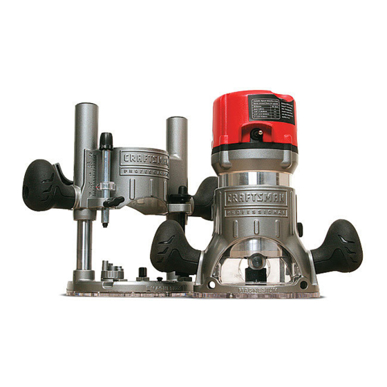
PRQFESS|ONAL
12.5 Amp, Variable
Speed,
2-114
Peak HP Router Combo
with Fixed Base, Plunge Base,
and D-Handle
Base
Model No. 320. 28084
CAUTION!
Read, understand
and
follow
all Safety
Rules and Operating
instructions
in this Manual
before
using this product.
= Warranty
= Safety
= Assembly
= Description
= Operation
= Maintenance
= Troubleshooting
Sears,
Roebuck
and Co., Hoffman
Estates,
IL 60179
www.craftsman.com
Advertisement
Table of Contents

Related Manuals for Craftsman 320.28084


Summary of Contents for Craftsman 320.28084
- Page 1 = Warranty = Safety = Assembly CAUTION! Read, understand = Description follow all Safety Rules and Operating = Operation instructions in this Manual before = Maintenance using this product. = Troubleshooting Sears, Roebuck and Co., Hoffman Estates, IL 60179 www.craftsman.com...
- Page 2 If this Craftsman professional tool fails to give complete satisfaction within one year from the date of purchase, return it to any Sears store or parts & repair center or other craftsman outlet in the United States for free repair (or replacement, if repair proves impossible).
- Page 3 We recommend a Wide Vision Safety Mask for use over eyeglasses or standard safety glasses with side shield, available at Sears Stores or other Craftsman' Outlets. 28084 Manual Revised 07-0712 Page 3...
- Page 4 WARNING: BE SURE to read and understand all instructions in this manual before using this router. Failure to follow all instructions may result electric shock, fire and/or serious personal injury. WORK AREA SAFETY • Keep your work area clean and well lit. Cluttered workbenches and dark areas invite accidents.
- Page 5 Always secure your work. Use clamps or a vise to hold the workpiece securely. It is safer than using your hand, and it frees both hands to operate the tool. • Use safety equipment. Always wear eye protection. A dust mask, non- skid safety shoes, hardhat, and/or hearing protection must be used for appropriate...
- Page 6 • inspect tool cords for damage. Have damaged tool cords repaired at a Craftsman Service Center. Be sure to stay constantly aware of the cord's location and keep it well away from the moving router. • Do not abuse the cord. Never use the cord to carry the tool or to pull the plug from an outlet.
- Page 7 • Tool service must be performed only at a Craftsman Parts and Repair Center. Service or maintenance performed by unqualified personnel could result in a risk of injury. •...
- Page 8 SAFETY RULES FOR ROUTERS CAUTION: Cutting bits coast after the router is switched off. • Hold the tool by insulated gripping surfaces (handles) when performing an operation where the cutting tool may contact hidden wiring or its own cord. Contact with a "live"...
- Page 9 1=1/4 inch. To use cutting bits with a larger diameter, install and use a sub-base with a larger diameter opening (sold separately at Sears stores or other Craftsman outlets). • Do not use large router cutting bits for freehand routing.
- Page 10 ,& WARNING: Use of this product can generate dust containing chemicals known to the state of California to cause cancer, birth defects or other reproductive harm. Some examples of these chemicals are: • Lead from lead-based paints. • Crystalline silica from bricks and cement and other masonry products.
- Page 11 Inspect tool cords periodically and, if they are damaged, have them repaired at your nearest Craftsman Service Center. Be aware of the cord location. • Always check the tool for damaged parts. Before further use of the tool, a guard or other part that is damaged...
- Page 12 _h, WARNING: If any parts are broken or missing, do not attempt to plug in the power cord or operate router until the broken or missing parts are replaced. Failure to do so could result in possibly serious injury. PARTS LIST (Fig. 1) Fig.
- Page 13 KNOW YOUR ROUTER COMBO (Fig. 2) Fig. 2 "Live Tool Indicator" Variable Speed Dial Micro Adjustment Dial Router Motor Top Cap Light Depth Indicatol Ring Power Outlet On/Off Handles with Motor Clamp Soft-Grip Coarse Adjust- Edge Guide Locking Knob Sub Base Edge Guide Mounting Slot Collet/Nut Spindle Lock...
- Page 14 PRODUCT SPECiFiCATiONS Rating 12.5 Amps No load Speed 12000-25000RPM Peak H P 2-1/4 Input 120V, 60Hz AC Collets/Nuts and Cutting Bit Shank Diameters 1/4 in., 1/2 in. Fixed Base Diameter 6 inches Plunge Base Diameter 6 -11/16 inches D-Handle Base Diameter 6 inches Sub-Base Opening (Diameter for cutting...
- Page 15 Plunge Base features fine and micro depth-rod adjustments with turret stops for precise set-ups and repetitive cutting. 8. Smooth plunge action lowers the bit into the workpiece at 90 ° for accurate cutting. 9. 3-position auxiliary handle on the D-handle base for positioning individual preference.
- Page 16 NOTE: This tool is shipped completely assembled. To change the router motor from one base to another, install or remove cutting bits, add accessories such as sawdust ejection hoods for hook-up to vacuums, or install the heavy-duty edge guide, see the following instructions.
- Page 17 DETACHABLE POWER CORD (Figs. 3, 3a and 3b) The router has a detachable power cord for easy carrying and storage. Note: Always attach the detachable power cord to the router before connecting the power cord to the power source. Before turning the router on, for the fixed base or the plunge base, connect long power cord the power outlet located on router motor top cap (See indicator label on the router);...
- Page 18 TOGGLE "ON/OFF" SWITCH (Fig. 4) Your router motor is turned "ON" and "OFF" by the toggle switch located on the top cap of the router motor. The left side of the toggle- switch (as you face it) is marked "1" for "ON" and the right side (as you face it) is marked "0"...
- Page 19 Start the router by turning on the router motor (see Fig. 14), then squeezing the ON/OFF trigger switch (see Fig. 5). To stop the router, release the ON/OFF trigger switch or push the toggle switch to the right side marked "0" ("OFF"). To lock the ON/OFF trigger switch in the "ON"...
- Page 20 14/4-inches. use cutting bits with a larger diameter, use a sub-base with a larger opening, sold separately at Sears stores or other Craftsman outlets. WARNING: When using router cutting bits with a cutter diameter larger than 1-1/2 inches, always have the speed dial set at number 1 or 2.
- Page 21 iNSTALLiNG AND REMOVING THE CUTTING BiT (Figs. 7, 8, 8a) iNSTALLiNG THE CUTTING BiT Fig. 7 1. Turn router motor off and unplug it from the Collet power source. Remove the router motor Spindle Lock from its base. NOTE: See instructions for removing and installing the router motor in the fixed base, plunge base, and D-handle base.
- Page 22 WARNING: Tighten the collet/nut securely to prevent the cutting bit from slipping. If the collet/nut is not securely tightened, the cutting bit may detach during use, causing serious personal injury NOTE: To ensure proper gripping of cutting-bit shank and minimize run-out, shank of the cutting bit must be inserted into the collet/nut...
- Page 23 CUTTING BITS Get faster, more accurate cutting results by keeping cutting bits clean and sharp. Remove all accumulated pitch and gum from cutting bits after each use. 2. When sharpening cutting bits, sharpen only the inside of the cutting edge. Never grind the outside diameter.
- Page 24 To Install Router Motor in Plunge Base (Fig. 10) 1. Turn the router motor off Fig. 10 and unplug the router from the power source. Place the plunge base on MotorSlot a flat surface. 3. With the back of the plunge base facing you, open the router-motor clamp...
- Page 25 5. Set the router motor upside down on its top cap with the collet/nut pointing up, and remove the cutting bit. 6. Store the router motor and base in the carry/storage case when not in use. To Remove Router Motor From Plunge Base (see Fig.
- Page 26 WARNING: Always remove cutting bits from the collet/nut when the router is not being used. Leaving bits installed could result in an accident causing serious personal injury. Three Mounting Positions For Auxiliary Handle Of D-Handle Base (Fig. 12) There are three mounting positions on D-handle base...
- Page 27 DEPTH ADJUSTMENT WiTH FIXED BASE (Figs. 13 and 14) The fixed base is designed Fig. 13 with a micrometer-fine adjustment system. When the bit is lowered to the approximate position desired (coarse setting), the system may then be micro adjusted to the precise depth desired.
- Page 28 Lock the Router Motor Clamp (A). 7. While continuing to press the Coarse Adjustment Knob (B), turn the Fine Adjustment Dial (F) until the "0" (zero) mark on Depth Indicator Ring (E) is lined up with the "1" mark on the base. Release the Coarse Adjustment Knob, making sure that the "0"...
- Page 29 PLUNGE ACTION (Fig. 15) Fig. 15 The plunge-base feature simplifies depth adjustments and allows the cutting bit to be accurately lowered into the workpiece for more precise set-ups. 1. To lower the cutting bit, release the plunge-lock lever by moving it "up" to the unlocked position.
- Page 30 Lock the Plunge-Depth Locking Lever (F). This position is now "0" (zero), the point from which further depth adjustments can be made. Rotate the depth-stop turret until the lowest step of the turret (A) is aligned directly under the Depth-Stop Rod (B) (see Fig.16).
- Page 31 Micro Adjustments with the Depth=Stop Rod and Depth=Stop Turret The Depth-Stop Rod has a Micro Adjustment Knob (G) that turns a screw inside the rod (B) to raise or lower the Depth-Stop Rod on the Turret (A) for micro-fine adjustments of the plunge depth.
- Page 32 The Depth Indicator Ring may be reset to "0" (zero) without moving the Fine Adjustment Dial. This allows the user to begin adjustments from any reference point. To Adjust Depth (Figs. 18 and 1; 1. Turn the router motor off Fig.
- Page 33 Deep Cuts (Fig. 20) Fig. 20 The proper cutting depth for each pass is always determined by the material, the cutting bit size, and the type and power of the motor. Always make several, progressively deeper cuts by starting at one depth and then making several more passes, each time increasing cutting...
- Page 34 HEAVY-DUTY EDGE GUIDE (Figs. 22, 22a and 22b) The Router Combo comes with a Heavy-Duty Edge Guide. This edge guide can be used as an aid in routing applications such as decorative edging, straight edge planning and trimming, grooving, dadoing and slotting.
- Page 35 Electronic Variable Speed Control (Fig. 23) The electronic speed control Fig. 23 feature allows router motor speed to be matched to cutter size and workpiece-material hardness for an improved finish and extended bit life. Speed changes are made by rotating the Speed Control Dial to the "LEFT,"...
- Page 36 The speed charts above indicate the relationship between the speed setting and the cutting application. Exact settings are determined through operator experience and preference, and by recommendations by the cutting-bit manufacturer. ELECTRONIC FEEDBACK CIRCUITRY Electronic feedback circuitry monitors and adjusts power in order to maintain the desired RPM for consistent performance and control,...
- Page 37 EDGE ROUTING (Figs. 24, 24a and 24b) 1. With the depth-of-cut set, Fig. 24 place the router on the edge of the workpiece, making sure that the cutter does not contact the workpiece. (With the plunge base, lock the plunge action in the DOWN position, ready to cut).
- Page 38 WARNING: Removing the cutting bit from the workpiece while it is still rotating could damage the workpiece and result in loss of control, causing serious personal injury. iNTERNAL ROUTING WiTH FIXED BASE (Figs. 25, 25a, 25b) 1. With the depth-of-cut set, tilt the router and place Fig.
- Page 39 NOTE: Making test cuts is essential with most routing applications. A test cut will give you a feel for the set-up, the router's speed, the depth of cut, and how the cutting bit reacts to the workpiece. INTERNAL ROUTING WITH PLUNGE BASE (Figs.
- Page 40 NOTE: Making test cuts is essential with most routing applications. A test cut will give you a feel for the set-up, the router's speed, the depth of cut, and how the cutting bit reacts to the workpiece. INTERNAL ROUTING WITH D-HANDLE BASE (Figs.
- Page 41 WARNING: Removing the cutting bit from workpiece while it is still rotating could damage the workpiece and result in loss of control, causing serious personal injury. NOTE: Making test cuts is essential with most routing applications. A test cut will give a feel for the set-up, the router's speed, the depth of cut, and how the cutting bit reacts to the workpiece.
- Page 42 EDGING WITH A PILOT BiT (Figs. 31 and 31a) Arbor-type bits with pilots are Fig.31 excellent for edge shaping Motor housing any workpiece edge that is straight or is curved with a curvature that is equal to or greater than the radius of the bit that is used.
- Page 43 FEEDING THE ROUTER (Fig. 32) The secrets to professional- Fig. 32 Router Feed looking routing are careful set- Direction up for the cut, proper depth- of-cut selection, knowing © the cutting bit reacts in the .-I= Rout workpiece, and the rate and Grain: direction of feed of the router.
- Page 44 DiRECTiON OF FEED =iNTERNAL CUTS (Figs. 33 and 33a) When making an internal cut, Fig. 33 such as a groove, dado, or Guide Outside slot, the edge guide, straight edge, or board guide must always be positioned on the Bit Rotation right-hand side of the router as you make the cut (Fig.
- Page 45 RATE OF FEED (Figs. 34 and 34a) The proper rate of feed Fig. 34 depends on several factors: the hardness and moisture content of the workpiece, the depth of cut, and the cutting diameter of the bit. When cutting shallow grooves in soft woods such as pine, you may use a faster rate of feed.
- Page 46 With almost no load on the motor, the cutting bit has a tendency to bounce off the sides of the cut in the workpiece, producing a cut with a rippled finish instead of clean, straight sides. CHIP SHIELDS (Figs. 35, 35a and 35b) _1_ WARNING: Always wear eye protection.
- Page 47 To remove the chip shield from the D-handle base, press inward on the tabs until the chip shield releases from the base and remove the chip shield. To attach, place chip shield in position, and flex sides while pushing it in until it snaps back into place (See Fig.
- Page 48 Dust Extraction Hood for Plunge Base (Fig. 36a) To attach the hood onto the Fig. 36a plunge base, position and secure it to the back of the base with the two screws (included), as shown in Fig. 36a. The dust extraction hood can also be installed with the hose...
- Page 49 TO ADJUST DEPTH WITH DEPTH=ADJUSTMENT WRENCH (Figs. 37, 37a and 37b) Fig. 37 NOTE: The Depth-Adjustment Wrench supplied is used to adjust the depth when the router is fixed to the router table (Model No. 320. 28180), sold separately. WARNING: Always read and follow all directions...
- Page 50 4. When the desired depth Fig. 37b of cut is set, tighten the clamping lever. The precise depth of cut can be measured with a ruler. When using the plunge base to attach the router to the router table, the bit depth can be adjusted by turning the depth rod clockwise...
- Page 51 All other parts represent an important part of the double-insulation system and should be serviced only by a qualified Craftsman service technician. WARNING: For your safety, Always turn off the switch and unplug the router motor from the power source before performing any maintenance or cleaning.
- Page 52 REPLACEMENT OF CARBON BRUSHES (Fig. 38) Replacement brush sets are Fig. 38 available through Craftsman Parts and Repair Centers. Unplug the router motor before inspecting replacing brushes. Replace both carbon brushes when either has less than 1/4-in. length of carbon...
- Page 53 Trouble Probable Cause Solution I -The router does not -Plug is not plugged into -Plug the detachable cord work the power source. into the power source. *Plug is not plugged into • Plug the detachable cord the Router socket. into the Router. •...
- Page 54 WARNING: The use of attachments or accessories that are not recommended for this tool might be dangerous and could result in serious injury. Sears and other Craftsman outlets offer a large selection of Craftsman router accessories designed for specific routing applications.
- Page 55 In addition to a wide variety bead and cove of router bits, Sears also _._<_ bead cove offers accessories such 1/2-in. as: Router tables, various 1/16-in. -_-_ classic cove & bead classic cove with bead template sets, universal router fence with lock knobs Roman ogee 1/4-in.
- Page 56 12.5 Amp / Variable Speed / 2= 1/4 Peak HP MODEL NUMBER 320.28084 The Model Number will be found on the Nameplate. Always mention the Model Number in all correspondence regarding your tool. Router Motor Unit 22J/ 241J 25"/_ 27JJ __26 28084 Manual RevisedO7-O712 Page56...
- Page 57 12.5 Amp / Variable Speed / 2=1/4 Peak HP MODEL NUMBER 320.28084 The Model Number will be found on the Nameplate. Always mention the Model Number in all correspondence regarding your tool. FIXED BASE 28084 Manual Revised 07-0712 Page 57...
- Page 58 12.5 Amp / Variable Speed / 2=1/4 Peak HP Fixed Base Router MODEL NUMBER 320.28084 The Model Number will be found on the Nameplate. Always mention the Model Number in all correspondence regarding" tool. -'--64 "---65 "---66 _---68 --70 --71 1-72 28084 Manual Revised 07-0712 Page 58...
- Page 59 12.5 Amp / Variable Speed / 2=1/4 Peak HP MODEL NUMBER 320.28084 The Model Number will be found on the Nameplate. Always mention the Model Number in all correspondence regarding your tool. D=HANDLE BASE -125 I05, -I 36 28084 ManuaLRevised 0L0712 Page 59...
- Page 60 12.5 Amp / Variable Speed / 2=1/4 Peak HP MODEL NUMBER 320.28084 The Model Number will be found on the Nameplate. Always mention the Model Number in all correspondence regarding your tool. ACCESSORIES r152 \154 28084 Manual Revised O7-O712 Page 60...
- Page 61 12.5 Amp / Variable Speed / 2=1/4 Peak HP Fixed Base Router MODEL NUM= BER 320.28084 The Model Number will be found on the Nameplate. Always mention tool's model number when ordering parts. Motor Unit 3703841000 Decorate Cover 3123313000 Transparent Cap 5610220000 Thread Forming Screw 3123278000...
- Page 62 2750839000 Rotor 5700008000 Ball Bearing 3123280000 Fan Baffle 5620040000 Screw 2822255000 LED Holder ASSY 5700056000 Ball Bearing 3420557000 Motor Housing 3550855000 Spindle Lock 5660005000 E Ring 3660174000 Stop Spring 5630179000 5630187000 Collet Nut 3550721000 Collet Fixed Base 5620041000 Screw 3320460000 Adjusting Knob 3123281000...
- Page 63 5630015000 Prevailing Torque Hexagon Nut 3700352000 Washer 5650172000 Wave Washer 5660005000 E Ring 3400189000 Lock Bolt 3123294000 Dust Bracket 5620067000 Screw 3122924000 Base Plate 5620049000 Screw Plunge Base 3123338000 Lock Cap 3123337000 Knighthead 3660312000 Spring Screw 5620032000 3123435000 i Adjusting Knob Plain Washer 5650014000...
- Page 64 5640045000 Bolt 3660254000 Torsion Spring 3420398000 Plunge Lock Lever 5650007000 Spring Washer 5620039000 Screw 5670026000 3703863000 Clamping Lever 3550577000 Mitre Lock Bolt 3703872000 Plate 5630015000 Prevailing Torque Hexagon Nut 5690138000 O Ring 5620103000 Slotted Shoulder Screw 3700078000 Wave Washer 3420570000 TurnTable 3700191000 3660274000...
- Page 65 3123530000 Cord Guard 5610106000 Tapping Screw 3120234000 Cord Anchorage 3320517000 Right Handle Cover 5610106000 Tapping Screw 5610031000 Tapping Screw 5610060000 Tapping Screw 4930004000 I Connector 3121475000 Left Power Indicator 2822388000 Internal Wire ASSY 3121424000 Right Power Indicator 4930314000 Receptacle 4930064000 Shark Teeth Terminal 5620041000 Screw...
- Page 66 Washer 3700352000 Button 3123282000 Dust Bracket 3123294000 Screw 5620067000 Base Plate 3122924000 Screw 5620049000 Accessories 5620050000 Screw 5650015000 Spring Washer 5650013000 Plain Washer 3703925000 Fence 3550588000 Guiding Rod 3700807000 Wrench 5630187000 Collet Nut 3550595000 Collet 3123286000 Vaccum Adapter 3402220000 Depth Adjusting Lever 3123344000 Chip Shield...
- Page 67 28084 Manual Revised 07-0712 Page 67...
- Page 68 Your Home For repair - in your home - of all major brand appliances, lawn and garden equipment, or heating and cooling systems, no matter who made it, no matter who sold it! For the replacement parts, accessories and owner's manuals that you need to do-it-yourself. For Sears professional installation of home appliances and items like garage door openers and water heaters.