Table of Contents
Advertisement
Available languages
Available languages
Owner's Manual
ICRnFTSMnN'I
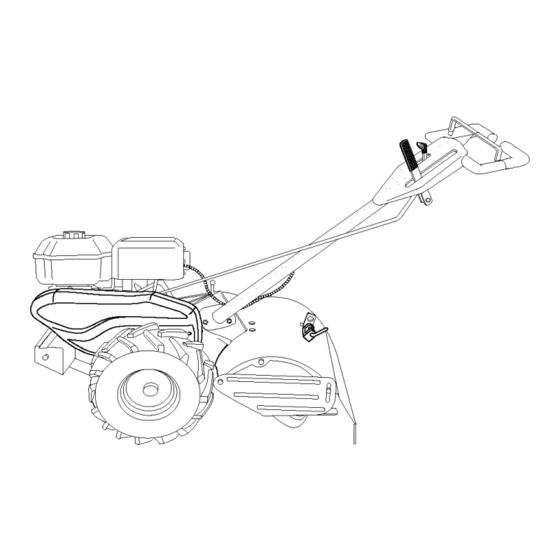
REAR TINE TILLER WITH
COUNTER ROTATING TINES
6.5 HP
17 Inch Tine Width
Model No.
917.294480
This product has a low emission engine which operates
differently from previously built engines. Before
start the
you
engine, read and understand this Owner's Manual.
IMPORTANT:
Read and follow all Safety
Rules and Instructions before
operating this equipment.
Sears, Roebuck and Co., Hoffman Estates, IL 60179
U.S.A.
Visit our Craftsman website:www.sears.com/craftsman
Advertisement
Table of Contents

Related Manuals for Craftsman 917.294480


Summary of Contents for Craftsman 917.294480
- Page 1 Before start the engine, read and understand this Owner's Manual. IMPORTANT: Read and follow all Safety Rules and Instructions before operating this equipment. Sears, Roebuck and Co., Hoffman Estates, IL 60179 U.S.A. Visit our Craftsman website:www.sears.com/craftsman...
-
Page 2: Limited Two-Year Warranty
• If this Craftsman Tiller is used for commercial or rental purposes, this Warranty applies for only thirty (30) days from the date of purchase. -
Page 3: Operation
• Use extension cords and receptacles • Never operate the machine at high as specified by the manufacturer for all speeds on slippery surfaces. Look be- units with electric drive motors or elec- hind and use care when backing. tric starting motors. •... -
Page 4: Product Specifications
PRODUCT SPECIFICATIONS CUSTOMER RESPONSIBILITIES • Read and observe the safety rules. Gasoline 3 Quarts • Follow a regular schedule in main- Capacity: Unleaded taining, caring for and using your tiller. Regular • Follow the instructions under the "Main- Oil (API-SF-SJ): SAE 30 tenance"... - Page 5 Your new tiller has been assembled at the factory with the exception of those parts left unassembled for shipping purposes. To ensure safe and proper operation of your tiller all parts and hardware you assemble must be tightened securely. Use the correct tools as necessary to insure proper tightness.
-
Page 6: Unpacking Carton
UNPACKING CARTON _CAUTION: Be careful of exposed sta- Assembly ples when handling or disposing of carton- "UP" Position ing material. Tighten handle IMPORTANT: When unpacking and ..lock lever to hold assembling tiller, be careful of exposed staples when handling or disposing of Loosen Handle Lock cartoning material. -
Page 7: Check Tire Pressure
Shift Lever INSERT CABLE CLIP Hairpin Clip ndicator • Insert plastic cable clip into hole on the Shift Rod back of handle column. Push cables into clip. Handle Column Cables Cable Clip REMOVE TILLER FROM CRATE CONNECT SHIFT 1. Adjust handle assemby to lowest 1. -
Page 8: Know Your Tiller
These symbols may appear on your Tiller or in literature supplied with the product. Learn and understand their meaning. KNOW YOUR TILLER READ THIS OWNER'S MANUAL AND SAFETY RULES BEFORE OPERATING YOUR TILLER. Compare the illustrations with your tiller to familiarize yourself with the location various... - Page 9 The operation of any tiller can result in foreign objects thrown into the eyes, which can result in severe eye damage. Always wear safety glasses or eye shields before starting your tiller and while tilling. We recommend a wide vi- sion safety mask over spectacles or standard safety glasses.
- Page 10 TURNING BEFORE STARTING ENGINE 1. Release the drive control bar. IMPORTANT: Be very careful not to allow 2. Move throttle control to "SLOW" posi- dirt to enter the engine when checking or tion. adding oil or fuel. Use clean oil and fuel 3.
-
Page 11: To Start Engine
See "TO ADJUST CARBURETOR" in the CAUTION: Alcohol blended fuels (called gasohol or using ethanol or methanol) can Service and Adjustments section of this manual. attract moisture which leads to separa- tion and formation of acids during storage. NOTE: If engine does not start, see trou- Acidic gas can damage the fuel system bleshooting points. -
Page 12: Tine Shear Pins
ADJUST WHEELS CULTIVATING 1. Place blocks under right hand side of tiller and remove hairpin clip and clevis pin from right hand wheel. 2. Move wheel outward approximately inch until hole in inner wheel hub lines up with inner hole in axle. 3. -
Page 13: General Recommendations
MAINTENANCE SCHEDULE FILL IN DATES S E V,OEO TES AS YOU COMPLETE REGULAR SERVICE Check Engine Oil Level Change Engine Oil _1,2 Oil Pivot Points Inspect Spark Arrester / Muffler Inspect Air Screen Clean or Replace Air Cleaner Cartridge Clean Engine Cylinder Fins Replace Spark Plug RH Gear Case Grease... -
Page 14: Air Filter
5. Refill engine with oil. See "CHECK _CAUTION: Disconnect spark plug ENGINE OIL LEVEl" in the Operation wire before performing any maintenance section of this manual. (except carburetor adjustment) to prevent accidental starting of engine. Prevent fires! Keep the engine free of grass, leaves, spilled oil, or fuel. - Page 15 MUFFLER __--------- Cover Knob Do not operate tiller without muffler. Do not tamper with exhaust system. Dam- aged mufflers or spark arresters could Cover -..__ create a fire hazard. Inspect periodically and replace if necessary. If your engine is equipped with a spark arrester screen as- Precleaner _,.
- Page 16 TIRE CARE Guard _CAUTION: When mounting tires, unless Nut and beads are seated, overinflation can cause Washer an explosion. (Located • Maintain 20 pounds of tire pressure. Behind tire pressures are not equal, tiller will Tire) pull to one side. •...
-
Page 17: Tine Replacement
TINE REPLACEMENT • To maintain the superb tilling perfor- mance of this machine the tines should _CAUTION: Tines are sharp. Wear be checked for sharpness, wear, and gloves or other protection when handling bending, particularly the tines which tines. are next to the transmission. If the gap A badly worn tine causes your tiller to between the tines exceeds 3-1/2 inches... - Page 18 TO ADJUST CARBURETOR ENGINE The carburetor has been preset at the Maintenance, repair, or replacement of the emission control devices and systems, factory and adjustment should not be necessary. However, engine performance which are being done at the customers ex- pense, may be performed by any non-road can be affected by differences in fuel, tem- perature, altitude or load.
-
Page 19: Engine Fuel System
Immediately prepare your tiller for storage NOTE: Fuel stabilizer is an acceptable at the end of the season or if the unit will alternative in minimizing the formation of fuel gum deposits during storage. _ktcbe used for 30 days or more. AUTION: Never store the tiller with stabilizer to gasoline in fuel tank or stor- gasoline in the tank inside a building... -
Page 20: Troubleshooting
TROUBLESHOOTING CHART: See appropriate section in manual unless directed to Sears service center PROBLEM CAUSE CORRECTION Will not start 1. Out of fuel. 1. Fill fuel tank. 2. See "TO START ENGINE" in 2. Engine not "CHOKED" properly. the Operation section. 3. - Page 21 TROUBLESHOOTING CHART: See appropriate section in manual unless directed to Sears service center PROBLEM CAUSE CORRECTION Engine 1. Low oil level/dirty oil. 1. Check oil level/change oil. overheats 2. Dirty engine air screen. 2. Clean engine air screen. 3. Dirty engine. 3.
- Page 22 Mantenimiento ..........GARANTIA LIMITADA DE DOS AI_IOS PARA LA CULTIVADORA CRAFTSMAN Por dos (2) aSos, a partir de la fecha de compra, cuando esta Cultivadora Craftsman se mantenga, lubrique y aline segSn las instrucciones para ta operaci6n y el mantenimiento en el manual del dueSo, Sears repararA, gratis, todo defecto en el material y la mano de obra.
-
Page 23: Mantenimiento
• Despu_s de pegarle a un objeto extra5o, MANTENIMIENTO Y ALMACENAMIEN- pare el motor, remueva el atambre de la bujfa, inspeccione la cultivadora cuidadosa- • Mantenga los accesorios y aditamentos de mente, para verificar si hay da_os, y repare la mAquina en buenas condiciones para el el da_o antes de volver a arrancar y operar la funcionamiento. -
Page 24: Especificaciones
ESPECIFICACIONES DEL PRODUCTO RESPONSABILIDADES DEL CLIENTE • Lea y observe las reglas de seguridad. Capacidad de 3 Cuartos • Siga un programa regular de mantenimiento, _solina: Sin plomo, regular cuidado y uso de su cultivadora. Aceite(API-SF-SJ): SAE 30 (Sobre 40°F) •... - Page 25 Su cultivadora nueva ha sido montada en la f&brica, con la excepci6n de aquellas partes que se dejaron sin montar per razones de envio. Para asegurarse que la cultivadora operar& en forma segura y adecuada, todas las partes y los arficulos de ferreteria que monte tienen que estar apre- tados en forma segura.
- Page 26 DESEMPAQUE DE LA CAJA Conjunto del mango _pRTbN posoci6n "Arriba" RECAUCION: Tenfa cuidado con las grapas expuestas cuando maneje o deseche Apriete la palanca los materiales de la caja de cart6n. de cierre del mango IMPORTANTE: Cuando desempaque y monte para la cultivadora, tenga cuidado de no estirar o enredar tos cables.
- Page 27 INSERCION DE LA ABRAZADERA Abrazadera de Horquilla CABLE lndicador de la Palanca de Cambio • Inserte la abrazadera del cable de plastico Varilla de Cambio dentro del agujero en la parte trasera de la columna det mango. Empuje los cables dentro de la abrazadera.
- Page 28 Estos s{mbolos pueden apareser sobre su cultivadora en la literature proporcionada con el pro- ducto, aprenda y comprenda sus significados. CONOZCA SU CULTIVADORA LEA ESTE MANUAL DEL DUEI_IO Y LAS REGLAS DE SEGURIDAD ANTES DE OPERAR SU CULTIVADORA Compare las ilustraciones con su cultivadora para familiarizarse con la ubicacibn de los diversos controles y ajustes.
- Page 29 La operaciSn de cualquier cultivadora puede hacer que salten objetos extraSos dentro de sus ojos, 1o que puede producir daSos graves en 6stos. Siempre use anteojos de seguridad o protecciones para los ojos antes de hacer arrancar su culti- vadora o mientras est6 labrando con 611a. Recomendamos el uso de la mascara de seguridad de visiSn amplia, para uso sobre los espejuelos o anteojos de seguridad estAnda£...
- Page 30 GIRO ANTES DE HACER ARRANCAR 1. Suelte la barra de control de la impulsi6n. MOTOR Mueva el control de la aceleraci6n a la IMPORTANTE: Tenga mucho cuidado de no posici6n de "LENTO" (SLOW). permitir que entre mugre al motor cuando Ponga el indicador de la palanca de cambio revise o aSada aceite o combustible.
- Page 31 IMPORTANTE: Cuando se opere en temperatu- 10. Permita que se caliente el motor por unos ras por debajo de 32°F (0°C) use gasolina de cuantos minutos antes de enganchar los invierno limpia y nueva para auedar a asegurar brazes. un buen arranque en clima fifo. AVlSO: A mucha altura (sobre 3000 pies) o PRECAUCION: Combustibles...
- Page 32 AJUSTE DE LAS RUEDAS PARA EL CULTIVO Ponga bloques debajo del lado derecho de la cultivadora y remueva la abrazadera de horquilla y la clavija de horquilla de la rueda del lade derecho. Mueva la rueda hacia afuera, aproximada- mente 1 pulgada, hasta que el agujero en el cubo de la rueda interior se alinee con el agujero interior en el eje.
-
Page 33: Programa De Mantenimiento
PROGRAMA MANTENIMIENTO ..s oe QUE COMPLETE Revisar el nivel de[ aceite de[ motor Cambiar el aceite del motor Aceitar los puntos de pivote lnspeccionar el supresor de[ silenciador lnspeccionar la rejilla de aire Limpiar/cambiar el cartucho del filtro de aire Limpiar las aletas del cilindro del motor... - Page 34 Despu6s de que el aceite se haya drenado _PRECAUClON: Desconecte el aiambre de compietamente, vuelva a colocar et tap6n la bujfa antes de dar mantenimiento (excepto del drenaje del aceite y apri6telo en forma por el ajuste del carburador) para evitar que el segura.
- Page 35 SILENClADOR Cubierta Tornillo de la base No opere la cultivadora sin el silenciador. No manipulee el sistema de escape. Los silenciadores o los amortiguadores de chispas daiSados pueden crear un peligro de incendio. Inspecci6nelos peri6dicamente y cAmbielos si Aletas del es necesario.
- Page 36 _q_IDADO DE LAS LLANTAS Protecci6n de la correa PRECAUCI(_N: Cuando monte las tlantas, a menos que los talones est6n asentados, si Hexagonal se inflan demasiado se puede producir una y arandela explosi6n. (Ubicadas • Mantenga 20 libras de presi6n en las Ilantas. detras de la Si la presi6n de las tlantas no es la misma, la Ilanta)
- Page 37 ParaqueestamAquina puedamantener _pl_lBIO DE BRAZOS ° unrendimiento e xcelente enel labrado, se RECAUCI()N: Losbrazos sonafilados. debenrevisar l osbrazos paraverificar s i Useguantes u otraprotecci6n cuando maneje losbrazes. est&n afilados, desgastados o doblados, especialmente losquese encuentran a l lado Si hayunbrazomuydesgastado s ucultivadora delatransmisi6n.
- Page 38 MOTOR Cable del tornillode sujeci6n El mantenimiento, la reparaci6n, o el reemplazo Cable de la de cualquier dispositivos o sistemas del control de la emisi6n, los cuates sean hechos al costo Aceleraci6n_ del cliente, pueden ser realizados por cualquier individuo o establecimiento de reparaci6n de motor.
-
Page 39: Aceite Del Motor
AVlSO: El estabilizador de combustible es una Inmediatamente prepare su cultivadora para el atmacenamiento al final de la temporada o si la altemativa aceptable para reducir a un mfnimo la formaci6n de dep6sitos de goma en et com- ,_dad no se va a usar por 30 dfas o m&s. PRECAUClON: Nunca almacene la cultiva- bustible durante el perfodo de almacenamiento. - Page 40 IDENTIFICACI(_N DE PROBLEMAS: Vea la seccibn apropiada en el manual a menos que estd dirigido a un centro de servicio Sears. CORRECCI()N PROBLEMA CAUSA No arranca 1. Sin combustible. 1. Llene el estanque de combustible. 2. Motor sin la "ESTRANGU- 2.
-
Page 41: Identificacion De Problemas
IDENTIFICACION DE PROBLEMAS: Vea la seccibn apropiada en el manual a menos que estd dirigido a un centro de servicio Sears. PROBLEMA CAUSA CORRECCION Falta de fuerza 10.Rejilla de aire del motor sucia. 10. Limpie la rejilla de aire del motor. 11 .Silenciador sucio/taponado. - Page 42 TILLER--MODEL NUMBER 917.294480 HANDLES • > \\ / 31 ' PART PART DESCRIPTION DESCRIPTION 180634 Throttle, Control STD541437 Nut, Crownlock 3/8-16 19131611 Washer 13/32 x 1 x 11 Ga. 141406 Grip, Handle 110673X Grommet, Handle 109228X Lever, Lock, Handle 150258 Handle, Assemble 127254X Bar, Drive Control Assembly...
-
Page 43: Left Side
TILLER - - MODEL NUMBER 917.294480 MAINFRAME, LEFT SIDE ... " KEY PART PART DESCRIPTION DESCRIPTION 73510500 Nut, Keps 5/16-18 126875X Rivet, Drilled STD551137 Washer, Lock 3/8 4497H Retainer, Spring STD541037 Nut, He)( 3/8-16 165501X558 Guard, Belt 170127 Shield, Inner Belt Guard 132801 Belt, V 164329... -
Page 44: Right Side
TILLER - - MODEL NUMBER 917.294480 MAINFRAME, RIGHT SIDE PART PART DESCRIPTION DESCRIPTION 102190X Tire 73970500 Locknut, Hex, Flange 5/16-18 183122X624 102332X Bracket, Reinforcement 795R Tire VaNe 102173X CounterWeight, R.H. STD551137 Washer, Lock 3/8 Engine, (See Breakdown) Bfiggs Model No. 120402-0213-E1 STD541037 Nut, Hex 3/8-16 7192J... - Page 45 TILLER - - MODEL NUMBER 917.294480 TRANSMISSION PART PART DESCRIPTION DESCRIPTION 180677 Transmission Assembly (Includes 150737 Ground Shaft Assembly Key Nos. 2-52) 143008 Bearing, Shaft, Ground Drive R.H. 180627 Gearcase, L.H. w/Bearing 106388X Spacer 0.70x 1.00x 1.150 (Includes Key No. 4) 102121X Sprocket and Gear Assembly 161963...
- Page 46 TILLER - - MODEL NUMBER 917.294480 TINE SHIELD KEY PART PART NO. NO. DESCRIPTION DESCRIPTION 73900500 Nut, Lock Hex Fig 5/16-18 Unc 102701X Grip 161415X558 Shield, Side, Outer L H. STD541037 Nut, Hex 3/8-16 8393J Pin, Stake, Depth 102156X Stake, Depth 12O00O35 74930632 Bolt, Hex 3/8-16 x 2...
-
Page 47: Tine Assembly
TILLER - - MODEL NUMBER 917.294480 TINE ASSEMBLY KEY PART PART DESCRIPTION DESCRIPTION 4459J Tine, Outer, L.H. 74610616 Bolt, Hex 3/8-24 x 1 4460J Tine, Outer, R.H. 132673 Pin, Shear 6554J Tine, Inner, LH. 132728 Assembly, Hub and Plate, R.H. 6555J Tine, Inner, R.H. - Page 48 Decal, Shift Indicator 157984 Decal, Tine, Shield, Counter Rotating Tines 120075X Decal, Warning, Rotating Tines 163094 Decal, Tine Depth Stake 162215 Decal, Tine, Shield, Warning Dom 171078 Decal, Rewind 167156 Decal, Craftsman IC 166138 Decal, lntek 186037 Manual, Owner's (Eng/Span)
- Page 49 TILLER - - MODEL NUMBER 917.294480 ENGINE, BRIGGS & STRATTON - - MODEL NUMBER 120402-0213-E1 35® 238© 15A@ 24 O 32_3_ 27 %_ I 1019LABEL,KIT, 746_ I 1058 OWNER S MANUAL I _/_'=_...
-
Page 50: Gasket Set
TILLER - - MODEL NUMBER 917.294480 ENGINE, BRIGGS & STRATTON - - MODEL NUMBER 120402-0213-E1 186_ 163_ 7..J 276 977 CARBURETOR GASKET SET 276 _ 137 _ 633Ao 121 CARBURETOR OVERHAUL KIT .._O 127_ 633 _ 633A_ 358 ENGINE GASKET SET 1022_... - Page 51 TILLER - - MODEL NUMBER 917.294480 ENGINE, BRIGGS & STRATTON - - MODEL NUMBER 120402-0213-E1 209_p 209A 663_ 2221 6161615 836 _ 190 _P 851 I 717_...
- Page 52 TILLER - - MODEL NUMBER 917.294480 ENGINE, BRIGGS & STRATTON - - MODEL NUMBER 120402-0213-E1 65 _'_ I 1036 EMISSIONS LABEL I 1005 363_ 305 _ 1095 VALVE GASKET SET 993 _ 66651...
- Page 53 TILLER - - MODEL NUMBER 917.294480 ENGINE, BRIGGS & STRATTON - - MODEL NUMBER 120402-0213-E1 PART PART DESCRIPTION DESCRIPTION 693811 Cylinder Assembly 691636 Screw (Throttle Valve) 299819 • Seal-Oil (Magneto Side) 690024 Shaft-Throttle 693643 Head-Cylinder 398185 Kit-Idle Speed 695166 °+ Gasket-Cylinder Head 691242 {3 Pin-Float Hinge 693647...
- Page 54 TILLER - - MODEL NUMBER 917.294480 ENGINE, BRIGGS & STRATTON - - MODEL NUMBER 120402-0213-E1 PART PART DESCRIPTION DESCRIPTION Gear-Idler 693610 Shield-Cylinder 692566 Retainer 690345 Screw (Cylinder Shield) 694258 690662 Nut (Flywheel) 694544 Stud (Rocker Arm) Guard-Muffler 695711 Armature-Magneto 693583 691061 Screw (Armature Magneto) 690661...
- Page 56 Get it fixed, at your home or ourst Your Home For repatr - in your home - of all major brand apphances, lawn and garden equtpment, or heahng and coohng systems, no matter who made it, no matter who sold it! For the replacement parts, accessones owner's manuals that you need to do-it-yourself.