Table of Contents
Advertisement
Available languages
Available languages
Owner's Manual
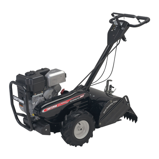
CRRFTSMRH '°
TI ETILL
DUAL ROTATI
G
850 Series
17 Inch Tine Width
TI
T
Model No.
917.297042
• EspaSol,
p. 23
This product
has a low emission
engine
which
operates
[]_]]
differently
previously
engines,
you
start
from
built
Before
the
engine,
read
and understand
this
Owner's
Manual.
IMPORTANT:
Read and follow all Safety
Rules and Instructions
before
operating
this equipment,
Sears, Roebuck
and Co., Hoffman
Estates,
IL 60179
U.S.A.
Visit our Craftsman
website:www.sears.com/craftsman
Advertisement
Table of Contents

Related Manuals for Craftsman 917.297042


Summary of Contents for Craftsman 917.297042
- Page 1 Before []_]] differently previously engines, start engine, read and understand this Owner's Manual. IMPORTANT: Read and follow all Safety Rules and Instructions before operating this equipment, Sears, Roebuck and Co., Hoffman Estates, IL 60179 U.S.A. Visit our Craftsman website:www.sears.com/craftsman...
- Page 2 If this Craftsman Tiller is used for commercial or rental purposes, this Warranty applies for only thirty (30) days from the date of purchase.
- Page 3 Use extension cords and receptacles Never operate the machine at high as specified by the manufacturer for all speeds on slippery surfaces. Look be- units with electric drive motors or elec- hind and use care when backing. tric starting motors. Never allow bystanders...
- Page 4 Gap: .080") RC12YC AGREEMENTS Congratulations on making a smart pur- CONGRATULATIONS on your purchase chase. Your new Craftsman® product of a Sears Tiller. It has been designed, designed and manufactured for years of engineered and manufactured to give you dependable operation.
- Page 5 These accessories were available when the tiller was purchased. They are also avail- able at most Sears Retail outlets and Service Centers. Most Sears Stores can order repair parts for you when you provide the model number of your tiller. ENGINE AIR FILTER GAS CAN...
- Page 6 Your new tiller has been assembled at the factory with the exception of those parts left unassembled for shipping purposes. To ensure safe and proper operation of your tiller all parts and hardware you assemble must be tightened securely. Use the correct tools as necessary to insure...
- Page 7 CONNECT SHIFT Rotate handle assembly down. Insert rear carriage bolt first, with head of Insert end of shift rod into hole of shift bolt on L.H. side of tiller and loosely lever indicator. semble Iocknut. Insert hairpin clip through hole of shift Insert pivot bolt in front part of plate...
- Page 8 These symbols may appear on your Tiller or in literature supplied with the product. Learn and understandtheir meaning. KNOW YOUR TILLER READ THIS OWNER'S MANUAL AND SAFETY RULES BEFORE OPERATING YOUR TILLER. Compare the illustrations with your tiller to familiarize yourself with location...
- Page 9 The operation of any tiller can result in foreign objects thrown into the eyes, which can result in severe eye damage. Always wear safety glasses or eye shields before starting your tiller and while tilling. We recommendstandard safety glasses or a wide vision safety mask worn over spectacles. HOW TO USE YOUR TILLER HARD TO SHIFT...
- Page 10 Move throttle control to "FAST" position IMPORTANT: Always lower the drag for deep tilling. stake when using the forward rotating tine drive. IMPORTANT: Always release drive control bar before moving shift lever into another OUTER SIDE SHIELDS position. The back edges of the outer side shields "Locked"...
- Page 11 TO START ENGINE For cold weather operation you should change oil for easier starting (See oil _CAUTION: Keep tine control in "OFF" viscosity chart in the Maintenance sec- position when starting engine. tion of this manual). When starting engine for the first time or if •...
- Page 12 TILLING HINTS CULTIVATING _CAUTION: Until you are accustomed Cultivating is destroying the weeds to handling your tiller, start actual field tween rows to prevent them from robbing nourishment and moisture from the plants. use with throttle in slow position (mid-way At the same time, breaking...
- Page 13 OUTER VIEW OF TIRE ADJUST WHEELS CULTiVATiNG Clevis Place blocks under right hand side of tiller and remove hairpin clip and clevis pin from right hand wheel. Move wheel outward approximately inch until hole in inner wheel hub lines /Pin up with inner hole in axle.
- Page 14 MAINTENANCE SCHEDULE FILL IN DATES AS YOU COMPLETE SERV,CE OATES REGULAR SERVICE Check Engine Oil Level Change Engine Oil Pivot Points Inspect Spark Arrester / Muffler Inspect Air Screen I1 # Clean or Replace Air Cleaner Cartridge Clean Engine Cylinder Fins Replace Spark...
- Page 15 Remove oil filler plug. Be careful Ai_CAUTION: Disconnect spark plug to allow dirt to enter the engine. wire before performing any maintenance Refill engine with oil. See "CHECK (except carburetor adjustment) to prevent ENGINE OIL LEVEl" in the Operation accidental starting of engine.
- Page 16 COOLING SYSTEM SPARK PLUG Your engine is air cooled. For proper Replace spark plugs at the beginning gine performance and long life keep your each tilling season or after every 50 hours engine clean. of use, whichever comes first. Spark plug , Clean air screen...
-
Page 17: To Remove Wheel
TiRE CARE Belt Guard _IiCAUTION: When mounting tires, unless Nut and beads are seated, overinflation can cause Washer an explosion. (Located Maintain 20 pounds of tire pressure. Behind tire pressures are not equal, tiller will Tire) pull to one side. Screws Keep tires free of gasoline or oil which... - Page 18 TINE REPLACEMENT To maintain the superb tilling perfor- mance of this machine the tines should ,ACAUTION: Tines are sharp. Wear be checked for sharpness, wear, and gloves or other protection when handling bending, particularly the tines which tines. are next to the transmission. If the gap A badly worn tine causes...
- Page 19 TO ADJUST CARBURETOR ENGINE The carburetor has been preset at the Maintenance, repair, or replacement factory and adjustment should not be the emission control devices and systems, necessary. However, engine performance which are being done at the customers can be affected by differences in fuel, tem- pense,...
- Page 20 Immediately prepare your tiller for storage NOTE: Fuel stabilizer is an acceptable at the end of the season or if the unit will alternative in minimizing the formation not be used for 30 days or more. fuel gum deposits during storage.
- Page 21 TROUBLESHOOTING CHART: See appropriate section in manuaJ unJess directed to Sears service center PROBLEM CAUSE CORRECTION Will not start Out of fuel. Fill fuel tank. See "TO START ENGINE" Engine not "CHOKED" properly. the Operation section. Wait several minutes before Engine flooded.
- Page 22 TROUBLESHOOTING CHART: See appropriate section in manual unless directed to Sears service center PROBLEM CAUSE CORRECTION Low oil level/dirty oil. Check oil level/change oil. Engine overheats Dirty engine air screen. Clean engine air screen. Dirty engine. Clean cylinder fins, air- screen, muffler area.
- Page 23 • Si la Cultivadora Craftsman se usa para fines de arriendo, esta garantfa se aplica solamente treinta (30) treintadias a partir de la fecha de compra. El Servicio de Garantfa esta disponible...
- Page 24 MANTENIMIENTO Y ALMACENAMIENTO Despues de pegarle a un objeto extraflo, pare el motor, remueva el alambre de la • Mantenga los accesorios y aditamentos bujia, inspeccione la cultivadora cuidadosa- la m&quina en buenas condiciones para el funcionamiento. mente, para verificar si hay daflos, y repare el daflo antes de volver a arrancar y operar la Revise las clavijas de seguro, los pernos cultivadora.
- Page 25 Capacidad 3 Cuartos Congratulaciones por su buena compra. gasolina: Sin plomo, regular Su nuevo producto Craftsman<._, est& diseflado Aceite(API-SG-SL): SAE 30 (Sobre 40°F) y fabricado para funcionar de modo fiable por (Capacidad: 19 oz.) SAE 5w-30 SAE 10w-30 muchos aflos. Pero como todos los productos, (Debajo 40°F)
- Page 26 Estos accesorios estaban disponibles cuando se compr6 la cultivadora. Tambien est_.n disponibles en la mayoria de las tiendas de Sears yen los centros de servicio. La mayoria de las tiendas Sears tambien pueden ordenar partes de repuesto para usted, si les proporciona el nL_mero del modelo de su cultivadora.
- Page 27 Su cultivadora nueva ha sido montada en la f&brica, con la excepci6n de aquellas partes que se dejaron sin montar por razones de envio. Para asegurarse que la cultivadora operar& en forma segura y adecuada, todas las partes y los articulos de ferreteria que monte tienen que estar apre- tados en forma segura.
- Page 28 Rote el conjunto del mango hacia abajo. In- Columna del serte el perno portador trasero primero, con Mango la cabeza del perno en el lado izquierdo de la cultivadora y ponga sueltamente la tuerca de seguridad. Cables Inserte el perno de pivote de la parte delantera de la placa y apriete en forma segura.
- Page 29 Estos simbolos pueden apareser sobre su cultivadora en la literature proporcionada con el pro- ducto, aprenda y comprenda sus significados. CONOZCA SU CULTIVADORA LEA ESTE MANUAL DEL DUENO Y LAS REGLAS DE SEGURIDAD ANTES DE OPERAR SU CULTIVADORA Compare lae iluetracionee con eu cultivadora para familiarizaree con la ubicaci6n...
- Page 30 La operaci6n de cualquier cultivadora puede hacer que salten objetos extraflos den- tro de sus ojos, Io que puede producir daflos graves en estos. Siempre use anteojos de seguridad o protecciones para los ojos antes de hacer arrancar su cultivadora mientras este labrando con ella.
- Page 31 4. Mueva el control d e laaceleraci6n a la IMPORTANTE: Baje siempre la estaca de ar- posici6n de"R,_,PIDO '' (FAST) p araun rastre antes de utilizar el mando de diente de labradoprofundo. rotaci6n hacia adelante. IMPORTANTE: Siempre sueltela barradecon- DEFENSAS LATERALES EXTERIORES trol de la impulsi6n antesde moverla palanca...
- Page 32 3. Reinstalar l acapadelaceitede motory PARA HACER ARRANCAR EL MOTOR apriete a fondo. ,_PRECAUCl6N: Mantenga la barra de con- , Paralaoperaci6n enclimafrio,debecambi- trol de la impulsi6n en la posici6n "DESENGAN- arseel aceiteparafacilitarel arranque (vea CHADO" cuando haga arrancar el motor. la "TABLA DEVlSCOSlDAD DELACEITE"...
- Page 33 CULTIVO CONSEJOS PARA LABRAR _PRECAUCl6N: Antes de acostumbrarse El cultivo quiere decir la destrucci6n de las malezas entre las hileras, para evitar que estas manejar su cultivadora, empiece el uso de esta le roben la nutrici6n y la humedad alas plantas. en el terreno con la aceleraci6n en la posici6n AI mismo tiempo, si se rompe la capa superior...
- Page 34 AJUSTE DE LAS RUEDAS PARA VISTA EXTERIOR DE LA LLANTA CULTIVO Ponga bloques debajo del lado derecho de la cultivadora y remueva la abrazadera horquilta y la clavija de horquilla de la rueda del lado derecho. Horquilla Mueva la rueda hacia afuera, aproximada- mente 1 pulgada, hasta que el agujero en el cubo de la rueda interior se alinee con el agujero interior en el eje.
- Page 35 PROGRAMA MANTENIMIENTO LLENE LAS FECHAS DE MEDIDA QUE COMPLETE F/o 7o 7 7 FECHAS DE SERVICIO SERVICIO REGULAR Revisar el nivel del aceite del motor Cambiar el aceite del motor Aceitar los puntos de pivote Inspeccionar el supresor del silenciador Inspeccionar la rejilla de aire Limpiar/cambiar...
- Page 36 Despues de que el aceite se haya drenado _lkPRECAUCl6N:Desconecte el alambre de completamente, vuelva a colocar el tap6n la bujia antes de dar mantenimiento (excepto del drenaje del aceite y aprietelo en forma por el ajuste del carburador) para evitar que el segura.
- Page 37 BUJiA SISTEMA DE ENFRIAMIENTO Su motor se enfria con aire. Para obtener el Cambie las bujias al comienzo de cada tem- porada de cultivo, o despues de 50 horas de rendimiento adecuado del motoradecuado uso, Io que suceda primero. El tipo de bujia y la larga vida, mantenga su motor limpio.
- Page 38 Protecci6n de la correa CUIDADO DE LAS LLANTAS ,_PRECAUCl6N: Cuando monte las Ilantas, a menos que los talones esten asentados, si Hexagonal se inflan demasiado se puede producir una y arandela explosi6n. (Ubicadas detras de la Mantenga 20 libras de presi6n en las Ilantas. Ilanta) Si la presi6n de las Ilantas no es la misma, la cultivadora...
- Page 39 CAMBIO DE BRAZOS Para que esta m&quina pueda mantener un rendimiento excelente en el labrado, se _PRECAUCl6N: Los brazos son afilados. deben revisar los brazos para verificar si Use guantes u otra protecci6n cuando maneje est&n afilados, desgastados o doblados, los brazos.
- Page 40 MOTOR Cable del tornillo El mantenimiento, la reparaci6n, o el reemplazo de sujeci6n, de cualquier dispositivos o sistemas del control Cable de la de la emisi6n, los cuales sean hechos al costo Aceleraci6n del cliente, pueden ser realizados por cualquier individuo o establecimiento de reparaci6n motor.
- Page 41 AVlSO: El estabilizador de combustible es una Inmediatamente prepare su cultivadora para el almacenamiento al final de la temporada o si la alternativa aceptable para reducir a un minimo unidad no se va a usar pot 30 dias o m&s. la formaci6n de dep6sitos de goma en el com- bustible durante el periodo de almacenamiento.
- Page 42 IDENTIFICAClON DE PROBLEMAS: Yea Is secci6n apropiada en el manual a menos que est6 dirigido a un centro de servicio Sears. PROBLEMA CAUSA CORRECClON No arranca 1. Sin combustible. 1. Llene el estanque de combustible. 2. Motor sin la "ESTRANGU- 2.
- Page 43 IDENTIFICACI6N DE PROBLEMAS: Yea la secci6n apropiada en el manual a menoe que eet6 dirigido a un centro de eervicio Sears. CORRECCION PROBLEMA CAUSA El motor ee 1. Revise el nivel del aceite/cambie 1. Nivel del aceite bajo/aceite calienta sucio. el aceite.
- Page 44 TILLER = = MODEL NUMBER 917.297042 HANDLES PART PART DESCRIPTION DESCRIPTION 189482 Throttle, Control STD541437 Nut, Crownlock3/8-16 19131611 Washer 13/32xlx11Ga. 141406 Grip, Handle 110673X Grommet, Handle 109228X Lever, Lock, Handle 127254X Bar, Drive Control Assembly 150628 Handle, Assemble 6712J Cap, Vinyl 165197 Clip, Plastic, Cable...
- Page 45 TILLER = = MODEL NUMBER 917.297042 MAINFRAME, LEFT SIDE mainframe Eeft 17 PART PART DESCRIPTION DESCRIPTION STD541037 Nut, Hex 3/8-16 132801 Belt, V 170127 Shield, Inner Belt Guard 104679X Pulley, Idler Pin, Shift Lever 164329 12000032 Ring, Klip 162756 Lever, Shift 159229 Bracket, Idler...
- Page 46 TILLER = = MODEL NUMBER 917.297042 MAINFRAME, RIGHT SIDE mainframe right PART PART DESCRIPTION DESCRIPTION 185190 Bumper Engine, (See Breakdown) 73970500 Locknut, Hex, Flange 5/16-18 Briggs Model 120202-3780-B1 STD551031 Washer 11/32x11/16x16Ga. 74760528 74760512 Bolt, Hex 5/16-18 x3/4 Bolt, Fin Hex 5/16-18 uncx 1-3/4...
- Page 47 TILLER = = MODEL NUMBER 917.297042 TRANSMISSION transmission 7 KEY PART PART DESCRIPTION DESCRIPTION 188240 Spacer 0.70 x 1.00 x 1.150 Transmission Assembly (Includes 106388X Sprocket and Gear Assembly Key Nos. 2-52) 102121X 188220 Shaft, Reduction (2nd) Gearcase, L H. w/Bearing 102112X Screw, Whiz, Lock 5/16-18 x 3-1/2 (Includes...
- Page 48 TILLER = = MODEL NUMBER 917.297042 TINE SHIELD . -/ 12/_ 38.-/ tine shield 24 in PART PART DESCRIPTION DESCRiPTiON 73900500 Nut, Lock Hex Flange 5/16-18 STD541037 Nut, Hex 3/8-16 161415X428 Shield, Side, Outer L H. 102156X Stake, Depth 74930632 Bolt, Hex 3/8-16 8393J...
- Page 49 TILLER = = MODEL NUMBER 917.297042 TINE ASSEMBLY PART PART DESCRIPTION DESCRIPTION 74610616 Bolt, Hex 3/8-24 x 1 132673 Pin, Shear 3146R Clip, Hairpin 163499 Tine, Spade 188845 Tine Assembly 163500 Tine, Cleaning 73610600 Nut, Hex 3/8-24 NOTE: All component dimensions given in U.S.
- Page 50 TILLER = = MODEL NUMBER 917.297042 DECALS PART DESCRIPTION Decal CNTRL PNL 419697 417984 Decal Logo Decal Belt Guard 417987 Decal Tine Shield 418557 137538 Decal Caution, Drive Control Decal Hand Placement 120431X Decal Shift Indicator 166202 166188 Deca! Tine, Shield, Dual Rotating Tines 177568 Decal Warning, DRT Decal Tine Shield DRT FOR.
- Page 51 TILLER = = MODEL NUMBER 917.297042 ENGINE, BRIGGS & STRATTON - = MODEL NUMBER 120202-3780-B1 OR MODEL NUMBER 120202-0417-E1 15A@...
- Page 52 TILLER = = MODEL NUMBER 917.297042 ENGINE, BRIGGS & STRATTON - = MODEL NUMBER 120202=3780=B1 OR MODEL NUMBER 120202=0417-E1 276_ 977 CARBURETOR GASKET SET 633A @ 633 _ 121 CARBURETOR OVERHAUL 127_ 6336 633A_ 358 ENGINE GASKET...
- Page 53 TILLER = = MODEL NUMBER 917,297042 ENGINE, BR[GGS & STRATTON - = MODEL NUMBER 120202=3780=B1 OR MODEL NUMBER 120202=0417-E1 1329 REPLACEMENT ENGINE i 1211 459_ 597_ [ 1036 EMiSSiONS LABEL ] 1095 VALVE GASKET SET 1005 1070...
- Page 54 TILLER = = MODEL NUMBER 917.297042 ENGINE, BRIGGS & STRATTON - = MODEL NUMBER 120202=3780=B1 OR MODEL NUMBER 120202=0417-E1 KEY PART KEY PART DESCRiPTiON NO. NO, DESCRiPTiON NO, NO, Valve-Choke 699510 Cylinder Assembly 108 692567 Shaft-Choke 299819s • Seal-Oil (Magneto Side) 109 790624 Jet-Main (Standard)
- Page 55 TILLER = = MODEL NUMBER 917.297042 ENGINE, BRIGGS & STRATTON - = MODEL NUMBER 120202=3780=B1 OR MODEL NUMBER 120202=0417=E1 KEY PART KEY PART DESCRIPTION NO. NO. DESCRIPTION NO. NO. Screw (Rocker Cover) (Center) 699484 Screw (Carburetor) 914B 697551 Lever-Choke 19374s Wrench-Spark Plug 790630...
- Page 56 Find this and aLLyour other product manuals online. Get answers from our team of home experts. * Get a personalized maintenance plan for your home. Find information and tools to help with home projects. i i iiiiiii ii!iiilH ii!iiiiii iiiiiiiiii iiiii iiiiiiiiiiiiiiii!!iiiiiiiii ..