Cub Cadet RZT 42 Operator's Manual
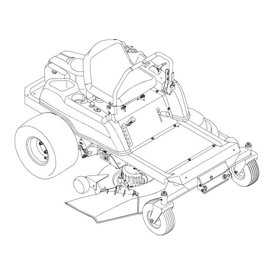
Tractor w/42" mower deck
Hide thumbs
Also See for RZT 42:
- Operator's manual (84 pages) ,
- Specifications (2 pages) ,
- Operator's manual (80 pages)
Advertisement
Quick Links
Download this manual
See also:
Operator's Manual
®
OPERATOR'S
MANUAL
IES
TRACTOR
Model Number
RZT 42
w/42" Mower Deck
IMPORTANT:
READ SAFETY
RULES AND INSTRUCTIONS
CAREFULLY
Warning:
This unit is equipped with an internal combustion engine and should not be used on or near any unimproved
forest-
covered, brush-covered
or grass-covered
land unless the engine's exhaust system is equipped with a spark arrester meeting
applicable local or state laws (if any),
If a spark arrester is used, it should be maintained in effective working order by the operator,
In the State of California the above is required by law (Section 4442 of the California
Public Resources Code), Other states may have
similar laws, Federal laws apply on federal lands, A spark arrester for the muffler is available through your nearest engine authorized
service dealer or contact the service department,
P.O. Box 361131 Cleveland, Ohio 44136-0019.
CUB CADET
LLC
P.O. BOX 361131
CLEVELAND,
OHIO 44136-0019
[www.cubcadet.com]
PRINTED IN U.S.A.
FORM NO. 769-02748A
(04/07)
Advertisement

Related Manuals for Cub Cadet RZT 42


Summary of Contents for Cub Cadet RZT 42
- Page 1 Federal laws apply on federal lands, A spark arrester for the muffler is available through your nearest engine authorized service dealer or contact the service department, P.O. Box 361131 Cleveland, Ohio 44136-0019. CUB CADET P.O. BOX 361131 CLEVELAND, OHIO 44136-0019 [www.cubcadet.com]...
- Page 2 TABLE OF CONTENTS TRACTOR PREPARATION ....................IMPORTANT SAFE OPERATION PRACTICES ..............SAFETY DECALS AND LABELS ................... SLOPE GAUGE ........................TO THE OWNER ........................CALLING SERVICE INFORMATION ..................RECORDING MODEL AND SERIAL NUMBER INFORMATION ........... SECTION 1: CONTROLS AND FEATURES ................. SECTION 2: OPERATION ....................
- Page 3 POSITION DRIVE CONTROL LEVERS CONNECT THE BATTERY The drive control levers of the tractor are lowered for shipping purposes. To accomplish this, the flange lock related accessories contain lead and lead WARNING: Battery posts, terminals nut, hex screw, and flat washer normally used to secure compounds.
- Page 4 WARNING • The engine exhaust, some of its constituents, and certain vehicle components contain or emit chemicals known to the State of California to cause cancer, birth defects or other reproductive harm. • This unit is equipped with an internal combustion engine and should not be used on or near any unimproved forest-covered, brush-covered, or grass-covered...
- Page 5 III. CHILDREN Useonlyaccessories a pproved forthis machine Tragic accidents can occur if the operator is not alert Cub Cadet. Read, understand and follow all to the presence of children. Children...
- Page 6 5. Never allow children under 14 years old to After striking a foreign object, stop the engine, operate the machine. Children 14yearsandover remove wire from spark plug shouldonly operatethe machineunderclose thoroughly inspect the mower for any damage. parental s upervision a ndproperinstruction. Repair damage before...
- Page 7 SAFETY DECALS AND LABELS Keep product safety graphics (decals) clean• Replace any safety graphic that is damaged, destroyed, missing, paint- ed over or can no longer be read. Replacement safety graphics are available through your dealer• GENERAL OPERATINGINSTRUCTIONS GENERAL SAFETY INSTRUCTIONS -LOCATED ON RIGHT CONSOLE - LOCATED ON LEFT CONSOLE...
- Page 8 USE THIS PAGE AS A GUIDE TO DETERMINE SLOPES WHERE YOU MAY NOT OPERATE SAFELY. SIGHT AND HOLD THIS LEVEL WITH A VERTICAL TREE I_ I A POWER POLE i .91 A CORNER OF A BUILDING .."9 OR A FENCE POST "...
- Page 9 LEVEL SURFACE before pulling the transmission bypass rods to the engaged position (transmission disengaged). Your local authorized Cub Cadet dealer is interested in the performance you receive from your tractor, and with the maintenance needed to ensure the satisfactory operation of your tractor. The dealer has trained service personnel familiar with the latest servicing information, is equipped with the latest tools, and has a complete line of genuine Cub Cadet service parts which assure proper fit and high quality.
- Page 10 SECTION 1" CONTROLS AND FEATURES Figure 6 A. Deck Height Index H. Storage Tray B. Deck Lift Handle J. Seat Adjustment Lever (Not Seen) C. RH and LH Drive Control Levers K. Fuel Tank Cap L. Hour Meter/Indicator Panel D. Ignition Switch E.
- Page 11 NOTE: References to LEFT, RIGHT, FRONT, and Power Take-Off (PTO) Switch REAR indicate that position on the tractor when The PTO switch is located on the RH console to the facing forward while seated in the operator's seat. right of the operator's seat. Deck Height Index The deck height index consists of six index notches located on the front/right of the seat box frame.
- Page 12 Panel engine while this indicator is illuminated. Contact The hour meter/indicator panel is located on the LH your Cub Cadet dealer to have the tractor and console to the left of the operator's seat. engine inspected. NOTE: The oil pressure...
- Page 13 Pull the throttle control handle rearwardto • Pull the lever fully upward and to the left; then decrease t heengine speed. lower into the "J" slot to engage the parking brake. When starting the engine, push the control handlefully forwardintothe "CHOKE" p osition. •...
- Page 14 If the interlock Engaged system should ever malfunction, do not operate the tractor. Contact your authorized Cub Cadet Dealer. • The safety interlock system prevents the engine from cranking or starting unless the RH and LH ..J...
- Page 15 COLDWEATHER STARTING • Place the throttle control lever between half and full throttle. • Whenstarting theengine attemperatures nearor belowfreezing, ensure thecorrect v iscosity motor • Turn the ignition key to the "OFF" position and oil is usedin the engineandthe batteryis fully remove the key from the ignition switch.
- Page 16 • Movethe RHandLHdrivecontrolleversinward intheneutral p osition. S eeFigure12. DRIVING FORWARD Faster Control Lever Moved Inward and in Neutral Slower Neutral Position Figure 13 Figure 12 • To slow the tractor move the controls lever NOTE: If the control levers are not even in the neutral rearward to attain the desired speed, or move the position, refer to Section 3 and adjust the levers so levers to the neutral position to stop the tractor.
- Page 17 Toturntothe right,movetherightdrivecontrol IMPORTANT: Always maintain your grasp on the leverrearward o fthe leftlever. S eeFigure 15. drive control levers. Do not release the levers to slow the tractor or to return to neutral. FORWARD RIGHT T URN Turning While Driving Rearward •...
- Page 18 STOPPING THE TRACTOR Executing a Zero Turn • Move both drive control levers to the neutral tractor MUST STOPPED. position to stop the motion of the tractor. WARNING: When executing a zero turn, Executing a zero turn while the tractor is •...
- Page 19 • Mow across slopes, not up and down. If mowing not working as designed, contact you Cub Cadet a slope, start at bottom and work upward dealer to have the tractor inspected. DO NOT operate ensure turns are made uphill.
- Page 20 SECTION 3: ADJUSTMENTS ADJUSTING THE OPERATORS SEAT • Reposition the control lever to align with the other set of holes in the pivot bracket and insert the To adjust the position of the seat, move and hold the shoulder screw removed earlier. Fasten with the seat adjustment lever toward the left.
- Page 21 SECTION 4: MAINTENANCE Perform all maintenance procedures at the intervals given in the instructions. RECOMMENDED SAE VISCOSITY GRADES 40°C -30°C -20°C -10°C 0°C 10°C 20°C 30°C ENGINE MAINTENANCE Engine maintenance procedures must be performed at the intervals given in the following instructions. Checking Engine Oil Level Check engine oil level before each use as follows:...
- Page 22 • Applya thincoator newoil onthe rubber gasket Remove the air cleaner element with the integral ofthenewoilfilter. rubber seal. See Figure 25. • Install t he newoilfilteronthefilteradapter. H and tighten untilthefiltergasket c ontacts the adapter, Air Cleaner thentighten thefilteranadditional 3/4-1turn. Element •...
- Page 23 Remove plug check its condition. should be performed by your Cub Cadet dealer. Replace the plug if worn or reuse is questionable. NOTE: Do not clean the spark plug in a machine GENERAL BATTERY INFORMATION using abrasive grit. Some grit could remain in the...
- Page 24 MAXIMUM rate of 10 amps. system. If a function of the safety interlock system described earlier is not functioning properly, have the Voltmeter State of Charging electrical system checked by your Cub Cadet dealer. Reading Charge Time 12.7 100% Full Charge 12.4...
- Page 25 Wheel rotation should stop. Pull one rod toward the front of the tractor until If it does not, contact your Cub Cadet dealer. the flange on the rod is forward of the keyhole slot in the frame assembly.
- Page 26 • If the rotation stops,adjust t heferruleupor down • Tighten the jam nut against the console and repo- thecontrol r odas necessary to alignwiththe hole sition the control lever if necessary. in the transmission controlarm. Re-insert t he TRANSMISSION DRIVE BELT ferruleintothe holeinthecontrol a rmandsecure withtheinternal cotterpin.
- Page 27 TRACTOR STORAGE Emptying the fuel system: If your tractoris not goingto be operatedfor an • Prior to putting the tractor in storage, monitor extended periodof time(thirtydaysto approximately fuel consumption with the goal of running the six months), the tractorshouldbe prepared for stor- fuel tank empty.
- Page 28 SECTION 5: MOWER DECK This section contains removal, installation, adjust- Rolling the belt off the PTO pulley. ment, and maintenance information for the 42-inch • Using the deck lift handle, raise the deck to the mower deck. upper position that allows for the most horizontal run of the belt between the deck idler pulleys and DECK REMOVAL the PTO pulley on the bottom of the engine.
- Page 29 7. Slide the deck forwardso that the deck front Route the backside of the belt around the fixed hanger r odcanbe liftedoutofthetwoslotsofthe idler pulley of the deck. Refer to Figure 34. frontdeckbracket. A fter liftingthe front hanger Working from the middle of the tractor, pivot the rod out of the slots,slidethe deckrearward so idler bracket/movable pulley rearward against the...
- Page 30 LEVELING THEMOWER DECK Withthe deckraised off of the ground, r otatethe bladessothattheyareparallel totheframeofthe Whenleveledcorrectlythe mowerdeckshouldbe tractor. levelsideto side,andshouldbe approximately a 1/8 to 1/4inchlowerinthefrontofthedeck. If the sideto side levelingwas donecorrectly, measuringjust the right blade should be Sideto SideLeveling acceptable t o attainthecorrect b acktofrontpitch If the cuttingdeckappears to bemowing unevenly, a ofthedeck.
- Page 31 ADJUSTING THE GAUGE WHEELS • Attach the nozzle adapter to a standard garden hose connected to a water supply. The cutting height of the mower deck can be set in any of six height settings using the deck lift handle of •...
- Page 32 Theblades mayberemoved a sfollows. upward toward the top of the deck. Tighten the blade nuts to 70-90 ft. Ibs. • Remove the deckfrombeneath the tractor, ( refer to DeckRemoval o npage28)thengently flipthe Reinstall the deck (refer to Deck Installation deckovertoexpose itsunderside. page 29).
- Page 34 KOHLER FEDERAL AND CALIFORNIA EMISSION CONTROL SYSTEMS LIMITED WARRANTY SMALL OFF-ROAD EQUIPMENT ENGINES The U.S. Environmental Protection Agency (EPA), the California Air Resources Board (CARB), and Kohler Co. are pleased to explain the Federal and California Emission Control Systems Warranty on your small off-road equipment engine.
- Page 35 CALIFORNIA EMISSION CONTROL WARRANTY STAT EMENT YOUR W ARRANTY RIGHTS AND OBLIGATIONS The California Air ResourcesBoard and MTD Consumer Group Inc. are pleasedto explain the evaporative emission control system warranty on your 2007 lawn mower. In California, new lawn mower must be designed, built and equipped to meet the State's stringent anti-smog standards. MTD Consumer Group Inc. must warrant the EECSon your lawn mower for the period of time listed below provided there has been no abuse, neglect or improper maintenance of your lawn mower.
- Page 36 Without limiting the foregoing, this limited warranty does not provide The limited warranty set forth below is given by Cub Cadet LLC with coverage in the following cases: respect to new merchandise purchased or leased and used in the a.
- Page 37 Federal laws apply on federal lands, A spark arrester for the muffler is available through your nearest engine authorized service dealer or contact the service department, P.O. Box 361131 Cleveland, Ohio 44136-0019. CUB CADET P.O. BOX 361131 CLEVELAND, OHIO 44136-0019 [www.cubcadet.com]...
- Page 38 TABLE OF CONTENTS TRACTOR PREPARATION ....................IMPORTANT SAFE OPERATION PRACTICES ..............SAFETY DECALS AND LABELS ................... SLOPE GAUGE ........................TO THE OWNER ........................CALLING SERVICE INFORMATION ..................RECORDING MODEL AND SERIAL NUMBER INFORMATION ........... SECTION 1: CONTROLS AND FEATURES ................. SECTION 2: OPERATION ....................
- Page 39 POSITION DRIVE CONTROL LEVERS CONNECT THE BATTERY The drive control levers of the tractor are lowered for shipping purposes. To accomplish this, the flange lock related accessories contain lead and lead WARNING: Battery posts, terminals nut, hex screw, and flat washer normally used to secure compounds.
- Page 40 WARNING • The engine exhaust, some of its constituents, and certain vehicle components contain or emit chemicals known to the State of California to cause cancer, birth defects or other reproductive harm. • This unit is equipped with an internal combustion engine and should not be used on or near any unimproved forest-covered, brush-covered, or grass-covered...
- Page 41 III. CHILDREN Useonlyaccessories a pproved forthis machine Tragic accidents can occur if the operator is not alert Cub Cadet. Read, understand and follow all to the presence of children. Children...
- Page 42 5. Never allow children under 14 years old to After striking a foreign object, stop the engine, operate the machine. Children 14yearsandover remove wire from spark plug shouldonly operatethe machineunderclose thoroughly inspect the mower for any damage. parental s upervision a ndproperinstruction. Repair damage before...
- Page 43 SAFETY DECALS AND LABELS Keep product safety graphics (decals) clean• Replace any safety graphic that is damaged, destroyed, missing, paint- ed over or can no longer be read. Replacement safety graphics are available through your dealer• GENERAL OPERATINGINSTRUCTIONS GENERAL SAFETY INSTRUCTIONS -LOCATED ON RIGHT CONSOLE - LOCATED ON LEFT CONSOLE...
- Page 44 USE THIS PAGE AS A GUIDE TO DETERMINE SLOPES WHERE YOU MAY NOT OPERATE SAFELY. SIGHT AND HOLD THIS LEVEL WITH A VERTICAL TREE I_ I A POWER POLE i .91 A CORNER OF A BUILDING .."9 OR A FENCE POST "...
- Page 45 LEVEL SURFACE before pulling the transmission bypass rods to the engaged position (transmission disengaged). Your local authorized Cub Cadet dealer is interested in the performance you receive from your tractor, and with the maintenance needed to ensure the satisfactory operation of your tractor. The dealer has trained service personnel familiar with the latest servicing information, is equipped with the latest tools, and has a complete line of genuine Cub Cadet service parts which assure proper fit and high quality.
- Page 46 SECTION 1" CONTROLS AND FEATURES Figure 6 A. Deck Height Index H. Storage Tray B. Deck Lift Handle J. Seat Adjustment Lever (Not Seen) C. RH and LH Drive Control Levers K. Fuel Tank Cap L. Hour Meter/Indicator Panel D. Ignition Switch E.
- Page 47 NOTE: References to LEFT, RIGHT, FRONT, and Power Take-Off (PTO) Switch REAR indicate that position on the tractor when The PTO switch is located on the RH console to the facing forward while seated in the operator's seat. right of the operator's seat. Deck Height Index The deck height index consists of six index notches located on the front/right of the seat box frame.
- Page 48 Panel engine while this indicator is illuminated. Contact The hour meter/indicator panel is located on the LH your Cub Cadet dealer to have the tractor and console to the left of the operator's seat. engine inspected. NOTE: The oil pressure...
- Page 49 Pull the throttle control handle rearwardto • Pull the lever fully upward and to the left; then decrease t heengine speed. lower into the "J" slot to engage the parking brake. When starting the engine, push the control handlefully forwardintothe "CHOKE" p osition. •...
- Page 50 If the interlock Engaged system should ever malfunction, do not operate the tractor. Contact your authorized Cub Cadet Dealer. • The safety interlock system prevents the engine from cranking or starting unless the RH and LH ..J...
- Page 51 COLDWEATHER STARTING • Place the throttle control lever between half and full throttle. • Whenstarting theengine attemperatures nearor belowfreezing, ensure thecorrect v iscosity motor • Turn the ignition key to the "OFF" position and oil is usedin the engineandthe batteryis fully remove the key from the ignition switch.
- Page 52 • Movethe RHandLHdrivecontrolleversinward intheneutral p osition. S eeFigure12. DRIVING FORWARD Faster Control Lever Moved Inward and in Neutral Slower Neutral Position Figure 13 Figure 12 • To slow the tractor move the controls lever NOTE: If the control levers are not even in the neutral rearward to attain the desired speed, or move the position, refer to Section 3 and adjust the levers so levers to the neutral position to stop the tractor.
- Page 53 Toturntothe right,movetherightdrivecontrol IMPORTANT: Always maintain your grasp on the leverrearward o fthe leftlever. S eeFigure 15. drive control levers. Do not release the levers to slow the tractor or to return to neutral. FORWARD RIGHT T URN Turning While Driving Rearward •...
- Page 54 STOPPING THE TRACTOR Executing a Zero Turn • Move both drive control levers to the neutral tractor MUST STOPPED. position to stop the motion of the tractor. WARNING: When executing a zero turn, Executing a zero turn while the tractor is •...
- Page 55 • Mow across slopes, not up and down. If mowing not working as designed, contact you Cub Cadet a slope, start at bottom and work upward dealer to have the tractor inspected. DO NOT operate ensure turns are made uphill.
- Page 56 SECTION 3: ADJUSTMENTS ADJUSTING THE OPERATORS SEAT • Reposition the control lever to align with the other set of holes in the pivot bracket and insert the To adjust the position of the seat, move and hold the shoulder screw removed earlier. Fasten with the seat adjustment lever toward the left.
- Page 57 SECTION 4: MAINTENANCE Perform all maintenance procedures at the intervals given in the instructions. RECOMMENDED SAE VISCOSITY GRADES 40°C -30°C -20°C -10°C 0°C 10°C 20°C 30°C ENGINE MAINTENANCE Engine maintenance procedures must be performed at the intervals given in the following instructions. Checking Engine Oil Level Check engine oil level before each use as follows:...
- Page 58 • Applya thincoator newoil onthe rubber gasket Remove the air cleaner element with the integral ofthenewoilfilter. rubber seal. See Figure 25. • Install t he newoilfilteronthefilteradapter. H and tighten untilthefiltergasket c ontacts the adapter, Air Cleaner thentighten thefilteranadditional 3/4-1turn. Element •...
- Page 59 Remove plug check its condition. should be performed by your Cub Cadet dealer. Replace the plug if worn or reuse is questionable. NOTE: Do not clean the spark plug in a machine GENERAL BATTERY INFORMATION using abrasive grit. Some grit could remain in the...
- Page 60 MAXIMUM rate of 10 amps. system. If a function of the safety interlock system described earlier is not functioning properly, have the Voltmeter State of Charging electrical system checked by your Cub Cadet dealer. Reading Charge Time 12.7 100% Full Charge 12.4...
- Page 61 Wheel rotation should stop. Pull one rod toward the front of the tractor until If it does not, contact your Cub Cadet dealer. the flange on the rod is forward of the keyhole slot in the frame assembly.
- Page 62 • If the rotation stops,adjust t heferruleupor down • Tighten the jam nut against the console and repo- thecontrol r odas necessary to alignwiththe hole sition the control lever if necessary. in the transmission controlarm. Re-insert t he TRANSMISSION DRIVE BELT ferruleintothe holeinthecontrol a rmandsecure withtheinternal cotterpin.
- Page 63 TRACTOR STORAGE Emptying the fuel system: If your tractoris not goingto be operatedfor an • Prior to putting the tractor in storage, monitor extended periodof time(thirtydaysto approximately fuel consumption with the goal of running the six months), the tractorshouldbe prepared for stor- fuel tank empty.
- Page 64 SECTION 5: MOWER DECK This section contains removal, installation, adjust- Rolling the belt off the PTO pulley. ment, and maintenance information for the 42-inch • Using the deck lift handle, raise the deck to the mower deck. upper position that allows for the most horizontal run of the belt between the deck idler pulleys and DECK REMOVAL the PTO pulley on the bottom of the engine.
- Page 65 7. Slide the deck forwardso that the deck front Route the backside of the belt around the fixed hanger r odcanbe liftedoutofthetwoslotsofthe idler pulley of the deck. Refer to Figure 34. frontdeckbracket. A fter liftingthe front hanger Working from the middle of the tractor, pivot the rod out of the slots,slidethe deckrearward so idler bracket/movable pulley rearward against the...
- Page 66 LEVELING THEMOWER DECK Withthe deckraised off of the ground, r otatethe bladessothattheyareparallel totheframeofthe Whenleveledcorrectlythe mowerdeckshouldbe tractor. levelsideto side,andshouldbe approximately a 1/8 to 1/4inchlowerinthefrontofthedeck. If the sideto side levelingwas donecorrectly, measuringjust the right blade should be Sideto SideLeveling acceptable t o attainthecorrect b acktofrontpitch If the cuttingdeckappears to bemowing unevenly, a ofthedeck.
- Page 67 ADJUSTING THE GAUGE WHEELS • Attach the nozzle adapter to a standard garden hose connected to a water supply. The cutting height of the mower deck can be set in any of six height settings using the deck lift handle of •...
- Page 68 Theblades mayberemoved a sfollows. upward toward the top of the deck. Tighten the blade nuts to 70-90 ft. Ibs. • Remove the deckfrombeneath the tractor, ( refer to DeckRemoval o npage28)thengently flipthe Reinstall the deck (refer to Deck Installation deckovertoexpose itsunderside. page 29).
- Page 70 KOHLER FEDERAL AND CALIFORNIA EMISSION CONTROL SYSTEMS LIMITED WARRANTY SMALL OFF-ROAD EQUIPMENT ENGINES The U.S. Environmental Protection Agency (EPA), the California Air Resources Board (CARB), and Kohler Co. are pleased to explain the Federal and California Emission Control Systems Warranty on your small off-road equipment engine.
- Page 71 CALIFORNIA EMISSION CONTROL WARRANTY STAT EMENT YOUR W ARRANTY RIGHTS AND OBLIGATIONS The California Air ResourcesBoard and MTD Consumer Group Inc. are pleasedto explain the evaporative emission control system warranty on your 2007 lawn mower. In California, new lawn mower must be designed, built and equipped to meet the State's stringent anti-smog standards. MTD Consumer Group Inc. must warrant the EECSon your lawn mower for the period of time listed below provided there has been no abuse, neglect or improper maintenance of your lawn mower.
- Page 72 Without limiting the foregoing, this limited warranty does not provide The limited warranty set forth below is given by Cub Cadet LLC with coverage in the following cases: respect to new merchandise purchased or leased and used in the a.