Table of Contents
Advertisement
Caution:
Read and foEiow
all Safety
Rules
and Ilnstructaons
Before
Operating
This Equipment
!
/
/
/
,,,,,,
,,
"IM"'I
' "r '"
I
I
I I'11"IIl,l,llll
I'=11
'11
I
--
®
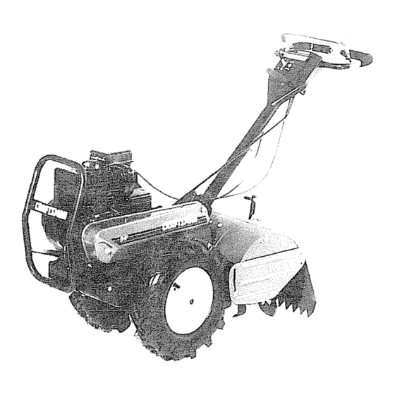
5=0 HP
!7 INCH TnNE WBDTH
REAR TJNE TILLER WUTH
COUNTER ROTAT!
TI
Assembly
Operation
• Customer ResponsibHUties
o Service and Adjustment
• Repair Parts
ii i.rll
. ....-.
i..i
. i.i,
i
i
..... _lllll.,.i.
.i..i
.iii rllr
. II'"MI"I"II'
IIIII
Sears, Roebuck and Co., Chicago, DL60684 U.S.A.
.
i
Advertisement
Table of Contents

Related Manuals for Craftsman 917.299850


Summary of Contents for Craftsman 917.299850
- Page 1 ,,,,,, "IM"'I ' "r '" I I'11"IIl,l,llll I'=11 ® 5=0 HP Caution: !7 INCH TnNE WBDTH Read and foEiow all Safety Rules REAR TJNE TILLER WUTH and Ilnstructaons COUNTER ROTAT! Before Operating This Equipment Assembly Operation • Customer ResponsibHUties o Service and Adjustment •...
- Page 2 SAFETY RULES Safe Operation Practices for Walk.Behind Powered Rotary Tillers TRAINING If the unit should start to vibrate abnormally, stop the engine (motor) and check immediately for the cause. • Read the Owner's Manual carefully. Be thoroughly Vibration is generally a warning of trouble. Tamiliar with the controls and the proper use of the Stop the engine (motor) when leaving the operating equipment...
- Page 3 Repairs necessary because of operator abuse or negligence, including bent crankshafts and the failure to maintain the equipment according to the instructions contained in the owner's manual ° If this Craftsman Tiller is used for commercial or rental purposes, this Warranty applies for only 30 days from the date of purchase° WARRANTY...
-
Page 4: Table Of Contents
MAINTENANCE SCHEDULE ........SAFETY RULES ............CUSTOMER RESPONSIBILITIES ...... 3,13-15 SERVICE & ADJUSTMENTS ......... 15-18 PRODUCT SPECIFICATIONS ........STORAGE ..............WARRANTY ..............TROUBLESHOOTING ..........ACCESSORIES ............. REPAIR PARTS-TILLER ........21-26 ASSEMBLY ..............REPAIR PARTS-ENGINE ........27-31 OPERATION ............. 9-12 INDEX Engine (cont'd) Accessories .......... - Page 5 ......I¸l ......, i, i, These accessories were available when the tiller was purchased. They are also available at most Sears Retail outlets, Catalog and Service Centers. Most Sears Stores can order repair parts for you when you provide the model number of your tiller.
- Page 6 iiiii IIIIHI OPERATOR'S POSiTiON (See Fig. 1) TO ASSEM BLE YOUR TILLER YOU WILL NEED: (1) Utility knife The righthand (R.H.) and left hand (LH,) sides of your tiller (1) Wire cutter are determined from the operator's position while standing behind tiller.
- Page 7 i, ,,i,, ,, UNPACKING CARTON (See Fig. 2) • Grasp handle assembly. Hold in"up" position. Be sure handle lock remains in gearcase notch Slide handle iiii ..... 1,,,11 ,i ,,11 assembly into position. staples when handling or disposing of CAUTION: Be careful of exposed cartoning material,...
- Page 8 i,,,i,,,i i ,i,, i I,H,, iii, H " ' ' i ..i,,i,,i,,,,, ..i'1 ,HII REMOVE TILLER FROM CRATE CONNECT SHIFT ROD (See Fig. 6) ° Make sure shift lever indicator is in "N" (neutral) posi- Insert end of shift rod farthest from bend into hole of tion (See Fig.,6) shift lever indicator°...
- Page 9 ....... i, i MI 11111 I I ,I,l, ll OPERATION iiii i,iii i ,, ii ii1,1 i ,, ii KNOW YOUR TILLER READ THIS OWNER'S MANUAL AND SAFETY RULES BEFORE OPERATING YOUR TILLER, Compare the illustrations with your tiller to familiarize yourself with the location of various controls and adjustments. Save this manual for future reference_ DRWE THROTTLE...
- Page 10 The operation of any tiller can result in foreign objects thrown into the eyes, which can result in severe eye damage. Always wear safety glasses or eye shields before starting your tiller and while tilling. We recommend wide vision safety mask for over the spectacles or standard safety glasses.
-
Page 11: Customer Responsibilities 3
OPEF ATBON ..=......... TURNING The engine in your unit has been shipped, from the factory, already filled with SAE 30 summer weight oil. Release the drive control bar° • With engine level, clean area around oil filler plug and Move throttle control to "SLOW"... - Page 12 ....ii1,11 i i1,,i ... i..OPl=FIATmO iMII,II ,1111,i ,,i i ,11,1,1,1,1,11 i, ,, ii I Soil conditions are important for proper tilling., Tines will TO START ENGINE (See Fig. 13) not readily penetrate dry, hard soil which may contrib- ute to excessive bounce and difficult handling of your CAUTION: Keep the tine control in...
-
Page 13: Air Cleaner
..i IlUNU,i ... I ,N-II I'111 CUSTOME RESPONSIBILUTmES iiii1,1 ,i,i ,i,,,i,i SCHEDULE FILL IN DATES /__// AS YOU COMPLETE SERVICE DATES REGULAR SERVICE Check Engine Oil Level -::- , ii illU, Change Engine Oil t_1,2 Oil Pivot Points ii i ,,i,, ii,lJ, UJl_ Inspect Spark Arrester Muffler... - Page 14 ....====,=,=1 ..= IHI-I. ==,.H ¸ CUSTOME RESPONSMBILITIE$ Disconnect spark plug wire before performing any maintenance (except carburetor adjustment) to Prevent firest Keep the engine free of grass, leaves, spilled oil, or fuel. Remove fuel from tank before prevent accidental starting of engine. tipping unit for maintenance.
- Page 15 BmLUTIES TRANSMISSION MUFFLER Your transmission is sealed and will only require lubrication Do not operate tiller without muffler° Do not tamper with if serviced, exhaust system. Damaged mufflers or spark arresters could create a fire hazard. Inspect periodically and replace CLEANING if necessary,, If your engine is equipped with a spark...
-
Page 16: Belt Guard
TO REMOVE BELT GUARD (See Fig. 22) TO REPLACE GROUND DRIVE BELT (See Figs. 22 and 23) • Remove Loll. outer' side shield by removing nuts "A" and "B" (See Fig, 11)_ Remove L,H. outer side shield, move left wheel, and remove belt guard as described in'q'O REMOVE BELT •... - Page 17 ill ,ill SERVICE AN ADJUSTMENTS To maintain the superb tilling performance of this TINE REPLACEMENT (See Figs. 24, 25 and machine the tines should be checked for sharpness, wear, and bending, particularly the tines which are next i"A....to the transmission, if the gap between the tines CAUTION: Tines are sharp.
- Page 18 SERVICE AN FINAL SETTING ENGINE Start engine and allow to warm for five minutes. Make TO ADJUST THROTTLE CONTROL CABLE final adjustments with engine running at idle and drive control bar in "DISENGAGED" position. (See Fig. 27) • With throttle control lever in "SLOW" position, turn idle •...
- Page 19 STORAGE iiiii i iiiii ENGINE Immediately prepare your tiller for storage at the end of the season or if the unit will not be used for 30 days or more. Drain oil (with engine warm) and replace with clean oil. (See "ENGINE"...
- Page 20 PROBLEM CAUSE CORRECTION iiiii ..... Wilt not start Out of fuel Fill fuel lank Engine net "CHOKED" properly. See "TO START ENGINE" in Operation section. Engine flooded. Wait several minutes before attempting to start. Dirty air cleaner. Replace air cleaner cartridge. Water in fuel.
- Page 21 REPAUR PARTS 5 HP 17" TriLLER = - MODEL NUMBER 917.299850 HANDLES PART DESCRIPTION PART DESCRIPTION 121213X Handle, Assemble 110707X Cap, Sleeve 110674X 121145X Clip, Plastic, Cable Grip, Handle 110673X Grommet, Handle 86777 Screw, Hex, Washer Hd, Slotted #10-24 x 1/2 127254X Bar, Drive Control Assembly 6712J...
-
Page 22: Repair Parts
REPAIR PARTS 5 HP 17" TILLER - - MODEL NUMBER 917.299850 MAINFRAME, LEFT SiDE PART DESCRIPTION 73970500 * Locknut, Hex, Flange 5/16-18 STD551137 * Washer, Lock 3/8 STD541037 * Nut, Hex 3/8-16 74930568 Bolt, He)( 5/16-18 x 4-1/4 STD571810 * Pin, Roll 110111X Lever, Shift STD532505... - Page 23 REPAnR PARTS 5 HP 17" TILLER - - MODEL NUMBER 917.299850 MAINFRAME, RIGHT SIDE PART DESCRIPTION PART DESCRIPTION 12455tX 5015J Tire Bumper 73970500 128952 Locknut, Hex, Flange 5/16-18 STD551031 * Washer 11/32 x 11/16 x t6 Ga. 795R Tire Valve 74760512 Bolt, Hex 5/16-18 x 3/4 STD54t431...
- Page 24 17" TILLER - - MODEL NUMBER 917.299850 PART DESCRIPTION ..> 102128)( O-Ring 102100X Bearing, Shaft, Ground Drive 106390X Spacer 0.765 x 1.125 x 1 ..23 102134X Chain #35-50 Pitch 124458X Ground Shaft Assembly PART DESCRIPTION 102106X Bearing, Shaft, GroundDrive I06388X Spacer 0°70 x 1.00 x 1.150 132724 Transmission...
- Page 25 REPAIR PARTS 5 HP 17" TILLER - - MODEL NUMBER 917.299850 TINE SHIELD PART DESCRIPTION PART DESCRIPTION 98000129 Nut, Flange 5/I6-I8 102701X Grip 104086X459 Shield, Side, Outer L, H. STD54t037 *Nut, Hex 3/8-16 8393J Pin, Stake, Depth 102156X Stake, Depth 12000036 Ring, Klip 74930632...
- Page 26 REPAnR PARTS 17" TILLER - - MODEL NUMBER 917.299850 TINE ASSEMBLY PART DESCRIPTION PART DESCRIPTION 4459J Tine, Outer, L.H. 74610616 Bolt, Hex 3/8-24 x t 132673 Clevis Pin 4460J Tine, Outer, R.Ho 6554J Tine, Inner, L,H, 132728 Assembly, Hub and Plate, R_H, STD624008 6555J * Clip, Hairpin...
- Page 27 REPARR PARTS 5 HP 17" TILLER - - MODEL NUMBER 917.299850 ENGINE, BRIGGS & STRATTON - - MODEL NUMBER 130202, TYPE NO. 3273-01 _:_ 614 *SPECIAL TOOLS REQUIRED TO INSTALL [358 GASKET SET I {1019 LABEL KIT I...
- Page 28 REPAnR PARTS 5 HP 17" TILLER - - MODEL NUMBER 917.299850 ENGINE, BRiGGS & STRATTON - .. MODEL NUMBER 130202, TYPE NO. 3273-01 127A 202A...
- Page 29 REPAIR PARTS 5 HP 17" TILLER - = MODEL NUMBER 917.299850 ENGINE, BRIGGS & STRATTON - - MODEL NUMBER 130202, TYPE NO. 3273-01...
-
Page 30: Throttle
REPAIR PARTS NUMBER 917.299850 5 HP 17" TILLER - .- MODEL NUMBER 130202, TYPE NO. 3273-01 ENGINE, BRIGGS & STRATTON - - MODEL KEY PART KEY PART NO. NO. DESCRIPTION NO. NO, DESCRIPTION 395990 Cylinder Assembly 221876 Lock, Connecting Rod Screw 297565 Bushing, Cylinder (Special Tools 92296... -
Page 31: Muffler
REPAIR PARTS 5 HP 17" TILLER = = MODEL NUMBER 917.299850 ENGINE, BRIGGS & STRA3"FON = - MODEL NUMBER 130202, TYPE NO. 3273-01 KEY PART KEY PART NO. NO. DESCRIPTION NO, NO, DESCRIPTION 152 260575 Spring, Throttle Adjustment 210959 Cover, Diaphragm 490589 Screw Assembly 93141... -
Page 32: Transmission
® 5=0 HP OWNER'S 17 iNCH TI WUDTH MANUAL REAR TJNE TILLER WiTH COUNTE ROTATING TINES MODEL NO. Each tiller has its own model number. Each engine has its own model 917.2998,50 number, The model number for your tiller wilt be found on a plate attached to the top of the transmission.