Table of Contents
Advertisement
Quick Links
OWNER'S
MANUAL
MODEL NO.
917.255572
Caution:
Read and follow
all Safety Rules
and Instructions
Before Operating
This Equipment
i ,i,,,,ii,
iiii,iii,,,,,iiiiii
®
oAssembHy
° Operation
oCustomer AesponsibiHties
o Service and Adjustment
oRepair Parts
Sears, Roebuck and Co., Chicago,
IL 60684 U.S.A.
H n = =m,=
NHnH=HHHnnH=
,
I,
i= =JH
Advertisement
Table of Contents

Related Manuals for Craftsman 917.255572


Summary of Contents for Craftsman 917.255572
- Page 1 OWNER'S MANUAL MODEL NO. 917.255572 i ,i,,,,ii, iiii,iii,,,,,iiiiii ® Caution: Read and follow all Safety Rules and Instructions Before Operating This Equipment oAssembHy ° Operation oCustomer AesponsibiHties o Service and Adjustment oRepair Parts Sears, Roebuck and Co., Chicago, IL 60684 U.S.A. H n = =m,= NHnH=HHHnnH= i= =JH...
- Page 2 SAFETY RULES Safe Operation Practices for Ride.On Mowers IMPORTANT: THIS CUTTING MACHINE IS CAPABLE OF AMPUTATING HANDS AND FEETAND THROWING OBJECTS. FAILURE TO OBSERVETHE FOLLOWING SAFETY INSTRUCTIONS COULD RESULT IN SERIOUS INJURY OR DEATH, GENERAL OPERATION CHILDREN • Read, understand, and follow all instructions in the manual Tragic accidents can occur if the operator is not alert to the...
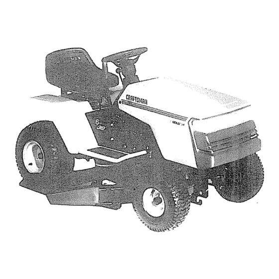
- Page 3 CONGRATULATIONS on your purchase of a Sears PRODUCT SPECIFICATIONS Tractor_ It has been designed, engineered and manu- HORSEPOWER; 12,5 factured to give you the best possible dependability performance. GASOLINE CAPACITY: 5 QUARTS Should you experience any problem you cannot easily UNLEADED REGULAR remedy, please...
-
Page 4: Table Of Contents
TABLE OF CONTENTS SAFETY RULES ............OPERATION ............11-14 PRODUCT SPECIFICATIONS ........MAINTENANCE SCHEDULE ........CUSTOMER RESPONSIBILITIES ..... 3_ 15-18 SERVICE AND ADJUSTMENTS ......19-24 WARRANTY ..............STORAGE ..............TABLE OF CONTENTS ..........TROUBLESHOOTING ..........26-27 INDEX ................REPAIR PARTS - TRACTOR ......... 28.43 TRACTOR ACCESSORIES ........... -
Page 5: Accessories
iiiitltl,_i_lt,luiitlll n,_, i ii nllnnl ACCESSORIES AND ATTACHMENTS These accessories and attachments were available when the unit was purchased. They are also available at most Sears retail outlets, catalog and service centers Most Sears stores can order these items for you when you provide the model number of your tractor. ENGINE MAINTENANCE SPARK PLUG... - Page 6 CONTENTS OF HARDWARE PACK Parts Bag contents shown full size Parts packed separately in carton Seat ÷ Metal Screws (2) Sheet #10-16 x 1/2 _ulcher Plate Steering (1) Locknut 3/8-24 Boot (I) 2-3/8" Die, Washer Battery (1) Shoulder Bolt 5/16-18 (1) Hex Bolt 1/2-13 x 1 ..•...
- Page 7 iii, i,i illlll,,ll,i illll,ii ii ,i ill,i ASSEMBLY ,,,11 I,,INHI I,I ......Illl, I ,'I,,,,U Your new tractor has been assembled at the factory with exception of those parts left unassembled for shipping purposes° To ensure safe and proper operation of your tractor, all parts and hardware you assemble must be tightened securely. Use the correct tools as necessary to insure their proper tightness, TOOLS REQUIRED FOR ASSEMBLY...
- Page 8 ==l=l ==ill i ill=l=l= ASSEMBLY HOW TO SET UP YOUR TRACTOR INSTALL SEAT (See Fig. 3) Adjust seat before tightening adjustment boll PREPARE BATTERY (See Fig. 2) • Remove cardboard packing on seat pan. CAUTION: wear eye and face shield. •...
- Page 9 'HHHH == H ¸ ' ASSE INSTALL BATTERY (See Figs. 4 & 5) CAUTION: Do not short battery termi- nals. Before Installing battery, remove metal bracelets, wristwatch bands, rings, etc. Positive terminal must be connected first to prevent sparldng from acciden- tal grounding.
- Page 10 ASSEMBLY INSTALL MULCHER PLATE TO CONVERT TO BAGGING OR DISCHARGING (See Figs. 6 & 7) Simply remove mulcher plate and store in a safe place, Your mower is now ready for discharging or installation of optional grass catcher accessory. from mower. Raise and hold guard when attaching mulcher plate and allow it to...
- Page 11 H,,, ,,,,,I,H=,I, ,, KNOW YOUR TRACTOR READ THIS OWNER'S MANUAL AND SAFE_ RULES BEFORE OPERATING YOUR TRACTOR Compare the illustrations with your tractor to familiarize yourself with the locations of various controls and adjustments. Save this manual for future reference, ATTACHMENT CLUTCH LEVER IGNITION...
- Page 12 OPEF ATIO iiiiiii HIIIIHII IIIIIIlUl The operation of any tractor can result in foreign objects thrown into the eyes, which can result in severe eye damage. Always wear safety glasses or eye shields while operating your tractor or performing any adjustments or repairs. We recommend wide vision safety mask for over the spectacles...
-
Page 13: Carburetor
TO OPERATE MOWER (See Fig. 10) If stopping is absolutely necessary, push c_utch/brake _oedal quickly to brake position and engage parking Your unit is equipped with an operator presence sensing rake. switch. Any attempt by the operator to leave the seat with Move gearshift lever to 1st gear and be sure you have the engine running and the attachment clutch engaged will... - Page 14 OPERATNON " When mowing large areas, start by turning to the right TO START ENGINE (See Fig. 9) so that clippings will discharge away from shrubs, When starting engine for the first time or if engine has fences, driveways, etc After one or two rounds, mow run out of fuel, it will take extra cranking time to move in the opposite direction making left hand turns until...
- Page 15 CUSTOME ESPONSIBIL i [,LIIU,JU, , JU,,, , ,111" I ',, ,11111,11 MAINTENANCE SCHEDULE FILL IN DATES _./i_,_ySERVtCE DATES REGULAR SERVICE ,V" ..V" ......Check Brake Operation v" Check Tire Pressure V" v" Check for Loose Fasteners ..Sharpen/Replace Mower Blades..
- Page 16 TRACTOR Always observe safety rules when performing any mainte- nance. MANDREL BLADE BRAKE OPERATION If unit requires more than six (6) feet stopping distance at high speed in highest gear, than brake must be adjusted. (See "TO ADJUST BRAKE" in Service and Adjustments section of this manual).
- Page 17 CUSTOM ESPONSI .., ,,,, HH,,U,,,,H, ,nil ENGINE BATTERY (See Fig. 15) Your unit has a battery charging system which is sufficient LUBRICATION for normal use, However, periodic charging of the battery Only use high quality detergent oii rated with API service with an automotive charger will extend it's life, classification Select the oil's SAE viscosity grade...
- Page 18 CUSTO ESPO JLmES ,11111, ii, i i.,n JUJlH,,[_,JUL[JHW AIR FILTER FOAM PRE-CLEANER (See Fig. SCREWS BLOWER HOUSING Your engine will not run properly and may be damaged by SCREWS using a dirty air filter. Clean the foam pre-€leaner element after every 25 hours of operation, more often if used in very dusty, dirty conditions.
- Page 19 SERVICE AN = = unuun == =,H, =,H, = =,,==,, =,,n CAUTION: BEFORE PERFORMING ANY SERVICE OR ADJUSTMENTS: • Depress clutch/brake pedal fully and set parking brake • Place gearshift lever In 'NEUTRAL" positlon_ • Place attachment clutch in "DISENGAGED' position.
-
Page 20: Side-To-Side 2
SERVICE AND ADJUSTMENTS III,I,,,,,,,NI I,N,II ,i ,,i i ill ,IHHI lUHHHI I TO LEVEL MOWER HOUSING FRONT-TO-BACK ADJUSTMENT (See Figs. 23 and 24) - IMPORTANT: DECK MUST BE LEVEL SIDE-TO-SIDE. Adjust the mower while tractor is parked on level ground or THE FOLLOWING FRONT-TO-BACK ADJUSTMENT driveway. - Page 21 iiii iiiii CE AN ADJUSTMENTS I,,,,,lllll,ll,IM II '_1'11 TO REPLACE MOWER BLADE DRIVE BELT WITH PARKING BRAKE =ENGAGED" (See Fig. 25) The mower blade drive belt may be replaced without tools. Park the tractor on level surface. Engage parking brake. For assistance, there is a belt installation guide decal on the mower housing.
- Page 22 SERVHCE AND ADJUSTMENTS TO ADJUST STEERING WHEEL ALIGNMENT TO START ENGINE WiTH A WEAK BATTERY (See Fig. 29) If steering wheel crossbars are not horizontal (left to right) when wheels are positioned straightforward, remove steer- ing wheel and reassemble per instructions in the Assembly CAUTION: Lead-acld batteries...
- Page 23 SERVIC5 AN ADJUSTMENTS i,,Ul TO REPLACE FUSE (See Fig. 30) TO REMOVE HOOD AND GRILL (See Fig. 31) i ,11 u N,,IHII U,I IH'HI,UU, Replace with 30 amp automotive-type ptug-in fuse. "[he fuse holder is located in the engine compartment, directiy when removing retainer springs from in front of the dash,...
-
Page 24: Throttle Control Cable 2
SERVICE AN ADJUSTMENTS ILIIIIII,,IIII,, , illllU ENGINE FI NAL S ETTt NG TO ADJUST THROTTLE CONTROL CABLE Start engine and allow to warm for five minutes. Make final adjustments with engine running and shift/motion (See Fig, 32) control lever in "NEUTRAL" position, The throttle control has been preset at the factory and adjustment should not be necessary Check adjustment as... - Page 25 Immediately prepare your tractor for storage at the end of ENGINE the season or if the unit will not be used for 30 days or more° FUEL SYSTEM IMPORTANT: IT IS IMPORTANT TO PREVENT GUM DEPOSITS FROM FORMING IN ESSENTIAL FUEL CAUTION: Never store the tractor with...
- Page 26 [LLIJUU'IU',U I I II IIII,I,T,,II TROUBLESHOOTmNG POINTS i ,i i, i i, i,i, HUHIHIIII,I PROBLEM CAU S E CO R R ECTIO N illll illllll i ill Out of fuel. Fili fuel tank Will not start Engine not"CHOKED" propedy, See "TO START ENGINE" In Operation section, Engine flooded Wait several minutes before attempting to start.
- Page 27 = H,=,,,H,H LESHOOTING POHNT$ 11 =HiHiliH , 1'1 m,.,,,=,.,=,, PROBLEM CAUSE CORRECTION Check wiring, switches and connections, if not Engine continues to run Faulty operator-safety presence control system corrected, contact Sears Service Center/Department when operator leaves seat with attachment clutch engaged Poor cut - uneven 1.
- Page 28 REPAgR PARTS 12.5 HP 38" TRACTOR - - MODEL NUMBER 917.255572 ELECTRICAL C_b. 1 4 _115...
- Page 29 132017 Harness Ign Bs Dash Headlights STD541025 * Nut Fin Rex 1/4-20 Unc 4207J Cable Ground 6¢t_a12"black 109310X Key Ign Molded Craftsman 132202 Cable Battery 6 _a 42"red 108824X 4799J Fuse 30 Amp Auto Green Cable Battery 6ga 11"red 105687X Tube Plastic 9"...
- Page 30 REPAUR PARTS "12.5 HP 38" TRACTOR - - MODEL NUMBER 917.255572 CHASSIS AND ENCLOSURES "" ,"...
- Page 31 Screw Thdrol 3/8-16xt/2 Ty-tt STD533707 * Nut Crownlock 3/8-16 Unc 74180512 Screw Mach Trhd 5/16-18uncx3/4 STD541437 STD541431 Pad Footrest Rbr Sq Craftsman *Nut Keps 5/16-18 Unc 105466X 131445)(417 Hood Asm Pnt Weld Silver Powde 134618 Bracket, Asm, Pivot, L,H,, Mower...
- Page 32 REPAIR PARTS 12.5 HP 38" TRACTOR - - MODEL NUMBER 917.255572 DRIVE 75 74 19 _ 60 (_ _)16...
- Page 33 REPARR PARTS 12.5 HP 38" TRACTOR-- MODEL NUMBER 917.255572 DRIVE PART PART DESCRIPTION DESCRIPTION 105706X Bearing Nyl 503 X 628 X 1 25 t20898X Transaxte 6sp Std Dana 110812X Washer Hardened 110422X Spring Return Brake T/a Zinc 123686× 12000039 Ring Klip #t5304-50 Pulley Transaxle Alum 127783 Pulley Idler V Groove Plastic...
- Page 34 REPAURPARTS 12.5 HP 38" TRACTOR - - MODEL NUMBER 917.255572 STEERING ASSEMBLY...
- Page 35 REPAIR PARTS 12.5 HP 38" TRACTOR - - MODEL NUMBER 917.255572 STEERING ASSEMBLY PART PART DESCRIPTION DESCRIPTION !33741 Wheel Steering Std Black 12000029 Ring Klip #t5304-75 Gear Sector 131450 Axle Asm Front 124034X Bearing Race Thrust Harden 135227 Spindle Asm Lh 6266H Screw Thdrol 3/8-16x3/4 Ty-tt 135228...
- Page 36 - - MODEL NUMBER 917.255572 SEAT ASSEMBLY PART PART DESCRIPTION DESCRIPTION 127437 Seat V350 BIk/red Craftsman 121250X Spring Cprsn 1 27 BIk Pnt 126656X Bracket Pnt Pivot Seat (blk) 123976X Nut Lock 1/4 Lge Fig Gr 5 Zinc STD523707 * Bolt Fin Hex 3/8-16unc X 3/4...
- Page 37 English 127908 Decal Eng 12 5hp lc Gold Craft 109199X Decal V-belt Dr Sch Tractor E 124489X Decal Hood Slope Rh Craftsman 108428X Decal Chassis 6 Sp 38" 124490X Decal Hood Slope Lh Craftsman 130929 Decal Mower Drive Schematic 38...
- Page 38 REPAIR PARTS 12.5 HP 38" TRACTOR - - MODEL NUMBER 917.255572 ENGINE OPTIONAL EQUIPM Spark Arrester I-,i...
- Page 39 REPAUR PARTS 12.5 HP 38" TRACTOR - - MODEL NUMBER 917.255572 ENGINE PART PART DESCRIPTION DESCRIPTION 132759 Control rhrot Rh BIk Pdl 15 10 123650X Stud 1/4 Turn (replaces 105751 17720410 Screw H ex Thd Cut 1/4-20x5/8 T 128953 Shield Pnt Heat Browning Grass 131953 Engine B&s 12.5hp t/c Dual 1 Vt STD601005...
- Page 40 REPAIR PARTS 12.5 HP 38" TRACTOR - ,. MODEL NUMBER 917.255572...
- Page 41 REPAIR PARTS 12.5 HP 38" TRACTOR - - MODEL NUMBER 917.255572 38" MOWER PART PART DESCRIPTION DESCRIPTION STD541437 * Nut, Crownlock 3/8-16 Mower Asm 38"welded 129365 131290 Belt STD54!431 * Nut, Crowntock 5/16-18 133502 Spacer, Retainer STD533107 * Bolt, Carriage 5/16-18 x 3/4 !33503 Stiffener, Arm Idler...
- Page 42 REPAaR PARTS 12.5 HP 38" TRACTOR - MODEL NUMBER 917.255572 TRANSAXLE DANA - MODEL NUMBER 4360-07 TRANSAXLE 11 '= "_" 11 _ 52 53 43"...
- Page 43 REPAIR PARTS 12.5 HP 38" TRACTOR - MODEL NUMBER 917.255572 TRANSAXLE DANA - MODEL NUMBER 4360-07 TRANSAXLE KEY PART KEY PART NO. NO. DESCRIPTION NO, NO, DESCRIPTION Gear, Bevel, 42 Teeth 3865 Housing, Upper 3853 *Washer, Plain .758 x 1.12 x o010 1919 Screw, Tapping, Large 3749...
- Page 44 REPAIR PARTS 12.5 HP 38" TRACTOR - - MODEL NUMBER 917.255572 BRIGGS & STRATTON ENGINE - MODEL NUMBER 286707, TYPE NUMBER 0437-01 .363 t4(_ ASKET *SPECIAL TOOLS REQUIRED TO INSTALL.
- Page 45 REPAIR PARTS 12.5 HP 38" TRACTOR - - MODEL NUMBER 917.255572 BRIGGS & STRATTON ENGINE - MODEL NUMBER 286707, TYPE NUMBER 0437-01 121 CARBUP_TOR OVERHAUL KIT ,_ 618...
- Page 46 REPAaR PARTS 12.5 HP 38" TRACTOR - - MODEL NUMBER 917,255572 BRIGGS & STRATTON ENGINE - MODEL NUMBER 286707, TYPE NUMBER 0437-01 __'- Housing Length NOTE: To Identlfy Brlggs and Stratton manufactured starter motors, measure the housing length. i i,iiii iiiii iiiii i J,...
-
Page 47: Installation
REPAIR PARTS 12.5 HP 38" TRACTOR - - MODEL NUMBER 917.255572 BRIGGS & STRATTON ENGINE - MODEL NUMBER 286707, TYPE NUMBER 0437-01 KEY PART KEY PART NO. NO. DESCRIPTION NO. NO. DESCRIPTION Screw, Sems Cylinder Assembly 93805 490450 ** Screw, Throttle Bearing, Cylinder (Requires Special 94098 261623... -
Page 48: Terminals
REPARR PARTS 12.5 HP 38" TRACTOR - - MODEL NUMBER 917.255572 BRIGGS & STRATTON ENGINE - MODEL NUMBER 286707, TYPE NUMBER 0437-01 KEY PART KEY PART NO. NO. DESCRIPTION NO. NO. DESCRIPTION Screw, Hex Head Motor, Starting, 12 Volt (see chart 94620 Spacer on illustrated pages for replacement... -
Page 49: Battery
12.5 HP 38" TRACTOR - - MODEL NUMBER 917.255572 SCHEMATIC ollllllo BLACK BATTERY FUSE 30 AMP, STARTER WHrfE SOLENOID 8LACK IGNITION SWITCH I ..I ..SLACK /-77 CLUTCH/BRAKE ..I (PEDAL UP) SEAT SWITCH ATT'MENT CLUTCH BLACK (NOT OCCUPIED) (CLUTCH OFF) 8LACK IGNITION... - Page 50 HH HI SERVICE NOTES...
- Page 51 SUGGESTED GUfDE FOR SUGHTING SLOPES FOR SAFE OPERATION ONLY RIDE UP AND DOWN HILL, NOT ACROSS HILL SIGHTING GUIDE SIGHT AND HOLD THIS LEVEL WiTH SKY LINE OR TREE. .-& '="== ..i..Operate your Tractor up and down the face of slopes (not greater than 15°), never across the face.
-
Page 52: Type
® MODEL NO. 917o255572 Each tractor has its own model number. Each engine has its own model number. The model number for your tractor will be found on the model plate located under the seat. The model number for' your engine will be found on the blower housing. All parts listed herein may be ordered from any Sears, Roebuck and Co.