Toshiba Tecra A8 Maintenance Manual
Maintenance manual
Hide thumbs
Also See for Tecra A8:
- User manual (306 pages) ,
- User manual (220 pages) ,
- User manual (205 pages)
Table of Contents
Advertisement
Quick Links
Download this manual
See also:
User Manual
Advertisement
Chapters
Table of Contents
Troubleshooting

Related Manuals for Toshiba Tecra A8


Summary of Contents for Toshiba Tecra A8
- Page 1 Toshiba Personal Computer TECRA A8 series / Satellite Pro A120 series Maintenance Manual TOSHIBA CORPORATION File Number 960-573 [CONFIDENTIAL]...
- Page 2 The information presented in this manual has been reviewed and validated for accuracy. The included set of instructions and descriptions are accurate for the TECRA A8 series / Satellite Pro A120 series at the time of this manual’s production. However, succeeding computers and manuals are subject to change without notice.
- Page 3 NOTE: “Note” contains general information that relates to your safe maintenance service. Improper repair of the computer may result in safety hazards. Toshiba requires service technicians and authorized dealers or service providers to ensure the following safety precautions are adhered to strictly.
-
Page 4: Hardware Overview
The manual is divided into the following parts: Chapter 1 Hardware Overview describes the TECRA A8 series / Satellite Pro A120 series system unit and each FRU. Chapter 2 Troubleshooting Procedures explains how to diagnose and resolve FRU problems. Chapter 3 Test and Diagnostics describes how to perform test and diagnostic operations for maintenance service. - Page 5 Text that you are instructed to type in is shown in the boldface type below: DISKCOPY A: B: The display Text generated by the computer that appears on its display is presented in the type face below: Format complete System transferred TECRA A8 /Satellite Pro A120 Maintenance Manual (960-573) [CONFIDENTIAL]...
-
Page 6: Table Of Contents
Modem Troubleshooting..................2-60 2.11 LAN Troubleshooting....................2-62 2.12 Bluetooth Troubleshooting ..................2-63 2.13 Wireless LAN Troubleshooting................2-65 2.14 Sound Troubleshooting.................... 2-67 2.15 SD card Slot Troubleshooting.................. 2-70 2.16 Fingerprint sensor Troubleshooting................. 2-71 [CONFIDENTIAL] TECRA A8 /Satellite Pro A120 Maintenance Manual (960-573) - Page 7 Wireless LAN Test Program (Atheros) ..............3-58 3.27 Wireless LAN Test Program (Intel-made b/g, a/b/g)..........3-65 3.28 LAN/Modem/Bluetooth/IEEE1394 Test Program ..........3-69 3.29 Sound Test program....................3-84 3.30 SETUP ........................3-90 TECRA A8 /Satellite Pro A120 Maintenance Manual (960-573) [CONFIDENTIAL]...
- Page 8 LCD unit/FL inverter ....................4-57 4.26 Cover latch ....................... 4-62 4.27 Display rear cover ....................4-63 4.28 Wireless LAN antenna/Bluetooth antenna............... 4-65 4.29 Hinge........................4-71 4.30 Speaker........................4-73 4.31 Fluorescent Lamp..................... 4-77 viii [CONFIDENTIAL] TECRA A8 /Satellite Pro A120 Maintenance Manual (960-573)
- Page 9 Keyboard Scan/Character Codes ..............D-1 Appendix E Key Layout.....................E-1 Appendix F Wiring Diagrams.................... F-1 Appendix G BIOS rewrite Procedures ................G-1 Appendix H EC/KBC rewrite Procedures ................. H-1 Appendix I Reliability......................I-1 TECRA A8 /Satellite Pro A120 Maintenance Manual (960-573) [CONFIDENTIAL]...
- Page 10 [CONFIDENTIAL] TECRA A8 /Satellite Pro A120 Maintenance Manual (960-573)
-
Page 11: Chapter 1 Hardware Overview
Chapter 1 Hardware Overview [CONFIDENTIAL]... - Page 12 1 Hardware Overview 1-ii [CONFIDENTIAL] TECRA A8 /Satellite Pro A120 Maintenance Manual (960-573)
- Page 13 DVD-Super Multi Drive ..............1-20 TFT Color Display ....................1-21 1.5.1 LCD Module ..................1-21 1.5.2 FL Inverter Board ................1-23 Power Supply......................1-24 Batteries........................1-28 1.7.1 Main Battery ..................1-28 1.7.2 RTC battery..................1-29 AC Adaptor ......................1-30 TECRA A8 /Satellite Pro A120 Maintenance Manual (960-573) [CONFIDENTIAL] 1-iii...
- Page 14 Power supply output rating (ATI chipset model) .........1-26 Table 1-9 Battery specifications ...................1-28 Table 1-10 Time required for charges ................1-28 Table 1-11 Data preservation time..................1-29 Table 1-12 RTC battery charging/data preservation time..........1-29 Table 1-13 AC adapter specifications................1-30 1-iv [CONFIDENTIAL] TECRA A8 /Satellite Pro A120 Maintenance Manual (960-573)
-
Page 15: Features
There some models and options according to BTO system. Refer to the Parts List for the configuration of each model and options. Microprocessor The TECRA A8 series / Satellite Pro A120 series computer is equipped with one of the following processors. ®... - Page 16 A Touch Pad and control buttons in the palm rest enable control of the on-screen pointer and scrolling of windows. Batteries The computer has two batteries: a rechargeable Lithium-Ion main battery pack and RTC battery (that backs up the Real Time Clock and CMOS memory). [CONFIDENTIAL] TECRA A8 /Satellite Pro A120 Maintenance Manual (960-573)
- Page 17 They enable only person who has registered his/her fingerprint to use the computer. Sound system The sound system is equipped with the following features: • Stereo speakers • Volume control • Stereo headphone jack • External microphone jack TECRA A8 /Satellite Pro A120 Maintenance Manual (960-573) [CONFIDENTIAL]...
- Page 18 This button switches the display between internal display, external display, simultaneous display and multi-monitor display. TOSHIBA Assist button When this button is pressed during power-on, the computer is connected to “Toshiba Assist”. When this button is pressed during power-off, the computer is turned on and connected to “Toshiba Assist”.
-
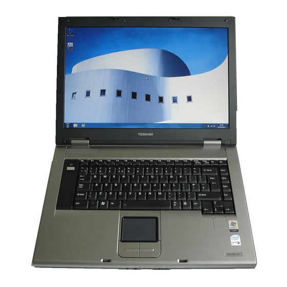
Page 19: Figure 1-1 Front Of The Computer
1.1 Features 1 Hardware Overview The front of the computer is shown in figure 1-1. Figure 1-1 Front of the computer TECRA A8 /Satellite Pro A120 Maintenance Manual (960-573) [CONFIDENTIAL]... -
Page 20: Figure 1-2 System Unit Configuration
1 Hardware Overview 1.1 Features The system unit configuration is shown in figure 1-2. Figure 1-2 System unit configuration [CONFIDENTIAL] TECRA A8 /Satellite Pro A120 Maintenance Manual (960-573) -
Page 21: Figure 1-3-1 System Unit Block Diagram (Intel Chipset Model)
1 Hardware Overview Figure 1-3-1, 1-3-2 is a block diagram of the system unit. Figure 1-3-1 System unit block diagram (Intel chipset model) Figure 1-3-2 System unit block diagram (ATI chipset model) TECRA A8 /Satellite Pro A120 Maintenance Manual (960-573) [CONFIDENTIAL]... - Page 22 – Integrated L1 cache memory of 64KB (32KB +32KB) – Integrated L2 cache memory of 1MB – Processor bus speed: 533MHz – Core voltage: Multiple VID – 478-pin Micro FC-PGA package [CONFIDENTIAL] TECRA A8 /Satellite Pro A120 Maintenance Manual (960-573)
- Page 23 – Internal Graphics Controller : Inter Generation 3.5 Integrated GFX Core (250MHz) – DMI(Direct Media Interface) – Supports ICH. – 1466-ball 37.5×37.5×2.56mm FC-BGA package • ATI RC420MD: – Graphic controller – System Memory controller : DDR2-400/DDR2-533/DDR2-667, 2GB(max) TECRA A8 /Satellite Pro A120 Maintenance Manual (960-573) [CONFIDENTIAL]...
- Page 24 − ACPI 2.0 compliant − Enhanced DMA Controller, Interrupt Controller, and Timer Functions − Integrated Serial ATA Host Controller (4 ports) − Integrated IDE controller supports Ultra ATA 100/66/33 (2 ports) 1-10 [CONFIDENTIAL] TECRA A8 /Satellite Pro A120 Maintenance Manual (960-573)
- Page 25 PC Card Controller (TI PCI7412) − PCI I/F − CardBus / Ultra media Controller (1 socket) − SD/MMC, Memory Stick, XD Card Controller − 1394 Controller (2 ports) – 288-ball, 16×16×1.4mm, BGA Package TECRA A8 /Satellite Pro A120 Maintenance Manual (960-573) [CONFIDENTIAL] 1-11...
- Page 26 − External microphone jack Modem Controller • Askey-made one MDC is used. • This controller has the following functions: – One RJ11 port – V.92 (V.90) 56K Modem/FAX – Supports Ring Wakeup 1-12 [CONFIDENTIAL] TECRA A8 /Satellite Pro A120 Maintenance Manual (960-573)
- Page 27 EC/KBC (Renesas-made M306KAFCLRP) • PSC (Toshiba-made TMP86FS49UG) • Super I/O (LPC-made 47N217) • Temperature sensor (ADM-made 1032ARMZ ×2) • Acceleration sensor (ST Micro-made LIS3L02AQ) • TPM (Infineon-made SLB9635 TT 1.2) TECRA A8 /Satellite Pro A120 Maintenance Manual (960-573) [CONFIDENTIAL] 1-13...
-
Page 28: Inch Hard Disk Drive
Speed (RPM) 5,400 Data transfer rate To/From media 61.3 max. To/From host 1.5 (150MB/s) max. Data buffer size (MB) Average seek time (ms) Read Motor startup time (s) 4 typ. 1-14 [CONFIDENTIAL] TECRA A8 /Satellite Pro A120 Maintenance Manual (960-573) - Page 29 61.3 MB/s max 629 Mb/s max. To/From host (Gbps) Data buffer size (KB) 8,192 8,192 Average seek time (ms) 12 typ 10 typ. Read Motor startup time (s) 4 typ. TECRA A8 /Satellite Pro A120 Maintenance Manual (960-573) [CONFIDENTIAL] 1-15...
-
Page 30: Keyboard
The keyboard is connected to membrane connector on the system board and controlled by the keyboard controller. Figure 1-5 is a view of the keyboard. See Appendix E about a layout of the keyboard. Figure 1-5 Keyboard 1-16 [CONFIDENTIAL] TECRA A8 /Satellite Pro A120 Maintenance Manual (960-573) -
Page 31: Optical Drive
33.3Mbytes/sec max. Burst 1,545 -3,600kB/sec Sustained Access time (ms) CD-ROM 110 typ. Supported Disks CD: CD/CD-ROM (12cm, 8cm), CD-R, CD-RW Supported Formats CD: CD-DA, CD-ROM, CD-ROM XA, PHOTO CD, Enhanced CD TECRA A8 /Satellite Pro A120 Maintenance Manual (960-573) [CONFIDENTIAL] 1-17... - Page 32 DVD:DVD-ROM, DVD-R, DVD-RW, DVD-RAM, DVD+R, DVD+RW Supported Formats CD: CD-DA, CD-ROM, CD-ROM XA, PHOTO CD, Enhanced CD, CD-text, Multi-session, Addressing method 2 DVD: DVD-ROM, DVD-R, DVD-RW,DVD- Video, DVD-R/RW(Single/Multi-session, Packet), DVD-RAM (2.6GB/4.7GB) 1-18 [CONFIDENTIAL] TECRA A8 /Satellite Pro A120 Maintenance Manual (960-573)
-
Page 33: Dvd-Rom & Cd-R/Rw Drive Specifications
180 typ. (Random) DVD-ROM 130 typ. (Random) Supported Formats CD: CD/CD-ROM (12cm,8cm), CD-R, CD- RW, CD-DA, CD-ROM XA, Photo CD, CD-Extra(CD+), CD-text DVD: DVD-ROM, DVD-R, DVD-RW (Ver1.2), DVD-Video, DVD+R, DVD+RW, DVD-RAM (2.6GB/4.7GB) TECRA A8 /Satellite Pro A120 Maintenance Manual (960-573) [CONFIDENTIAL] 1-19... -
Page 34: Dvd Super Multi Drive Specifications
CD: CD-ROM (12cm, 8cm), CD-R, CD-RW DVD: DVD-ROM, DVD-R, DVD-RW, DVD-RAM, DVD+RW Supported Formats CD: CD-DA, CD-ROM, CD-ROM XA, PHOTO CD, CD-Extra(CD+), CD-text DVD: DVD-R, DVD-RW (Ver. 1.1, 1.2), DVD-Video, DVD+R, DVD+RW, DVD-RAM (2.6GB/4.7GB) 1-20 [CONFIDENTIAL] TECRA A8 /Satellite Pro A120 Maintenance Manual (960-573) -
Page 35: Tft Color Display
Item 15.4inch WXGA TFT (LG G33C0003G110) Number of Dots 1,280(W) x 800(H) Dot spacing (mm) 0.258(H) x 0.258(V) Display range (mm) 331.2(H) x 207.0(V) Table 1-6 LCD module specifications (2/2) TECRA A8 /Satellite Pro A120 Maintenance Manual (960-573) [CONFIDENTIAL] 1-21... - Page 36 Display range (mm) 331.2(H) x 207.0(V) Specifications Item 15.4inch WXGA TFT (SAMSUNG G33C0003H110) Number of Dots 1,280(W) x 800(H) Dot spacing (mm) 0.258(H) x 0.258(V) Display range (mm) 331.2(H) x 207.0(V) 1-22 [CONFIDENTIAL] TECRA A8 /Satellite Pro A120 Maintenance Manual (960-573)
-
Page 37: Table
The FL inverter board supplies a high frequency current to illuminate the LCD module. Table 1-7 lists the FL inverter board specifications. Table 1-7 FL inverter board specifications Item Specifications G71C00011221 Input Voltage (VDC) Power (W) Output Voltage (Vrms) Current (mArms) Power (W/VA) TECRA A8 /Satellite Pro A120 Maintenance Manual (960-573) [CONFIDENTIAL] 1-23... -
Page 38: Power Supply
7. Calculates the remaining battery capacity. 8. Controls the transmission of the status signal of the main battery. The power supply output rating is specified in Table 1-8-1 and 1-8-2. 1-24 [CONFIDENTIAL] TECRA A8 /Satellite Pro A120 Maintenance Manual (960-573) -
Page 39: Table 1-8-1 Power Supply Output Rating (Intel Chipset Model)
Yes / No ICH7-M, ODD, HDD, PC- Card Power, LED, KB, PAD, CRT, FAN, FL-Inv Yes / No ICH7-M, USB Power SND-P5V AN12941A A4R7-P4V AD1981HD, AN12941A 2.0 -3.5 ICH7-M (RTC) TECRA A8 /Satellite Pro A120 Maintenance Manual (960-573) [CONFIDENTIAL] 1-25... -
Page 40: Table 1-8-2 Power Supply Output Rating (Ati Chipset Model) (1/2
Bluetooth LAN-E3V Yes / No LAN2R5-E2V Yes / No South Bridge, ODD, SATA- HDD, PC-Card Power, LED, KB, PAD, Parallel, CRT, FAN, LCD power Yes / No USB Power, MDC 1-26 [CONFIDENTIAL] TECRA A8 /Satellite Pro A120 Maintenance Manual (960-573) -
Page 41: Table
Power OFF (Suspend batter Object e[V] (Boot mode) mode) FL-P5V FL-Inverter PNL-P3V DDC-P5V IF-P5V Docker SND-P5V AMP, Sound Power MCVCCA-PYV PC card MCVPPA-PYV PC card A4R7-P4V Sound CODEC, AMP SP-P5V 2.0-3.5 TECRA A8 /Satellite Pro A120 Maintenance Manual (960-573) [CONFIDENTIAL] 1-27... -
Page 42: Batteries
Table 1-10 Time required for charges Battery type Power on (hours) Power off (hours) Main battery (3,600 mAh) About 4.5 to 10.0 About 3.0 Main battery (4,400 mAh) About 5.5 to 12.0 About 3.0 1-28 [CONFIDENTIAL] TECRA A8 /Satellite Pro A120 Maintenance Manual (960-573) -
Page 43: Data Preservation Time
Table 1-12 lists the charging time and data preservation period of the RTC battery. Table 1-12 RTC battery charging/data preservation time Status Time Charging Time (power on) 8 hours Data preservation period (full charge) 30 days TECRA A8 /Satellite Pro A120 Maintenance Manual (960-573) [CONFIDENTIAL] 1-29... -
Page 44: Ac Adaptor
Power 60W (Peak 75W) Input voltage 100V/240V Input frequency 50Hz to 60Hz Input current 1.5A or less (100V-240V 4Aload) Output voltage Output current 0A to 4A (At constant voltage mode) 1-30 [CONFIDENTIAL] TECRA A8 /Satellite Pro A120 Maintenance Manual (960-573) -
Page 45: Chapter 2 Troubleshooting Procedures
Chapter 2 Troubleshooting Procedures [CONFIDENTIAL]... - Page 46 2 Troubleshooting Procedures 2-ii [CONFIDENTIAL] TECRA A8 /Satellite Pro A120 Maintenance Manual (960-573)
- Page 47 Modem Troubleshooting ..................2-60 2.11 LAN Troubleshooting ....................2-62 2.12 Bluetooth Troubleshooting..................2-63 2.13 Wireless LAN Troubleshooting ................2-65 2.14 Sound Troubleshooting ....................2-67 2.15 SD card Slot Troubleshooting ..................2-70 2.16 Fingerprint sensor Troubleshooting .................2-71 TECRA A8 /Satellite Pro A120 Maintenance Manual (960-573) [CONFIDENTIAL] 2-iii...
-
Page 48: Tables
Table 2-4-1 Debug port (Boot mode) error status...............2-25 Table 2-4-2 Debug port (Boot mode) error status...............2-34 Table 2-5 FDD error code and status................2-46 Table 2-6 HDD error code and status ................2-51 2-iv [CONFIDENTIAL] TECRA A8 /Satellite Pro A120 Maintenance Manual (960-573) -
Page 49: Troubleshooting
2. Implements for debugging port check • Toshiba DOS system FD • RS-232C cross cable • Test board with debug port test cable • PC for displaying debug port test result TECRA A8 /Satellite Pro A120 Maintenance Manual (960-573) [CONFIDENTIAL]... - Page 50 2.3 Power Supply Troubleshooting. (1) Cable connection is described in the figure as line. (2) Pin connection is described in the figure as arrow. <e.g> Connection of modem [CONFIDENTIAL] TECRA A8 /Satellite Pro A120 Maintenance Manual (960-573)
-
Page 51: Troubleshooting Flowchart
Make sure that Windows XP preinstalled by Toshiba is installed on the hard disk. Operating systems not preinstalled by Toshiba can cause the computer malfunction. Make sure all optional equipment is removed from the computer. Make sure the USB FDD (When connected to the computer) and optical drive are empty. - Page 52 2 Troubleshooting Procedures 2.2 Troubleshooting Flowchart Figure 2-1 Troubleshooting flowchart (1/2) [CONFIDENTIAL] TECRA A8 /Satellite Pro A120 Maintenance Manual (960-573)
- Page 53 2.2 Troubleshooting Flowchart 2 Troubleshooting Procedures Figure 2-1 Troubleshooting flowchart (2/2) TECRA A8 /Satellite Pro A120 Maintenance Manual (960-573) [CONFIDENTIAL]...
- Page 54 12. If a malfunction is detected on SD card, perform the SD card slot Troubleshooting Procedures in Section 2.15. 13. If a malfunction is detected on Fingerprint sensor, perform the Fingerprint sensor Troubleshooting Procedures in Section 2.16. [CONFIDENTIAL] TECRA A8 /Satellite Pro A120 Maintenance Manual (960-573)
-
Page 55: Power Supply Troubleshooting
(even intervals) Blinks orange once The system is driven by only a battery and the battery level (at being switched on) is low. Doesn’t light Any condition other than those above. TECRA A8 /Satellite Pro A120 Maintenance Manual (960-573) [CONFIDENTIAL]... - Page 56 If the DC IN icon does not light, go to Procedure 3. Check 3 If the battery icon does not light orange or blue, go to Procedure 4. NOTE: Use a supplied AC adapter G71C0004A510 (3-pin)/ G71C0002SC10 (2-pin). [CONFIDENTIAL] TECRA A8 /Satellite Pro A120 Maintenance Manual (960-573)
- Page 57 Where Error occurs AC Adaptor 1st Battery 2nd Battery S3V output E5V output E3V output 1R5-E1V output 1R8-B1V output PPV output PTV output 1R5-E1V output 1R8-B1V output PPV output PTV output TECRA A8 /Satellite Pro A120 Maintenance Manual (960-573) [CONFIDENTIAL]...
- Page 58 S3V voltage is 3.47V or less when the computer is powered on/off. S3V voltage is under 3.14V in normal conditions. S3V voltage is under 3.14V when the computer is booting up. 2-10 [CONFIDENTIAL] TECRA A8 /Satellite Pro A120 Maintenance Manual (960-573)
- Page 59 1R8-B1V voltage is under 1.53V when the computer is powered on. 1R8-B1V voltage is under 1.53V when the computer is booting up. 1R8-B1V voltage is under 1.53V when BV power is maintained and OUTV4=BV is designated. TECRA A8 /Satellite Pro A120 Maintenance Manual (960-573) [CONFIDENTIAL] 2-11...
- Page 60 PPV voltage is over 1.80V when the computer is powered on/off. PPV voltage is under 0.32V when the computer is powered on. PPV voltage is under 0.32V when the computer is booting up. 2-12 [CONFIDENTIAL] TECRA A8 /Satellite Pro A120 Maintenance Manual (960-573)
- Page 61 Where Error occurs AC Adaptor 1st Battery 2nd Battery S3V output E5V output E3V output PMV output 1R8-B1V output PPV output PTV output PMV output 1R8-B1V output PPV output PTV output TECRA A8 /Satellite Pro A120 Maintenance Manual (960-573) [CONFIDENTIAL] 2-13...
- Page 62 S3V voltage is 3.47V or less when the computer is powered on/off. S3V voltage is under 3.14V in normal conditions. S3V voltage is under 3.14V when the computer is booting up. 2-14 [CONFIDENTIAL] TECRA A8 /Satellite Pro A120 Maintenance Manual (960-573)
- Page 63 1R8-B1V voltage is under 1.53V when the computer is powered on. 1R8-B1V voltage is under 1.53V when the computer is booting up. 1R8-B1V voltage is under 1.53V when BV power is maintained and OUTV4=BV is designated. TECRA A8 /Satellite Pro A120 Maintenance Manual (960-573) [CONFIDENTIAL] 2-15...
- Page 64 PPV voltage is over 1.80V when the computer is powered on/off. PPV voltage is under 0.32V when the computer is powered on. PPV voltage is under 0.32V when the computer is booting up. 2-16 [CONFIDENTIAL] TECRA A8 /Satellite Pro A120 Maintenance Manual (960-573)
- Page 65 Make sure the battery pack is correctly installed in the computer. If the battery pack is correctly installed, go to Procedure3. Check 4 For any other error, go to Procedure 5. TECRA A8 /Satellite Pro A120 Maintenance Manual (960-573) [CONFIDENTIAL] 2-17...
- Page 66 Check 6 Make sure the battery pack is installed in the computer correctly. If the battery is properly installed and the battery icon still does not light, go to Procedure 4. 2-18 [CONFIDENTIAL] TECRA A8 /Satellite Pro A120 Maintenance Manual (960-573)
- Page 67 If the battery pack still is not charged, go to Check 5. Check 5 Replace the battery pack with a new one. If the battery pack still is not charged, go to Procedure 5. TECRA A8 /Satellite Pro A120 Maintenance Manual (960-573) [CONFIDENTIAL] 2-19...
- Page 68 Battery pack may be faulty. Replace it with a new one. If the problem still occurs, perform Check 2. Check 2 System board may be faulty. Replace it with a new one. 2-20 [CONFIDENTIAL] TECRA A8 /Satellite Pro A120 Maintenance Manual (960-573)
-
Page 69: System Board Troubleshooting
The procedures described in this section are: Procedure 1: Message Check Procedure 2: Debugging Port Check (Boot Mode) Procedure 3: Diagnostic Test Program Execution Check Procedure 4: Replacement Check TECRA A8 /Satellite Pro A120 Maintenance Manual (960-573) [CONFIDENTIAL] 2-21... - Page 70 Go to Procedure 3. WARNING: RESUME FAILURE. PRESS ANY KEY TO CONTINUE. If any other error message displays, perform Check 3. 2-22 [CONFIDENTIAL] TECRA A8 /Satellite Pro A120 Maintenance Manual (960-573)
- Page 71 DMAC #2 ERROR (14) PIC #1 ERROR (15) PIC #2 ERROR (16) KBC ERROR (17) HDC ERROR (18) Built-in HDD ERROR (19) CD-ROM ERROR (20) TIMER INTERRUPT ERROR (21) RTC UPDATE ERROR TECRA A8 /Satellite Pro A120 Maintenance Manual (960-573) [CONFIDENTIAL] 2-23...
- Page 72 6. When the D port status is FFFF (normal status), go to Procedure 4. When the D port status falls into any other status than FFFF, go to Procedure 3. 2-24 [CONFIDENTIAL] TECRA A8 /Satellite Pro A120 Maintenance Manual (960-573)
- Page 73 Transits to System BIOS IRT BIOS rewrite process Initialization of ICHM. D31 Configuration of DRAM Permission of cache (L1 cache only) Memory clear F008 Transition to real mode and copy of BIOS to RAM TECRA A8 /Satellite Pro A120 Maintenance Manual (960-573) [CONFIDENTIAL] 2-25...
- Page 74 Reading of EXE header of “CHGBIOSA.EXE” and “CHGFIRMA.EXE” Key input when error occurred Execution of “CHGBIOSA.EXE” and “CHGFIRMA.EXE” F100 Prohibition of cache Permission of L1/L2 cache in Flash ROM area Renewal of microcode 2-26 [CONFIDENTIAL] TECRA A8 /Satellite Pro A120 Maintenance Manual (960-573)
-
Page 75: Table
Resume error F173H RSM_SMRAM_ERR RAM area checksum check in system BIOS Resume error F179H SM_RAMBIOS_ERR Expansion memory checksum check Resume error F176H RSM_EXTMEM_ERR PnP RAM checksum check Resume error F177H RSM_PNPRAM_ERR TECRA A8 /Satellite Pro A120 Maintenance Manual (960-573) [CONFIDENTIAL] 2-27... - Page 76 Test of PIT channel 2 (Check whether the speaker gate works normally) CPU clock measurement Check of parameter block A Permission of SMI except auto-off function Judgment of destination (country) from DMI data 2-28 [CONFIDENTIAL] TECRA A8 /Satellite Pro A120 Maintenance Manual (960-573)
- Page 77 HC initialization, device connection recognition Recognition of SD memory card and initialization Initialization of PIC Test of PIC Initialization of Password F108 PCI bus initialization Initialization of LAN information Check of WakeUp factor TECRA A8 /Satellite Pro A120 Maintenance Manual (960-573) [CONFIDENTIAL] 2-29...
-
Page 78: Table
Output code generation (Check of first 64KB memory) F10C FIRST_64KB_CHECK F10D INIT_INT_VECTOR (Initialization of vectors) (Initialization of NDP) F10E INIT_NDP INIT_SYSTEM Storing of CMOS error status to F10F (Initialization of system) IRT_ERR_STS_BUF 2-30 [CONFIDENTIAL] TECRA A8 /Satellite Pro A120 Maintenance Manual (960-573) -
Page 79: Table
Initialization of ATA priority in Boot mode Key input check during IRT (waiting here completion of KBC initialization) Input password (Waiting completion of HDD initialization) I/O LOCK process (model supporting I/O LOCK) TECRA A8 /Satellite Pro A120 Maintenance Manual (960-573) [CONFIDENTIAL] 2-31... - Page 80 Hibernation branch (for models supporting BIOS Hibernation) Initialization of Bluetooth (for models supporting Bluetooth) Check for existence of target maintenance card Prohibition of unused PC card not used Setting Wakeup status data for ACPI 2-32 [CONFIDENTIAL] TECRA A8 /Satellite Pro A120 Maintenance Manual (960-573)
- Page 81 Final decision of USB FDD drive information Post processing of PRE_BOOT_SETUP Clear of PWRBTN_STS Enabling POWER Button F122 Initialization of SC F124 Clears IRT status Renewal of checksum of Runtime side. FFFF TECRA A8 /Satellite Pro A120 Maintenance Manual (960-573) [CONFIDENTIAL] 2-33...
- Page 82 Transits to System BIOS IRT BIOS rewrite process Initialization of South Bridge Configuration of DRAM Permission of cache (L1 cache only) Memory clear Transition to real mode and copy of BIOS to 2-34 [CONFIDENTIAL] TECRA A8 /Satellite Pro A120 Maintenance Manual (960-573)
- Page 83 Reading of EXE header of “CHGBIOSA.EXE” and “CHGFIRMA.EXE” Key input when error occurred Execution of “CHGBIOSA.EXE” and “CHGFIRMA.EXE” F100 Prohibition of cache Permission of L1/L2 cache in Flash ROM area Renewal of microcode TECRA A8 /Satellite Pro A120 Maintenance Manual (960-573) [CONFIDENTIAL] 2-35...
-
Page 84: Table
Resume error F173H RSM_SMRAM_ERR RAM area checksum check in system BIOS Resume error F179H SM_RAMBIOS_ERR Expansion memory checksum check Resume error F176H RSM_EXTMEM_ERR PnP RAM checksum check Resume error F177H RSM_PNPRAM_ERR 2-36 [CONFIDENTIAL] TECRA A8 /Satellite Pro A120 Maintenance Manual (960-573) - Page 85 Test of PIT channel 2 (Check whether the speaker gate works normally) CPU clock measurement Check of parameter block A Permission of SMI except auto-off function Judgment of destination (country) from DMI data TECRA A8 /Satellite Pro A120 Maintenance Manual (960-573) [CONFIDENTIAL] 2-37...
- Page 86 PC multi-box status acquisition ( model supporting select bay) HC initialization, device connection recognition Recognition of SD memory card and initialization F108 PCI bus initialization Initialization of LAN information Check of WakeUp factor 2-38 [CONFIDENTIAL] TECRA A8 /Satellite Pro A120 Maintenance Manual (960-573)
-
Page 87: Table
Output code generation (Check of first 64KB memory) F10C FIRST_64KB_CHECK F10D INIT_INT_VECTOR (Initialization of vectors) (Initialization of NDP) F10E INIT_NDP INIT_SYSTEM Storing of CMOS error status to F10F (Initialization of system) IRT_ERR_STS_BUF TECRA A8 /Satellite Pro A120 Maintenance Manual (960-573) [CONFIDENTIAL] 2-39... -
Page 88: Table
Initialization of ATA priority in Boot mode Key input check during IRT (waiting here completion of KBC initialization) Input password (Waiting completion of HDD initialization) I/O LOCK process (model supporting I/O LOCK) 2-40 [CONFIDENTIAL] TECRA A8 /Satellite Pro A120 Maintenance Manual (960-573) - Page 89 Hibernation branch (for models supporting BIOS Hibernation) Initialization of Bluetooth (for models supporting Bluetooth) Check for existence of target maintenance card Prohibition of unused PC card not used Setting Wakeup status data for ACPI TECRA A8 /Satellite Pro A120 Maintenance Manual (960-573) [CONFIDENTIAL] 2-41...
- Page 90 Initialization of SC F124 Clears IRT status Renewal of checksum of Runtime side. FFFF NOTE: Status outputted by the test means the last error detected in the debug port test. 2-42 [CONFIDENTIAL] TECRA A8 /Satellite Pro A120 Maintenance Manual (960-573)
- Page 91 10. Expansion test 11. CD-ROM/DVD-ROM test 12. Only One test 13. Wireless LAN test 14. Sound test 15. LAN/Modem/Bluetooth/IEEE1394 test If an error is detected during these tests, go to Procedure 4. TECRA A8 /Satellite Pro A120 Maintenance Manual (960-573) [CONFIDENTIAL] 2-43...
- Page 92 2.4 System Board Troubleshooting Procedure 4 Replacement Check The system board connectors may be faulty. Disassemble the computer following the steps described in Chapter 4, Replacement Procedures and replace it. 2-44 [CONFIDENTIAL] TECRA A8 /Satellite Pro A120 Maintenance Manual (960-573)
-
Page 93: Usb Fdd Troubleshooting
Clean the USB FDD heads using the cleaning kit. If the USB FDD still does not function properly after cleaning, go to Procedure If the test program cannot be executed, go to Procedure 3. TECRA A8 /Satellite Pro A120 Maintenance Manual (960-573) [CONFIDENTIAL] 2-45... - Page 94 If the following message appears, disable the write protect tab on the floppy disk. If any other message appears, perform Check 2. Write protected Check 2 Make sure the floppy disk is formatted correctly. If it is, go to Procedure 3. 2-46 [CONFIDENTIAL] TECRA A8 /Satellite Pro A120 Maintenance Manual (960-573)
- Page 95 If the USB FDD is still not functioning properly, perform Check 3. Check 3 Replace the System board with a new one following the steps in Chapter 4, Replacement Procedures. TECRA A8 /Satellite Pro A120 Maintenance Manual (960-573) [CONFIDENTIAL] 2-47...
-
Page 96: Hdd Troubleshooting
Procedure 1 Partition Check Insert the Toshiba DOS system disk and restart the computer with U key holding down. Perform the following checks: Check 1 Type C: and press Enter. If you cannot change to drive C, go to Check 2. If you can change to drive C, go to Procedure 2. - Page 97 2.5” HDD(s) and the connector(s) of system board may be defective (Refer to the steps described in Chapter 4, Replacement Procedures for disassembling.). Insert HDD(s) to the connector(s) firmly. If it is (or they are) firmly connected, go to Procedure 3. TECRA A8 /Satellite Pro A120 Maintenance Manual (960-573) [CONFIDENTIAL] 2-49...
- Page 98 If HDD is formatted, set the 2.5” HDD partition using DOS FDISK command. If you cannot format the 2.5” HDD using the Tests and Diagnostic program, go to Procedure 4. 2-50 [CONFIDENTIAL] TECRA A8 /Satellite Pro A120 Maintenance Manual (960-573)
- Page 99 Bad track error ECC error ECC recover enable DMA CRC error HDC error Seek error Time out error Drive not ready Undefined error Write fault Status error Access time error No HDD TECRA A8 /Satellite Pro A120 Maintenance Manual (960-573) [CONFIDENTIAL] 2-51...
- Page 100 Chapter 4, Replacement Procedures. If the problem still exists, perform Check Check 3 The System board may be damaged. Replace it with a new one following the instructions in Chapter 4, Replacement Procedures. 2-52 [CONFIDENTIAL] TECRA A8 /Satellite Pro A120 Maintenance Manual (960-573)
-
Page 101: Keyboard And Touch Pad Troubleshooting
Diagnostics, for more information on how to perform the test program. If an error occurs, go to Procedure 2. If an error does not occur, the keyboard is functioning properly. TECRA A8 /Satellite Pro A120 Maintenance Manual (960-573) [CONFIDENTIAL] 2-53... - Page 102 Check 4 The touch pad may be damaged. Replace it with a new one following the instructions in Chapter 4, Replacement Procedures. If the problem still exists, perform Check 5. 2-54 [CONFIDENTIAL] TECRA A8 /Satellite Pro A120 Maintenance Manual (960-573)
- Page 103 Chapter 4, Replacement Procedures. If the problem still exists, perform Check 8. Check 8 The system board may be damaged. Replace it with a new one following the instructions in Chapter 4, Replacement Procedures. TECRA A8 /Satellite Pro A120 Maintenance Manual (960-573) [CONFIDENTIAL] 2-55...
-
Page 104: Display Troubleshooting
Chapter 4, Replacement Procedures. If the connection is loose, reconnect firmly and restart the computer. If there is still an error, go to Procedure 3. 2-56 [CONFIDENTIAL] TECRA A8 /Satellite Pro A120 Maintenance Manual (960-573) - Page 105 Check 4 Check 4 The display controller on the system board may be damaged. Replace the system board with a new one following the instructions in Chapter 4, Replacement Procedures. TECRA A8 /Satellite Pro A120 Maintenance Manual (960-573) [CONFIDENTIAL] 2-57...
-
Page 106: Optical Drive Troubleshooting
Refer to Chapter 3, Tests and Diagnostics, for more information about the diagnostics test procedures. If any errors occur while executing the CD-ROM/DVD-ROM test, go to Procedure 2. 2-58 [CONFIDENTIAL] TECRA A8 /Satellite Pro A120 Maintenance Manual (960-573) - Page 107 The drive may be defective or damaged. Replace the drive with a new one. If there is still an error, go to Check 3. Check 3 Replace the system board with a new one following the steps in Chapter 4, Replacement Procedures. TECRA A8 /Satellite Pro A120 Maintenance Manual (960-573) [CONFIDENTIAL] 2-59...
-
Page 108: Modem Troubleshooting
Refer to Chapter 3, Tests and Diagnostics, for more information about the diagnostics test procedures. If any errors occur while executing the Sound/Modem/LAN test, go to Procedure 2. 2-60 [CONFIDENTIAL] TECRA A8 /Satellite Pro A120 Maintenance Manual (960-573) - Page 109 Check 4. Check 4 The system board may be defective or damaged. Replace it with a new one following the steps in Chapter 4, Replacement Procedures. TECRA A8 /Satellite Pro A120 Maintenance Manual (960-573) [CONFIDENTIAL] 2-61...
-
Page 110: Lan Troubleshooting
LAN function is still not functioning properly, perform Check 2. Check 2 The system board may be defective or damaged. Replace it with a new one following the steps in Chapter 4, Replacement Procedures. 2-62 [CONFIDENTIAL] TECRA A8 /Satellite Pro A120 Maintenance Manual (960-573) -
Page 111: Bluetooth Troubleshooting
Chapter 3, Bluetooth Test Program. You will need a second computer that can communicate by the Bluetooth. If the computer passes the test, the function is correctly working. If the computer does not pass the test, perform Procedure 2. TECRA A8 /Satellite Pro A120 Maintenance Manual (960-573) [CONFIDENTIAL] 2-63... - Page 112 Procedures. If the Bluetooth is still not functioning properly, perform Check 3. Check 3 The system board may be defective or damaged. Replace the system board with a new one following the steps in Chapter 4, Replacement Procedures. 2-64 [CONFIDENTIAL] TECRA A8 /Satellite Pro A120 Maintenance Manual (960-573)
-
Page 113: Wireless Lan Troubleshooting
LAN. You will need a second computer that can communicate by the wireless LAN. If the computer passes the test, the function is correctly working. If the computer does not pass the test, perform Procedure 2. TECRA A8 /Satellite Pro A120 Maintenance Manual (960-573) [CONFIDENTIAL] 2-65... - Page 114 Check 3 The system board may be defective or damaged. Replace the board with a new one following the instructions in Chapter 4, Replacement Procedures and test the display again. 2-66 [CONFIDENTIAL] TECRA A8 /Satellite Pro A120 Maintenance Manual (960-573)
-
Page 115: Sound Troubleshooting
Insert the Sound test program in the USB floppy disk drive, turn on the computer and run the test. Refer to Chapter 3, Tests and Diagnostics, for details. If an error is detected, go to Procedure 2. TECRA A8 /Satellite Pro A120 Maintenance Manual (960-573) [CONFIDENTIAL] 2-67... - Page 116 Make sure the external microphone cable is firmly connected to J6051 on the system board. If the external microphones are still not functioning properly, go to Procedure 3. 2-68 [CONFIDENTIAL] TECRA A8 /Satellite Pro A120 Maintenance Manual (960-573)
- Page 117 Check 2. Check 2 If the headphone or external microphone does not sound properly, the system board may be defective or damaged. Replace the system board with a new one. TECRA A8 /Satellite Pro A120 Maintenance Manual (960-573) [CONFIDENTIAL] 2-69...
-
Page 118: Sd Card Slot Troubleshooting
Chapter 4 Replacement Procedures. If the problem continues, perform Check 4. Check 3 The system board may be faulty. Replace it with a new one following the step in Chapter 4 Replacement Procedures. 2-70 [CONFIDENTIAL] TECRA A8 /Satellite Pro A120 Maintenance Manual (960-573) -
Page 119: Fingerprint Sensor Troubleshooting
2. Slide slowly your finger from the first joint to fingertip at constant speed. When not recognized, adjust the speed. Fingerprint Fingerprint sensor sensor TECRA A8 /Satellite Pro A120 Maintenance Manual (960-573) [CONFIDENTIAL] 2-71... - Page 120 Registration of fingerprint 1. Logon by user’s account to register the fingerprint. 2. Open [Start] → [All Programs] → [Protector Suite QL] → [User Enrollment]. 3. After displaying [User Enrollment], click [Next]. 2-72 [CONFIDENTIAL] TECRA A8 /Satellite Pro A120 Maintenance Manual (960-573)
- Page 121 When the finger print has been enrolled, [User’s Password] appears. Slide your finger enrolled or type the password. Click [Next]. 4. Type the Windows logon password in “Enter your password” and click [Next]. [User’s Password] appears. TECRA A8 /Satellite Pro A120 Maintenance Manual (960-573) [CONFIDENTIAL] 2-73...
- Page 122 2.16 Fingerprint sensor Troubleshooting 5. Confirm that the box of [Run interactive tutorial] is checked (when proceeding wit seeing Tutorial) and click [Next]. 6. Watch the Video carefully, click [Next]. 2-74 [CONFIDENTIAL] TECRA A8 /Satellite Pro A120 Maintenance Manual (960-573)
- Page 123 Slide your finger four times. Four boxes are filled with fingerprints. At this time, when you click the [Replay video], you can watch the video that you have watched in Procedure 6. TECRA A8 /Satellite Pro A120 Maintenance Manual (960-573) [CONFIDENTIAL] 2-75...
- Page 124 [Try again]. When you have fully succeeded in four times of reading, the message of “Fully succeeded” appears. 8. Click [Next]. The display of [User’s Fingers] 9. Click the box you want to enroll. 2-76 [CONFIDENTIAL] TECRA A8 /Satellite Pro A120 Maintenance Manual (960-573)
- Page 125 10. Enroll another finger in Procedure 9. Enroll two fingers at least. 11. The display that recommend you to register a password. 12. Click [OK] in the following display. TECRA A8 /Satellite Pro A120 Maintenance Manual (960-573) [CONFIDENTIAL] 2-77...
- Page 126 13. Type a backup password two times in the following display. (This password is different from the password of Windows logon.) 14. Click [Next]. The [Finish] display appears. 15. Click [Finish], “Welcome” display appears. 2-78 [CONFIDENTIAL] TECRA A8 /Satellite Pro A120 Maintenance Manual (960-573)
- Page 127 When not authenticated well, warning message appears. If you fail continually ten times or more, you can not use the fingerprint authentication about one minute. When not authenticated, type the password to logon to Windows. TECRA A8 /Satellite Pro A120 Maintenance Manual (960-573) [CONFIDENTIAL] 2-79...
- Page 128 The Fingerprint sensor board may be faulty. Replace it with a new one. If the problem persists, perform Check 4. Check 4 The system board may be faulty. Replace it with a new one. 2-80 [CONFIDENTIAL] TECRA A8 /Satellite Pro A120 Maintenance Manual (960-573)
-
Page 129: Chapter 3 Tests And Diagnostics
Chapter 3 Tests and Diagnostics [CONFIDENTIAL]... - Page 130 3 Tests and Diagnostics 3-ii [CONFIDENTIAL] TECRA A8 /Satellite Pro A120 Maintenance Manual (960-573)
- Page 131 CD-ROM/DVD-ROM Test ..................3-34 3.18 Error Code and Error Status Names................. 3-35 3.19 Hard Disk Test Detail Status..................3-38 3.20 ONLY ONE TEST....................3-40 3.20.1 Program Description ................3-40 3.20.2 Operations ..................3-40 TECRA A8 /Satellite Pro A120 Maintenance Manual (960-573) [CONFIDENTIAL] 3-iii...
- Page 132 IEEE1394 test..................3-83 3.29 Sound Test program....................3-84 3.29.1 Sound (Standard) test ................. 3-84 3.29.2 Sound (Legacy) test................3-86 3.29.3 CD Sound (Standard) test..............3-87 3.29.4 CD Sound (Legacy) test ..............3-89 3-iv [CONFIDENTIAL] TECRA A8 /Satellite Pro A120 Maintenance Manual (960-573)
-
Page 133: Table
Table 3-5 Error message....................3-75 Table 3-6 Error code for Bluetooth test (BD_ADDR) ............3-76 Table 3-7 Error code for Bluetooth test (BD_ADDR of the DUT)........3-80 Table 3-8 Common error code ................... 3-82 TECRA A8 /Satellite Pro A120 Maintenance Manual (960-573) [CONFIDENTIAL]... - Page 134 3 Tests and Diagnostics 3-vi [CONFIDENTIAL] TECRA A8 /Satellite Pro A120 Maintenance Manual (960-573)
-
Page 135: The Diagnostic Test
POWER OFF The DIAGNOSTIC TEST MENU contains the following functional tests: SYSTEM TEST MEMORY TEST KEYBOARD TEST DISPLAY TEST FLOPPY DISK TEST PRINTER TEST ASYNC TEST HARD DISK TEST REAL TIMER TEST TECRA A8 /Satellite Pro A120 Maintenance Manual (960-573) [CONFIDENTIAL]... - Page 136 A USB test module (USB test ) A USB cable (USB test) An external CRT monitor (Expansion test) A CD test media TOSHIBA CD-ROM TEST DISK or ABEX TEST CD-ROM (Sound test) A DVD test media (DVD-ROM TEST DISK TSD-1) (Sound test)
- Page 137 The Diagnostics Disk (Main T&D) 3.1.3 Heatrun test program The heatrun test starts automatically after the selection. You will need the following equipment to perform this program. The Diagnostics Disk (Main T&D) TECRA A8 /Satellite Pro A120 Maintenance Manual (960-573) [CONFIDENTIAL]...
-
Page 138: Executing The Diagnostic Test
3.3 Setting of the hardware configuration. 2. Before replacing, apply the DMI information by executing subtest 04 DMI information recovery and subtest 08 System configuration in 3.3 Setting of the hardware configuration. [CONFIDENTIAL] TECRA A8 /Satellite Pro A120 Maintenance Manual (960-573) -
Page 139: Diagnostics Menu (T&D)
NOTE: To exit the DIAGNOSTIC TEST MENU, press the Esc key. If a test program is in progress, press Ctrl + Break to exit the test program. If a test program is in progress, press Ctrl + C to stop the test program. TECRA A8 /Satellite Pro A120 Maintenance Manual (960-573) [CONFIDENTIAL]... - Page 140 (0-255). To exit the submenu of the Diagnostic Test and returns to the Diagnostics Menu, set the highlight bar to function 99 and press Enter. [CONFIDENTIAL] TECRA A8 /Satellite Pro A120 Maintenance Manual (960-573)
- Page 141 Use the up and down arrow keys to move the cursor to “ERROR STOP”. Use the right and left arrow keys to move the cursor to the desired option and press Enter. TECRA A8 /Satellite Pro A120 Maintenance Manual (960-573) [CONFIDENTIAL]...
-
Page 142: H/W Initial Information Setting Tool
3.2.3 Heatrun test program After selecting this test, the heatrun test starts executing the same subtest as 3.23 RUNNING TEST. For more details on this test, refer to the section 3.4. [CONFIDENTIAL] TECRA A8 /Satellite Pro A120 Maintenance Manual (960-573) -
Page 143: Setting Of The Hardware Configuration
5. “Enter Bundle Number ?” is displayed. Input the computer’s PCN/Bundle number and press Enter. (e.g. PMSREQ3Q34H/S0123456789) 6. “Write data OK (Y/N) ?” is displayed. To write the DMI information to the Flash ROM, press Y, and then Enter. TECRA A8 /Satellite Pro A120 Maintenance Manual (960-573) [CONFIDENTIAL]... - Page 144 For more details on the system configuration information, refer to “3.25 System configuration”. Subtest 09 E2PROM test (MAC/GUID/DMI) It checks whether the MAC address, GUID of IEEE1394 and DMI information are written. 3-10 [CONFIDENTIAL] TECRA A8 /Satellite Pro A120 Maintenance Manual (960-573)
-
Page 145: Heatrun Test
NOTE: The test result (Errorlog.txt) is stored in the floppy disk. The result is displayed in the same format as Log Utilities. For more details of the format, refer to 3.22 Log Utilities. TECRA A8 /Satellite Pro A120 Maintenance Manual (960-573) [CONFIDENTIAL] 3-11... -
Page 146: Subtest Names
Gradation & Mode test for VGA All dot on/off for LCD “H” pattern display LCD Brightness FLOPPY DISK Sequential read Sequential read/write Random address/data Write specified address Read specified address 3-12 [CONFIDENTIAL] TECRA A8 /Satellite Pro A120 Maintenance Manual (960-573) - Page 147 W-R-C specified address REAL TIMER Real time Backup memory Real time carry EXPANSION PCMCIA wraparound [Not supported] RGB monitor ID CD-ROM Sequential read /DVD-ROM Read specified address Random address/data RW 1point W/R/C TECRA A8 /Satellite Pro A120 Maintenance Manual (960-573) [CONFIDENTIAL] 3-13...
-
Page 148: System Test
After a while, the fan rotating will stop. is not supported in this model. 2;FAN#2(GPU) Subtest 03 Geyserville If the CPU supports Gerserville (SpeedStep), this subtest checks that the CPU operating clock speed can be changed. 3-14 [CONFIDENTIAL] TECRA A8 /Satellite Pro A120 Maintenance Manual (960-573) - Page 149 : XXXXXXXXXXXX Serial Number : XXXXXXXX Model Number : XXXXXX-XXXXX UUID Number : XXXXXXXXXXXXXXXXXXXXXXXXXXXXXXXX Press [Enter] to EXIT To exit this subtest and return to the SYSTEM test menu, press Enter. TECRA A8 /Satellite Pro A120 Maintenance Manual (960-573) [CONFIDENTIAL] 3-15...
-
Page 150: Memory Test
Data: FFh, FFh, FFh, FFh, FFh, 00h, 00h, 00h, 00h, FFh, FFh, FFh, 00h, FFh, 00h, 00h, FFh, 00h, 00h, FFh, FFh, FFh, FFh, 00h, 00h, 00h, AAh 3-16 [CONFIDENTIAL] TECRA A8 /Satellite Pro A120 Maintenance Manual (960-573) -
Page 151: Keyboard Test
Appendix E. KEYBOARD TEST IN PROGRESS 302000 Scan code Character code Keytop Ins Lock Caps Lock Num Lock Scroll Lock Ctrl Left Shift Right Shift PRESS [Enter] KEY TECRA A8 /Satellite Pro A120 Maintenance Manual (960-573) [CONFIDENTIAL] 3-17... -
Page 152: Display Test
This subtest displays bands of gradations for mixed colors, then for red, green, and blue. Next, it displays eight solid colors full screen: red, semi-red, green, semi-green, blue, semi-blue, white and semi-white. Each color displays for three seconds. 3-18 [CONFIDENTIAL] TECRA A8 /Satellite Pro A120 Maintenance Manual (960-573) - Page 153 All dot on/off for LCD This subtest displays an all-white screen then an all-black screen. The display changes automatically every three seconds and the screen returns to the DISPLAY TEST menu. TECRA A8 /Satellite Pro A120 Maintenance Manual (960-573) [CONFIDENTIAL] 3-19...
- Page 154 The LCD brightness changes in the following order: Super-Bright → Bright → Semi-Bright → Bright → Super-Bright After displaying with Super-Bright of LCD brightness, the screen returns to the DISPLAY TEST menu. 3-20 [CONFIDENTIAL] TECRA A8 /Satellite Pro A120 Maintenance Manual (960-573)
-
Page 155: Floppy Disk Test
SUB-TEST MENU : 01 - Sequential read 02 - Sequential read/write 03 - Random address/data 04 - Write specified address 05 - Read specified address 99 - Exit to DIAGNOSTIC TEST MENU TECRA A8 /Satellite Pro A120 Maintenance Manual (960-573) [CONFIDENTIAL] 3-21... - Page 156 This subtest writes the data specified by an operator to a specified track, head and address. Subtest 05 Read specified address This subtest reads data from a track, head and address specified by an operator. 3-22 [CONFIDENTIAL] TECRA A8 /Satellite Pro A120 Maintenance Manual (960-573)
-
Page 157: Printer Test
Subtest 01 Ripple pattern This subtest prints characters for codes 20h through 7Eh line-by-line while shifting one character to the left at the beginning of each new line. TECRA A8 /Satellite Pro A120 Maintenance Manual (960-573) [CONFIDENTIAL] 3-23... - Page 158 This subtest checks the output and bi-directional modes of the data control and status lines through the parallel port wraparound connector (34M741986G01). (Both output and bi-directional modes are tested.) 3-24 [CONFIDENTIAL] TECRA A8 /Satellite Pro A120 Maintenance Manual (960-573)
-
Page 159: Async Test
Subtest 03 Wraparound (board) NOTE: To execute this subtest, a RS-232C wraparound connector must be connected to the RS-232C port. This subtest checks the data send/receive function through the wraparound connector. TECRA A8 /Satellite Pro A120 Maintenance Manual (960-573) [CONFIDENTIAL] 3-25... -
Page 160: Hard Disk Test
2. The following message appears for whether or not the HDC status is displayed on the screen. The HDC status is described in section 3.19. Select 1 or 2. Detail status display (1:no, 2:yes) 3-26 [CONFIDENTIAL] TECRA A8 /Satellite Pro A120 Maintenance Manual (960-573) - Page 161 2. Reverse sequential 3. Random Subtest 03 Random address/data This subtest writes random data in a random length to random addresses. This data is then read and compared to the original data. TECRA A8 /Satellite Pro A120 Maintenance Manual (960-573) [CONFIDENTIAL] 3-27...
- Page 162 This subtest writes specified 2-byte data to all of the cylinders on the HDD. Subtest 09 W-R-C specified address This subtest writes data to a specified cylinder and head on the HDD, then reads the data and compares it to the original data. 3-28 [CONFIDENTIAL] TECRA A8 /Satellite Pro A120 Maintenance Manual (960-573)
-
Page 163: Real Timer Test
Writes 1-bit of “off” data (FEh through 7Fh) to address 0Eh through 7Fh Writes the data pattern AAh and 55h to the address 0Eh to 7Fh Then the subtest reads and compares this data with the original data. TECRA A8 /Satellite Pro A120 Maintenance Manual (960-573) [CONFIDENTIAL] 3-29... - Page 164 The real time increments are automatically executed and the following is displayed: Current date : 01-01-2000 Current time : 00:00:00 PRESS [Enter] KEY TO EXIT TEST To exit the test, press Enter. 3-30 [CONFIDENTIAL] TECRA A8 /Satellite Pro A120 Maintenance Manual (960-573)
-
Page 165: Ndp Test
To execute the NDP test, select 10 from the DIAGNOSTICS TEST MENU, press Enter and follow the directions on the screen. Subtest 01 This test checks the following functions of NDP: Control word Status word Addition Multiplication TECRA A8 /Satellite Pro A120 Maintenance Manual (960-573) [CONFIDENTIAL] 3-31... -
Page 166: Expansion Test
Speaker line 00004 40,80 Wait line (40<xx<80) 00005 Other lines (BSY#, BVD1) NN=21, 00 NOTE: Select the subtest number01, The following message will appear: Test slot number select (1:slot0, 2:slot1, 0:slot0&1)? 3-32 [CONFIDENTIAL] TECRA A8 /Satellite Pro A120 Maintenance Manual (960-573) - Page 167 Therefore, make sure only the external display is selected when executing this subtest. TECRA A8 /Satellite Pro A120 Maintenance Manual (960-573) [CONFIDENTIAL] 3-33...
-
Page 168: Cd-Rom/Dvd-Rom Test
To execute the CD-ROM/DVD-ROM test, select 12 from the DIAGNOSTICS TEST MENU, press Enter and follow the directions on the screen. NOTE: For the subtest 01, 02 and 03, use the TOSHIBA CD-ROM TEST DISK TDY-01 or ABEX TEST CD-ROM TCDR-702 and DVD-ROM TEST DISK TSD-1. For the subtest 04, use a CD-RW on the market. -
Page 169: Error Code And Error Status Names
HUB - CLEAR FEATURE ERROR HUB - CLEAR FEATURE1 ERROR HUB - SET FEATURE ERROR(Enab.) HUB - CLEAR FEATURE2 ERROR USB - OVER CURRENT ERROR USB - GET DESCR.ERROR(SECOND) Display VRAM SIZE NOT SUPPORT TECRA A8 /Satellite Pro A120 Maintenance Manual (960-573) [CONFIDENTIAL] 3-35... - Page 170 HDD - RECORD NOT FOUND ERROR HDD - ECC ERROR HDD - HDC ERROR HDD - SEEK ERROR HDD - TIME OUT ERROR HDD - ECC RECOVER ENABLE HDD - DRIVE NOT READY 3-36 [CONFIDENTIAL] TECRA A8 /Satellite Pro A120 Maintenance Manual (960-573)
- Page 171 BAD COMMAND /DVD-ROM ILLEGAL LENGTH UNIT ATTENTION MEDIA CHANGE REQUEST MEDIA DETECTED ADDITIMAL SENSE BOUNDARY ERROR CORRECTED DATA ERROR DRIVE NOT READY SEEK ERROR TIME OUT RESET ERROR ADDRESS ERROR TECRA A8 /Satellite Pro A120 Maintenance Manual (960-573) [CONFIDENTIAL] 3-37...
-
Page 172: Hard Disk Test Detail Status
“1” … Correctable data error is corrected. “0” … Not used (Index) “1” … Index is sensed. “0” … Normal (Error) “1” … The previous command was terminated with an error. 3-38 [CONFIDENTIAL] TECRA A8 /Satellite Pro A120 Maintenance Manual (960-573) - Page 173 “0” … The hard disk found track 0 during a recalibrate (Track 0) command. “1” … The hard disk could not find track 0 during a recalibrate command. —— Not used. TECRA A8 /Satellite Pro A120 Maintenance Manual (960-573) [CONFIDENTIAL] 3-39...
-
Page 174: Only One Test
***************************************************************** ..Press test number [1-7,9] ? Select the subtest number you want to test and press Enter. To return to the Common Test menu, select 9 and press Enter. 3-40 [CONFIDENTIAL] TECRA A8 /Satellite Pro A120 Maintenance Manual (960-573) - Page 175 Press Del + Enter to end the test. NOTE: The actual display may be different from the above image, according to the model. TECRA A8 /Satellite Pro A120 Maintenance Manual (960-573) [CONFIDENTIAL] 3-41...
- Page 176 The parameters appear above the < > (1) or (2) BUTTONS corresponding to the pressed touch pad switch highlights. To end this subtest, press two touch pad switches at the same time. 3-42 [CONFIDENTIAL] TECRA A8 /Satellite Pro A120 Maintenance Manual (960-573)
- Page 177 NG message appears in the display if an error is found during the test. Confirm the connection of cable, and then execute the test again. Press 9 and Enter to return to ONLY ONE TEST menu. TECRA A8 /Satellite Pro A120 Maintenance Manual (960-573) [CONFIDENTIAL] 3-43...
- Page 178 Subtest 06 Button This subtest checks the moving of the of the front operation panel button. Press the Toshiba Presentation button after the following message appears. Press [ Assist ] button Press the Toshiba Assist button after the following message appears.
- Page 179 Vertical plane against the vertical plane with the Front upward Flat desk The figure below shows the name and position of each side. (heaven surface) Right side Back Front Left side TECRA A8 /Satellite Pro A120 Maintenance Manual (960-573) [CONFIDENTIAL] 3-45...
- Page 180 When any trouble in the above setting is found, the following message appears and the test halts. Then press Enter and return to the Only One Test menu. ** Setting ERROR! ** Press [Enter] key 3-46 [CONFIDENTIAL] TECRA A8 /Satellite Pro A120 Maintenance Manual (960-573)
-
Page 181: Head Cleaning
2. Remove the Diagnostics Disk from the FDD, then insert the cleaning disk and press Enter. 3. When the message appears, the FDD head cleaning has begun. “cleaning start” 4. The display automatically returns to the DIAGNOSTIC MENU when the program is completed. TECRA A8 /Satellite Pro A120 Maintenance Manual (960-573) [CONFIDENTIAL] 3-47... -
Page 182: Log Utilities
6. Write data (WD) 7. Read data (RD) 8. HDC status (HSTS) 9. Error status name (ERROR STATUS NAME) If the power switch is turned off, the error information will be lost. 3-48 [CONFIDENTIAL] TECRA A8 /Satellite Pro A120 Maintenance Manual (960-573) - Page 183 3. In the case of “error retry OK”, a capital “R” will be placed at the beginning of the error status. However, it is not added to the error count. TECRA A8 /Satellite Pro A120 Maintenance Manual (960-573) [CONFIDENTIAL] 3-49...
-
Page 184: Running Test
4. After selecting the selectable tests, the running test starts automatically. To terminate the program, press Ctrl + Break. 3-50 [CONFIDENTIAL] TECRA A8 /Satellite Pro A120 Maintenance Manual (960-573) -
Page 185: Floppy Disk Drive Utilities
This program displays the contents of the floppy disk and the designated sectors of the hard disk on the display. 4. HDD ID READ This program reads the hard disk ID and displays hard disk information. TECRA A8 /Satellite Pro A120 Maintenance Manual (960-573) [CONFIDENTIAL] 3-51... - Page 186 After the floppy disk is formatted, the following message will appear. Format complete Another format (1:Yes/2:No) ? (e) Typing 1 displays the message from step (c) above. Typing 2 returns the test to the DIAGNOSTIC MENU. 3-52 [CONFIDENTIAL] TECRA A8 /Satellite Pro A120 Maintenance Manual (960-573)
- Page 187 Another copy (1:Yes/2:No) ? (g) To copy another disk, type 1 and the message from step (a) is displayed again. Entering 2 returns the test program to the DIAGNOSTIC MENU. TECRA A8 /Satellite Pro A120 Maintenance Manual (960-573) [CONFIDENTIAL] 3-53...
- Page 188 (i) Select a drive number and the following message will be displayed. ---Max. address --- [LBA ] = XXXXXXXXX LBA number ???????? (j) Set the LBA number you want to dump. The system will access the disk and dump a list. 3-54 [CONFIDENTIAL] TECRA A8 /Satellite Pro A120 Maintenance Manual (960-573)
- Page 189 Selecting HDD ID displays the following HDD ID configuration. [HDD ID Read (VX.XX)] [Drive #1] Model No. = XXXXXXX Press [Enter] key Press Enter to return to the FDD UTILITIES MENU. TECRA A8 /Satellite Pro A120 Maintenance Manual (960-573) [CONFIDENTIAL] 3-55...
-
Page 190: System Configuration
11. The number of printer ports 12. The number of ASYNC ports 13. Math co-processors 14. Floppy Disk Drive [Track/Head/Sector] 15. Hard Disk Drive [Sector/Drive size/Manufacture code] 16. T&D total version 17. Date/Time 3-56 [CONFIDENTIAL] TECRA A8 /Satellite Pro A120 Maintenance Manual (960-573) - Page 191 = XXXXX, (XXXXX GB) [XXXXXXXXXXXXXXXXX] #2 Sectors = XXXXX, (XXXXX GB) [XXXXXXXXXXXXXXXXX] - T&D Total Version = VX.XX Press [Enter] Key [Date = XXXX-YY-ZZ, XX:YY:ZZ] Press Enter to return to the DIAGNOSTIC MENU. TECRA A8 /Satellite Pro A120 Maintenance Manual (960-573) [CONFIDENTIAL] 3-57...
-
Page 192: Wireless Lan Test Program (Atheros)
To start the Wireless LAN test program, follow the steps below: NOTE: Before starting the wireless LAN test, make sure the Wireless Communication Switch of the computer is turned on. (The Wireless Communication LED lights orange.) 3-58 [CONFIDENTIAL] TECRA A8 /Satellite Pro A120 Maintenance Manual (960-573) -
Page 193: Setting The Responder Machine
Enter. The file copy from the FD to the RAM drive is started. Please exchange FD for "MB6x setup media 2" Press any Key to continue . . . TECRA A8 /Satellite Pro A120 Maintenance Manual (960-573) [CONFIDENTIAL] 3-59... -
Page 194: Test Procedure
Enter. The file copy from the FD to the RAM drive is started. Please exchange FD for "MB6x setup media 1" Press any Key to continue . . . 3-60 [CONFIDENTIAL] TECRA A8 /Satellite Pro A120 Maintenance Manual (960-573) -
Page 195: Contents Of The Test And Errors
3.26.3 Contents of the test and errors 1. SKU check of Module The SKU (destination) of the Wireless LAN card installed is displayed. Visually check it. ********************************************* Module : Atheros MB62HL (MoW) G-code : G360001Q210 ********************************************* TECRA A8 /Satellite Pro A120 Maintenance Manual (960-573) [CONFIDENTIAL] 3-61... - Page 196 The check of connection of 11a mode antenna and transmitting/receiving test are executed. When the test has been finished normally, the following is displayed. ************************************** 11a Communication Test : OK !! ************************************** 3-62 [CONFIDENTIAL] TECRA A8 /Satellite Pro A120 Maintenance Manual (960-573)
- Page 197 When the test has been finished normally, the following is displayed. ************************************** 11g Communication Test : OK !! ************************************** When an error has detected, the following is displayed. ************************************** 11g Communication Test : NG !! Please refer to log.txt ************************************** TECRA A8 /Satellite Pro A120 Maintenance Manual (960-573) [CONFIDENTIAL] 3-63...
- Page 198 All the test is executed in the order of SKU check of Module, MAC Address Check, Communication test of 11a mode, Communication test of 11b mode and Communication test of 11g mode. The check of connection of 11g mode antenna and transmitting/receiving test are executed. 3-64 [CONFIDENTIAL] TECRA A8 /Satellite Pro A120 Maintenance Manual (960-573)
-
Page 199: Wireless Lan Test Program (Intel-Made B/G, A/B/G)
LAN card is described. ************************************************************* Module : Module : Intel PRO/Wireless 3945ABG Network Connection (Mow1) G-code : G360001U110 TA No. : D26539 ************************************************************* Press any key and return to the test menu. TECRA A8 /Satellite Pro A120 Maintenance Manual (960-573) [CONFIDENTIAL] 3-65... - Page 200 When a defective is detected in the test, following typical cause is considered. • Connection of wireless LAN card • Defective wireless LAN card • Disappearance of MAC address data Checking the connection, execute the subtest again. 3-66 [CONFIDENTIAL] TECRA A8 /Satellite Pro A120 Maintenance Manual (960-573)
- Page 201 When a defective is detected in the test, following typical cause is considered. • Connection of wireless LAN card • Defective wireless LAN card • Disappearance of MAC address data Checking the connection, execute the subtest again. TECRA A8 /Satellite Pro A120 Maintenance Manual (960-573) [CONFIDENTIAL] 3-67...
- Page 202 All the tests is executed in the order of SKU check of Module, MAC Address Check, Communication test of 11b mode, Communication test of 11a mode and Communication test of 11g mode. When any error has detected, the test finishes. 3-68 [CONFIDENTIAL] TECRA A8 /Satellite Pro A120 Maintenance Manual (960-573)
-
Page 203: Lan/Modem/Bluetooth/Ieee1394 Test Program
##### #################################################################### 1 .... (i82562 + ICHx) 2 .... (GbE) 3 .... (Marvel) ******************************************************************** ..Press test number [1-2] ? Press the number you want to test and press Enter. TECRA A8 /Satellite Pro A120 Maintenance Manual (960-573) [CONFIDENTIAL] 3-69... - Page 204 < RECEIVE > NOTE: The menu displayed by your computer may be slightly different from the one shown above. If a defective is found, NG message will appear in the display. 3-70 [CONFIDENTIAL] TECRA A8 /Satellite Pro A120 Maintenance Manual (960-573)
- Page 205 NOTE: The menu displayed by your computer may be slightly different from the one shown above. If a defective is found, NG message will appear in the display. Subtest03 (Marvel) NOTE: This Subtest is not supported in this computer. TECRA A8 /Satellite Pro A120 Maintenance Manual (960-573) [CONFIDENTIAL] 3-71...
-
Page 206: Modem Test
RJ11 Connection Check (LED) (Operator’s Check LED) test will be executed, and the following message will appear: ...Press Key (Y = OK , N =NG) If the color in the LED of the connection checker is orange, press Y, otherwise, press N. 3-72 [CONFIDENTIAL] TECRA A8 /Satellite Pro A120 Maintenance Manual (960-573) -
Page 207: Bluetooth Test
The following test is executed consecutively. The following Bluetooth test menu will appear: ###################################################################### #### Bluetooth sub system test program VX.XX #### ###################################################################### 1..BD_ADDR check 3... Communications test (DUT mode) T..communications test (TEST mode) ********************************************************************** ..Press test number [1, 3, T] ? TECRA A8 /Satellite Pro A120 Maintenance Manual (960-573) [CONFIDENTIAL] 3-73... -
Page 208: Will Appear
1 to select the test and press Enter. The following message will appear: ----------------------------------------------------------------------------- Bluetooth Subsystem T&D for PCSE(BD_ADDR) VerX.XX Copyright (C) by TOSHIBA Co. ----------------------------------------------------------------------------- Initializing … When the machine has passed the test, it displays BD_ADDR. If BD_ADDR has no problem, the following message is displayed. -
Page 209: Table
3 Tests and Diagnostics If the target machine has any problem, it displays Error CODE. The following message is displayed. ----------------------------------------------------------------------------- Bluetooth Subsystem T&D for PCSE(BD_ADDR) VerX.XX Copyright (C) by TOSHIBA Co. ----------------------------------------------------------------------------- My BD_ADDR = XXXXXXXXXXXX [h] FFFFFF FFFFFF... - Page 210 Unsupported Remote Feature. 0x1b SCO Offset Rejected. 0x1c SCO Interval Rejected. 0x1d SCO Air Mode Rejected. 0x1e Invalid LMP Parameters. 0x1f Unspecified Error. See the Specification of the Bluetooth System for details. 3-76 [CONFIDENTIAL] TECRA A8 /Satellite Pro A120 Maintenance Manual (960-573)
- Page 211 The following message is displayed. ----------------------------------------------------------------------------- Bluetooth Subsystem T&D for PCSE(CS-Air) VerX.XX Copyright (C) by TOSHIBA Co. ----------------------------------------------------------------------------- +----------------------+ BD_ADDR of the DUT = XXXXXXXXXXXXX [h] +----------------------+ <- Progress Bar Ready>>>>>>>>>>>>>>>>>>>>>> [ESC] : Stop TECRA A8 /Satellite Pro A120 Maintenance Manual (960-573) [CONFIDENTIAL] 3-77...
- Page 212 +----------------------+ CCCC M PPPPPP EEEEEE TTTTTTT EEEEEEE DDDDD MM P O M M M M P M PPPPPP EEEEEE EEEEEEE D CCCC LLLLLLL EEEEEE EEEEEEE DDDDD Testing is finished A>_ 3-78 [CONFIDENTIAL] TECRA A8 /Satellite Pro A120 Maintenance Manual (960-573)
- Page 213 EEEEEE TTTTTTT EEEEEEE MM P O M M M M P M PPPPPP EEEEEE EEEEEEE N N C CCCC LLLLLLL EEEEEE EEEEEEE Testing is finished _Press any key to continue. . . TECRA A8 /Satellite Pro A120 Maintenance Manual (960-573) [CONFIDENTIAL] 3-79...
- Page 214 Unsupported Remote Feature. 0x1b SCO Offset Rejected. 0x1c SCO Interval Rejected. 0x1d SCO Air Mode Rejected. 0x1e Invalid LMP Parameters. 0x1f Unspecified Error. See the Specification of the Bluetooth System in detail. 3-80 [CONFIDENTIAL] TECRA A8 /Satellite Pro A120 Maintenance Manual (960-573)
- Page 215 0x29 Not Exist 0x2a Not Exist 0x2b Not Exist 0x2c Not Exist 0x2d Not Exist 0x2e Not Exist 0x2f Not Exist See the Specification of the Bluetooth System in detail. TECRA A8 /Satellite Pro A120 Maintenance Manual (960-573) [CONFIDENTIAL] 3-81...
- Page 216 Suspended during Hard ware switch confirmation. 0x4d RSSI value is less than the standard value. 0x4e Holts 0x4f (reserved) Number 0x30 to 0x40 are common error codes of the test program. 3-82 [CONFIDENTIAL] TECRA A8 /Satellite Pro A120 Maintenance Manual (960-573)
-
Page 217: Ieee1394 Test
This program is executed in the responder machine to initialize the responder machine with the IEEE1394 cable connected to the target machine before executing subtest 01. Subtest 03 1394 GUID Display This program checks the GUID of IEEE1394. TECRA A8 /Satellite Pro A120 Maintenance Manual (960-573) [CONFIDENTIAL] 3-83... -
Page 218: Sound Test Program
( Microphone recording & play ) 2 .... ( Sine wave ) 3 .... ( Line IN recording & play ) 9 .... Exit to Main *************************************************************** ..Press test number[1-3, 9] ? 3-84 [CONFIDENTIAL] TECRA A8 /Satellite Pro A120 Maintenance Manual (960-573) - Page 219 Build data: XXX XX XXXX at XX:XX:XX Loading “mic.wav”. NOTE: The message in the display might have slight difference from those above. The display returns to the Sound (Standard) test menu after the test ends. TECRA A8 /Satellite Pro A120 Maintenance Manual (960-573) [CONFIDENTIAL] 3-85...
-
Page 220: Sound (Legacy) Test
The display returns to the Sound (Standard) test menu after the test ends. 3.29.2 Sound (Legacy) test To execute the Sound (Legacy) test, select 2 and press Enter. Sound (Legacy) test is not supported in this model. NOTE: 3-86 [CONFIDENTIAL] TECRA A8 /Satellite Pro A120 Maintenance Manual (960-573) -
Page 221: Cd Sound (Standard) Test
To execute the CD Sound (Standard) test, press 3 and Enter. Insert the test media (TOSHIBA TEST CD-ROM or ABEX TEST CD-ROM) or music CD on the market (if the test media can not be prepared). Following menu appears in the display. - Page 222 The test returns to the CD Sound (Standard) menu after the test ends. CAUTION: This model does not support the CD Sound (Standard) test. 3-88 [CONFIDENTIAL] TECRA A8 /Satellite Pro A120 Maintenance Manual (960-573)
-
Page 223: Cd Sound (Legacy) Test
3.29.4 CD Sound (Legacy) test To execute the CD Sound (Legacy) test, select 4 and press Enter. CAUTION: Sound (Legacy) test is not supported in this model. TECRA A8 /Satellite Pro A120 Maintenance Manual (960-573) [CONFIDENTIAL] 3-89... -
Page 224: Setup
7. Others (a) Core Multi-Processing (b) Dynamic CPU Frequency Mode (c) Execute-Disable Bit Capability (d) Virtualization Technology (e) Auto Power On (f) Beep Volume (g) Diagnostic Mode (h) Language During Bootup 3-90 [CONFIDENTIAL] TECRA A8 /Satellite Pro A120 Maintenance Manual (960-573) - Page 225 (b) EXT Keyboard “Fn” (c) Parallel Port Mode 15. Legacy Emulation (a) USB KB/Mouse Legacy Emulation (b) USB-FDD Legacy Emulation (c) USB Memory BIOS Support Type 16. PCI LAN (a) Built-in LAN TECRA A8 /Satellite Pro A120 Maintenance Manual (960-573) [CONFIDENTIAL] 3-91...
- Page 226 3.30 SETUP 3.30.2 Accessing the SETUP Program Turn on the power while pressing ESC, the following menu appears. Check system. Then press [F1] key. Then press F1. The following display appears. 3-92 [CONFIDENTIAL] TECRA A8 /Satellite Pro A120 Maintenance Manual (960-573)
- Page 227 NOTE: You can press Esc to quit at any time without saving changes. SETUP asks you to confirm that you do not want to save your changes. When SETUP is displayed at the next time, the current configuration appears. TECRA A8 /Satellite Pro A120 Maintenance Manual (960-573) [CONFIDENTIAL] 3-93...
- Page 228 2. Press End and then press Y to accept the factory preset settings. NOTE: When you execute the default setting, the following settings are not changed: Password Execute-Disable Bit function 3-94 [CONFIDENTIAL] TECRA A8 /Satellite Pro A120 Maintenance Manual (960-573)
- Page 229 Use this option to set the system time of the computer. 3. Battery This option is used to select Full Power, Low Power or User Setting of the battery save mode. Full Power The following shows full power settings. TECRA A8 /Satellite Pro A120 Maintenance Manual (960-573) [CONFIDENTIAL] 3-95...
- Page 230 Use this option to set the level of LCD brightness. Super-Bright Full brightness for maximum visibility. Bright Full brightness for high visibility. (Default) Semi-Bright Less than full brightness for saving power. 3-96 [CONFIDENTIAL] TECRA A8 /Satellite Pro A120 Maintenance Manual (960-573)
- Page 231 This option allows you to set or reset the user password for power on. Registered A password has been registered. Not Registered Change or remove the password. (Default) For details on setting the user password, refer to the User’s Manual. TECRA A8 /Satellite Pro A120 Maintenance Manual (960-573) [CONFIDENTIAL] 3-97...
- Page 232 The computer looks for bootable files in the following order: FDD, HDD, CD- ROM and LAN. HDD→CD-ROM→LAN→FDD: The computer looks for bootable files in the following order: HDD, CD-ROM, LAN and FDD. 3-98 [CONFIDENTIAL] TECRA A8 /Satellite Pro A120 Maintenance Manual (960-573)
- Page 233 Use this option to choose a setting from the followings. Dynamically Switchable Enables Intel SpeedStep technology. When the computer is in use, the CPU power consumption and clock speed are automatically switched when necessary. (Default) TECRA A8 /Satellite Pro A120 Maintenance Manual (960-573) [CONFIDENTIAL] 3-99...
- Page 234 Alarm Date is set to Disabled, the computer will be powered on at the same time every day. Press ↓ to move the cursor to the right and ↑ to move the cursor to the left when you set the date and time. 3-100 [CONFIDENTIAL] TECRA A8 /Satellite Pro A120 Maintenance Manual (960-573)
- Page 235 All devices will be initialized. If you are using an OS that does not have PNP capacity, select “All Devices.” The Display shows the following message: Device Config. = All Devices TECRA A8 /Satellite Pro A120 Maintenance Manual (960-573) [CONFIDENTIAL] 3-101...
- Page 236 ROM drive, “CD-ROM” is displayed. 11. PCI Bus This item displays the interrupt level for the Card Bus. It is for information only and cannot be changed. PCI BUS = IRQ10, IRQ11 3-102 [CONFIDENTIAL] TECRA A8 /Satellite Pro A120 Maintenance Manual (960-573)
- Page 237 (b) LCD Display Stretch LCD Display Stretch enables or disables a larger display area of the screen. Enabled Enables the LCD display stretch feature. (Default) Disabled Disables the LCD display stretch feature. TECRA A8 /Satellite Pro A120 Maintenance Manual (960-573) [CONFIDENTIAL] 3-103...
- Page 238 = Left Ctrl + Left Alt (*1) = Right Ctrl + Right Alt (*2) = Left Alt + Left Shift = Right Alt + Right Shift = Left Alt + Caps Lock 3-104 [CONFIDENTIAL] TECRA A8 /Satellite Pro A120 Maintenance Manual (960-573)
- Page 239 Std. Bi-Direct. Sets the bi-directional setting. This setting should be used with some other parallel devices. NOTE: When using Windows, the setting of “Toshiba HW setup” is enabled and the setting of “Parallel Port Mode” is disabled. 15. Legacy Emulation.
- Page 240 3 Tests and Diagnostics 3.30 SETUP 16. PCI LAN This option enables/disables the Built-in LAN functions. (a) Built-in LAN Enabled Enables Built-in LAN functions. (Default) Disabled Disables Built-in LAN functions. 3-106 [CONFIDENTIAL] TECRA A8 /Satellite Pro A120 Maintenance Manual (960-573)
-
Page 241: Chapter 4 Replacement Procedures
Chapter 4 Replacement Procedures [CONFIDENTIAL]... - Page 242 4 Replacement Procedures 4-ii [CONFIDENTIAL] TECRA A8 /Satellite Pro A120 Maintenance Manual (960-573)
- Page 243 4.25 LCD unit/FL inverter ....................4-57 4.26 Cover latch ....................... 4-62 4.27 Display rear cover ....................4-63 4.28 Wireless LAN antenna/Bluetooth antenna .............. 4-65 4.29 Hinge........................4-71 4.30 Speaker........................4-73 TECRA A8 /Satellite Pro A120 Maintenance Manual (960-573) [CONFIDENTIAL] 2-iii...
- Page 244 Removing the SD card slot ................4-38 Figure 4-24 Removing the Bluetooth module ..............4-39 Figure 4-25 Removing the serial/s-video board .............. 4-41 Figure 4-26 Removing the RTC battery ................4-43 4-iv [CONFIDENTIAL] TECRA A8 /Satellite Pro A120 Maintenance Manual (960-573)
- Page 245 Removing the speaker (2) ................4-74 Figure 4-47 to 4-54 Replacing LG.Philips fluorescent lamp (1) to (8) ....4-79 to 4-86 Figure 4-55 to 4-58 Replacing Samsung fluorescent lamp (1) to (4) ....4-87 to 4-89 TECRA A8 /Satellite Pro A120 Maintenance Manual (960-573) [CONFIDENTIAL]...
- Page 246 4 Replacement Procedures 4-vi [CONFIDENTIAL] TECRA A8 /Satellite Pro A120 Maintenance Manual (960-573)
-
Page 247: General
Example: When you wan to replace the Cover assembly, you need to remove units, in the hatched boxes above the boxes in which the touch pad is. TECRA A8 /Satellite Pro A120 Maintenance Manual (960-573) [CONFIDENTIAL]... - Page 248 Before you begin disassembly, read the following safety precautions and observe them carefully as you work. DANGER: 1) Always use the genuine battery that is authorized by Toshiba or compatible with the unit. Since other battery packs have different specifications, they may be incompatible with the unit, and may burst or explode.
- Page 249 9. The computer contains many sharp edges and corners, so be careful not to injure yourself. 10. After you have replaced an FRU, make sure the computer is functioning properly by performing the appropriate test on the FRU you have fixed or replaced. TECRA A8 /Satellite Pro A120 Maintenance Manual (960-573) [CONFIDENTIAL]...
- Page 250 FRU. After installing an FRU in the computer, confirm that the FRU and the computer are functioning properly. [CONFIDENTIAL] TECRA A8 /Satellite Pro A120 Maintenance Manual (960-573)
- Page 251 • An ESD wrist strap or heel grounder • Anti-static carpeting or flooring • Air ionizers in highly static sensitive areas • Plastic card of the size of credit card • Antenna coaxial cable disconnector TECRA A8 /Satellite Pro A120 Maintenance Manual (960-573) [CONFIDENTIAL]...
- Page 252 CAUTION: Overtightening can damage components and screws; undertightening can result in electrical shorts or other damage if screws or components come loose. NOTE: Toshiba recommends that you use an electric screw driver for quick and easy operations. • M2 0.167 N·m (1.7 kgf·cm) •...
- Page 253 (Unique screws, STUD, etc.) Examples: 6 mm BIND screw 12 mm BIND screw 4 mm FLAT HEAD screw (Indicates the screwed length in round number regardless the length of the stud.) TECRA A8 /Satellite Pro A120 Maintenance Manual (960-573) [CONFIDENTIAL]...
-
Page 254: Battery Pack
NOTE: For environmental reasons, do not throw away a spent battery pack. Slit Battery latch Battery lock Battery pack Figure 4-1 Removing the battery pack [CONFIDENTIAL] TECRA A8 /Satellite Pro A120 Maintenance Manual (960-573) - Page 255 CAUTION: The battery pack is a lithium ion battery, which can explode if not properly replaced, used, handled or disposed of. For environmental reasons, collect the spent battery packs. Use only batteries recommended by Toshiba for replacements. NOTE: Check the battery’s terminals visually. If they are dirty, wipe them clean with a dry cloth.
-
Page 256: Pc Card
To install the PC card, follow the steps below and refer to Figure 4-3. 1. Insert the PC card into the card slot. 2. Push it carefully to ensure a firm connection. 4-10 [CONFIDENTIAL] TECRA A8 /Satellite Pro A120 Maintenance Manual (960-573) -
Page 257: Sd Card
To install the SD card, follow the steps below and refer to Figure 4-4. 1. Insert the SD card in the card slot. 2. Push it carefully to ensure a firm connection. TECRA A8 /Satellite Pro A120 Maintenance Manual (960-573) [CONFIDENTIAL] 4-11... -
Page 258: Hdd
2. Loosen the following screws and remove the HDD cover while releasing latches. • ×2 M2.5×10B FLAT HEAD screw HDD cover M2.5×10B FLAT HEAD Figure 4-5 Removing the HDD cover 4-12 [CONFIDENTIAL] TECRA A8 /Satellite Pro A120 Maintenance Manual (960-573) - Page 259 4 Replacement Procedures 3. Remove the HDD assembly from the connector of the HDD cable. Be careful not to damage the connector. HDD assembly HDD cable Figure 4-6 Removing the HDD assembly TECRA A8 /Satellite Pro A120 Maintenance Manual (960-573) [CONFIDENTIAL] 4-13...
- Page 260 5. Separate the HDD and HDD Holder. CAUTION: Do not apply pressure to the top or bottom of the HDD. M3×4C FLAT HEAD HDD Holder M3×4C FLAT HEAD Figure 4-7 Separating the HDD and HDD holder 4-14 [CONFIDENTIAL] TECRA A8 /Satellite Pro A120 Maintenance Manual (960-573)
- Page 261 HDD cable. Lay the HDD assembly down in the slot. 3. Install the HDD cover and secure it with the following screws. • ×2 M2.5×10B FLAT HEAD screw TECRA A8 /Satellite Pro A120 Maintenance Manual (960-573) [CONFIDENTIAL] 4-15...
-
Page 262: Mdc/Memory Module
3. Lift up the insulator and disconnect the MDC from the CN3010 on the system board. 4. Disconnect the MDC cable from the connector on the MDC. MDC/Memory cover Screw (with a washer) M2×4B BIND MDC cable Insulator CN3010 Figure 4-8 Removing the MDC 4-16 [CONFIDENTIAL] TECRA A8 /Satellite Pro A120 Maintenance Manual (960-573) - Page 263 CAUTION: When removing the memory module, make sure the computer is in boot mode and powered off. Never press hard or bend the memory module. Memory module A Latch Latch Memory module B Figure 4-9 Removing the memory module TECRA A8 /Satellite Pro A120 Maintenance Manual (960-573) [CONFIDENTIAL] 4-17...
- Page 264 Be careful not to damage the MDC and connector. 5. Secure the MDC with the following screws. • ×2 M2×4B BIND screw 6. Install the MDC/memory cover and secure it with the screw (with a washer). 4-18 [CONFIDENTIAL] TECRA A8 /Satellite Pro A120 Maintenance Manual (960-573)
-
Page 265: Keyboard
5. Lift the top edge of the keyboard while releasing the hook and turn the keyboard face down on the palm rest. Keyboard holder Slit M2.5×4B FLAT HEAD Slit M2.5×4B FLAT HEAD Keyboard Hook Figure 4-10 Removing the keyboard (1) TECRA A8 /Satellite Pro A120 Maintenance Manual (960-573) [CONFIDENTIAL] 4-19... -
Page 266: Figure 1-5 Keyboard
7. Disconnect the keyboard cable from the connector CN3230 on the system board and remove the keyboard. × M2.5 6B FLAT HEAD Keyboard support plate Keyboard cable CN3230 Keyboard Figure 4-11 Removing the keyboard (2) 4-20 [CONFIDENTIAL] TECRA A8 /Satellite Pro A120 Maintenance Manual (960-573) - Page 267 4. Turn the keyboard face up and set it in place. 5. Secure the keyboard with the following screws. • ×2 M2.5×4B FLAT HEAD screw 6. Install the keyboard holder and press to secure the latches. TECRA A8 /Satellite Pro A120 Maintenance Manual (960-573) [CONFIDENTIAL] 4-21...
-
Page 268: Optical Drive
3. Peel off the insulator and remove the optical drive from the connector on the system board while pushing it in the direction of the arrow in the figure below. M2.5×6B FLAT HEAD Insulator Optical drive (In the slot) Figure 4-12 Removing the optical drive 4-22 [CONFIDENTIAL] TECRA A8 /Satellite Pro A120 Maintenance Manual (960-573) - Page 269 S-THIN HEAD screw 5. Remove the following screw and mounting plate. • ×1 M2×3C BIND screw Mounting plate Pushing plate M2×3C BIND M2×2.7C S-THIN HEAD Figure 4-13 Disassembling the optical drive TECRA A8 /Satellite Pro A120 Maintenance Manual (960-573) [CONFIDENTIAL] 4-23...
- Page 270 3. Insert the optical drive firmly into the computer to connect it to the connector on the system board. 4. Stick the insulator in place. 5. Turn over the computer and secure the optical drive with the following screw. • ×1 M2.5×6B FLAT HEAD screw 4-24 [CONFIDENTIAL] TECRA A8 /Satellite Pro A120 Maintenance Manual (960-573)
-
Page 271: Wireless Lan Card
Security torx or M2x4B BIND Wireless LAN card cover Hook M2x3C BIND Wireless LAN antenna cable CN2600 Wireless LAN card Figure 4-14 Removing the wireless LAN card TECRA A8 /Satellite Pro A120 Maintenance Manual (960-573) [CONFIDENTIAL] 4-25... - Page 272 3. Seat the wireless LAN card cover in place and secure it with the following screw. • M2×4B BIND or Security torx screw ×1 4. Connect the wireless LAN antenna cables (black and white) to the connectors on the wireless LAN card. 4-26 [CONFIDENTIAL] TECRA A8 /Satellite Pro A120 Maintenance Manual (960-573)
-
Page 273: Cover Assembly
SD card slot cable (Connected to CN9720) Touch pad cable (Connected to CN3240) SW membrane cable Fingerprint sensor cable (Connected to CN9721) (Connected to CN9700) Figure 4-15 Removing the cover assembly (1) TECRA A8 /Satellite Pro A120 Maintenance Manual (960-573) [CONFIDENTIAL] 4-27... - Page 274 ×3 (“16” in the figure below) M2.5×16B FLAT HEAD screw “10” “6” “5” “6” “6” “10” “6” “6” “6” “6” “6” “6” “6” “10” “16” “16” “16” “6” Figure 4-16 Removing the cover assembly (2) 4-28 [CONFIDENTIAL] TECRA A8 /Satellite Pro A120 Maintenance Manual (960-573)
- Page 275 5. Turn the computer face up and open the display. 6. While releasing the latches on both sides, lift up the cover assembly to remove. Cover assembly Figure 4-17 Removing the cover assembly (3) TECRA A8 /Satellite Pro A120 Maintenance Manual (960-573) [CONFIDENTIAL] 4-29...
- Page 276 ×11 (“6” in the figure 4-15) M2.5×6B FLAT HEAD screw • ×3 (“10” in the figure 4-15) M2.5×10B FLAT HEAD screw • ×3 (“16” in the figure 4-15) M2.5×16B FLAT HEAD screw 4-30 [CONFIDENTIAL] TECRA A8 /Satellite Pro A120 Maintenance Manual (960-573)
-
Page 277: Sw Membrane
To remove the SW membrane, follow the steps below and refer to Figure 4-18 and 4-19. 1. Remove the switch cover while releasing latches. Switch cover Figure 4-18 Removing the switch cover TECRA A8 /Satellite Pro A120 Maintenance Manual (960-573) [CONFIDENTIAL] 4-31... - Page 278 To install the SW membrane, follow the steps below and refer to Figure 4-18 and 4-19. 1. Install the SW membrane to the slot while sliding it in the opposite direction in removing. 2. Install the switch cover while engaging latches. 4-32 [CONFIDENTIAL] TECRA A8 /Satellite Pro A120 Maintenance Manual (960-573)
-
Page 279: Fingerprint Sensor Board
4. Disconnect the fingerprint sensor cable from the connector on the fingerprint sensor board. Glass tape Fingerprint sensor board hold plate Fingerprint sensor cable Fingerprint sensor board Insulator Double-sided tape Figure 4-20 Removing the fingerprint sensor board TECRA A8 /Satellite Pro A120 Maintenance Manual (960-573) [CONFIDENTIAL] 4-33... - Page 280 3. Install the fingerprint sensor board hold plate while sliding it to the guides. 4. Arrange the fingerprint sensor cable and stick the glass tape while turning up the insulator. 4-34 [CONFIDENTIAL] TECRA A8 /Satellite Pro A120 Maintenance Manual (960-573)
-
Page 281: Touch Pad
×3 (Touch pad) or ×2 (Dual pad) M2×5B FLAT HEAD screw Touch pad Insulator M2.5×5B FLAT HEAD M2.5×5B FLAT HEAD Dual pad Insulator Figure 4-21 Removing the touch pad (1) TECRA A8 /Satellite Pro A120 Maintenance Manual (960-573) [CONFIDENTIAL] 4-35... - Page 282 4. Peel off the glass tape and disconnect the touch pad cable from the connector on the touch pad assembly. Touch pad cover Touch pad cable Glass tape Touch pad assembly Figure 4-22 Removing the touch pad (2) 4-36 [CONFIDENTIAL] TECRA A8 /Satellite Pro A120 Maintenance Manual (960-573)
- Page 283 • ×3 (Touch pad) or ×2 (Dual pad) M2×5B FLAT HEAD screw CAUTION: When securing the touch pad assembly with screws, move the touch pad cover to the front side. TECRA A8 /Satellite Pro A120 Maintenance Manual (960-573) [CONFIDENTIAL] 4-37...
-
Page 284: Sd Card Slot
1. Connect the SD card slot cable to the SD card slot. 2. Install the SD card slot to the slot and secure it with the following screw. • ×1 M2×5B FLAT HEAD screw 4-38 [CONFIDENTIAL] TECRA A8 /Satellite Pro A120 Maintenance Manual (960-573) -
Page 285: Bluetooth Module
Bluetooth module from the slot. 3. Disconnect the Bluetooth cable from the connector on the Bluetooth module. Bluetooth module Bluetooth antenna cable Bluetooth cable Hook Figure4-24 Removing the Bluetooth module TECRA A8 /Satellite Pro A120 Maintenance Manual (960-573) [CONFIDENTIAL] 4-39... - Page 286 3. Connect the Bluetooth antenna cable to the connector on the Bluetooth module. 4. Turn over the cover assembly and arrange the Bluetooth antenna cable and Bluetooth cable in place. 4-40 [CONFIDENTIAL] TECRA A8 /Satellite Pro A120 Maintenance Manual (960-573)
-
Page 287: Serial/S-Video Board
CN9610 on the serial/s-video board. 2. Install the serial/s-video board to the slot of the base assembly and secure it with the following screw. • ×1 M2.5×6C Tapping screw TECRA A8 /Satellite Pro A120 Maintenance Manual (960-573) [CONFIDENTIAL] 4-41... -
Page 288: Rtc Battery
4.17 RTC battery WARNING: When replacing the RTC battery, be sure to use a genuine battery authorized by Toshiba. Installing the wrong battery could cause a battery explosion or other damage. If the RTC battery is found abnormal, it must not be installed. Replace it with a new battery, and dispose of the old one according to the local regulations. - Page 289 1. Connect the RTC battery cable to the connector CN9300 on the system board. 2. Arrange the RTC battery cable while passing under the hook. 3. Seat the RTC battery in place and stick the glass tape. TECRA A8 /Satellite Pro A120 Maintenance Manual (960-573) [CONFIDENTIAL] 4-43...
-
Page 290: Modem Jack
2. Arrange the modem jack cable in place. 3. Install the modem jack into the slot of the base assembly. 4. Secure the modem jack cable with the insulator (A) and (B) closed. 4-44 [CONFIDENTIAL] TECRA A8 /Satellite Pro A120 Maintenance Manual (960-573) -
Page 291: Fan
2. Remove the following screws and fan from the slot. • ×2 M2.5×6C Tapping screw M2.5×6C Tapping Glass tape Fan cable CN8771 Figure 4-28 Removing the fan TECRA A8 /Satellite Pro A120 Maintenance Manual (960-573) [CONFIDENTIAL] 4-45... - Page 292 1. Install the fan to the slot and secure it with the following screws. • ×2 M2.5×6C Tapping screw 2. Connect the fan cable to the connector CN8771 on the system board and stick the glass tape. 4-46 [CONFIDENTIAL] TECRA A8 /Satellite Pro A120 Maintenance Manual (960-573)
-
Page 293: System Board
Tapping screw CAUTION: When removing the system board, do not touch the PC card slot. Insulator M2.5×6C Tapping M2.5×6C Tapping System board Wireless communication switch Figure 4-29 Removing the system board TECRA A8 /Satellite Pro A120 Maintenance Manual (960-573) [CONFIDENTIAL] 4-47... - Page 294 CAUTION: When installing the system board, make sure that the wireless communication switch is engaged to the guide. Tighten the screws before sticking the insulator. 2. Stick the insulator in place. 4-48 [CONFIDENTIAL] TECRA A8 /Satellite Pro A120 Maintenance Manual (960-573)
-
Page 295: Battery Lock
2. Make the switch of the battery lock on the back of the base assembly locked and remove the battery lock while releasing hooks. M2.5×6C Tapping Battery lock Hook Figure 4-30 Removing the battery lock TECRA A8 /Satellite Pro A120 Maintenance Manual (960-573) [CONFIDENTIAL] 4-49... - Page 296 1. Install the battery lock to the base assembly and secure it with the following screw. • ×1 M2.5×6C Tapping screw 2. Make the switch of the battery lock released. 4-50 [CONFIDENTIAL] TECRA A8 /Satellite Pro A120 Maintenance Manual (960-573)
-
Page 297: Hdd Cable
To install the HDD cable, follow the steps below and refer to Figure 4-31. 1. Connect the HDD cable to the connector CN1850 on the system board and stick the insulator. TECRA A8 /Satellite Pro A120 Maintenance Manual (960-573) [CONFIDENTIAL] 4-51... -
Page 298: Heat Sink/Cpu
(number) on the holder. • ×3 M2×4B BIND screw 2. Remove the CPU holder and heat sink. M2×4B BIND Heat sink CPU holder Figure 4-32 Removing the heat sink 4-52 [CONFIDENTIAL] TECRA A8 /Satellite Pro A120 Maintenance Manual (960-573) - Page 299 4. Remove the CPU. CAUTION: When removing the CPU, lift it up right above. Otherwise, pins of CPU may be damaged. Figure 4-33 Removing the CPU TECRA A8 /Satellite Pro A120 Maintenance Manual (960-573) [CONFIDENTIAL] 4-53...
- Page 300 3. Fix the CPU by turning the cam on the CPU socket by 90 degrees clockwise with a flat-blade screwdriver (in the order shown in the figure below). Figure 4-34 Installing the CPU 4-54 [CONFIDENTIAL] TECRA A8 /Satellite Pro A120 Maintenance Manual (960-573)
- Page 301 6. Install the CPU holder and secure it with the following screws in the order of the number marked on the holder. • ×3 M2×4B BIND screw CAUTION: Tighten the screws in the order of mark “1”, “2” and “3” on the CPU holder. TECRA A8 /Satellite Pro A120 Maintenance Manual (960-573) [CONFIDENTIAL] 4-55...
-
Page 302: Pc Card Slot
To install the PC card slot, follow the steps below and refer to Figure 4-36. 1. Install the PC card slot and secure it with the following screws. • M2×3C ×2 S-THIN HEAD screw • M2×8C ×2 S-THIN HEAD screw 4-56 [CONFIDENTIAL] TECRA A8 /Satellite Pro A120 Maintenance Manual (960-573) -
Page 303: Lcd Unit/Fl Inverter
×2 M2.5×6B FLAT HEAD screw 4. Remove the LCD mask while releasing the latches. Mask seal M2.5×6B FLAT HEAD M2.5×6B FLAT HEAD LCD mask Figure 4-37 Removing the LCD mask TECRA A8 /Satellite Pro A120 Maintenance Manual (960-573) [CONFIDENTIAL] 4-57... - Page 304 6. Remove the FL inverter while peeling off the double-sided tape. 7. Disconnect the cables from both the sides of FL inverter. Insulator FL inverter Cable Figure 4-38 Removing the FL inverter 4-58 [CONFIDENTIAL] TECRA A8 /Satellite Pro A120 Maintenance Manual (960-573)
- Page 305 CAUTION: When lifting up the top of the LCD unit, hold the corners of the LCD unit. The top edge of LCD unit is sensitive area. LCD unit M2×3C BIND LCD cable M2×3C BIND Hook CN5000 Figure 4-39 Removing the LCD unit TECRA A8 /Satellite Pro A120 Maintenance Manual (960-573) [CONFIDENTIAL] 4-59...
- Page 306 10. Remove two glass tapes securing the LCD cable and disconnect the LCD cable from the connector on the LCD unit. CAUTION: When removing the LCD cable, be careful not to damage the connector. Glass tape LCD cable Figure 4-40 Removing the LCD cable 4-60 [CONFIDENTIAL] TECRA A8 /Satellite Pro A120 Maintenance Manual (960-573)
- Page 307 6. Install the LCD mask while engaging the latches. 7. Secure the LCD mask with the following screws and stick the mask seals. • ×2 M2.5×6B FLAT HEAD screw 8. Install the keyboard cover while engaging latches. TECRA A8 /Satellite Pro A120 Maintenance Manual (960-573) [CONFIDENTIAL] 4-61...
-
Page 308: Cover Latch
To install the cover latch, follow the steps below and refer to Figure 4-41. 1. Install the latch hook while engaging it to the hook. 2. Set the latch knob and push it until the hooks are engaged. 4-62 [CONFIDENTIAL] TECRA A8 /Satellite Pro A120 Maintenance Manual (960-573) -
Page 309: Display Rear Cover
Cover assembly M2.5×6C Tapping M2.5×4B FLAT HEAD M2.5×6C Tapping Display rear cover M2.5×4B FLAT HEAD Figure 4-42 Removing the display rear cover TECRA A8 /Satellite Pro A120 Maintenance Manual (960-573) [CONFIDENTIAL] 4-63... - Page 310 4B FLAT HEAD screws, apply loctite to the tip of the screws. 2. Arrange the wireless LAN antenna cables and Bluetooth antenna cable while passing through the hole of the cover assembly. 4-64 [CONFIDENTIAL] TECRA A8 /Satellite Pro A120 Maintenance Manual (960-573)
-
Page 311: Wireless Lan Antenna/Bluetooth Antenna
Wireless LAN antenna Bluetooth antenna Insulator Insulator Acetate tape Acetate tape Acetate tape Insulator Acetate tape Insulator Acetate tape Figure 4-43 Removing the wireless LAN antenna/Bluetooth antenna TECRA A8 /Satellite Pro A120 Maintenance Manual (960-573) [CONFIDENTIAL] 4-65... - Page 312 *Arrange the outside of the boss. Insulator *Stick the insulator to the display rear cover and square cushion. Be careful not to overlap the wireless LAN antenna cable and Bluetooth antenna cable. 4-66 [CONFIDENTIAL] TECRA A8 /Satellite Pro A120 Maintenance Manual (960-573)
- Page 313 LAN antenna cable and Bluetooth antenna cable under the tape. Acetate tape (20mm) *Stick the tape at the center of the latch of the display rear cover. TECRA A8 /Satellite Pro A120 Maintenance Manual (960-573) [CONFIDENTIAL] 4-67...
- Page 314 *Stick the insulator to the display rear cover and square cushion. (Center left) Acetate tape (20mm) Ruled line * Do not arrange the wireless LAN antenna cable in the right of the ruled line. 4-68 [CONFIDENTIAL] TECRA A8 /Satellite Pro A120 Maintenance Manual (960-573)
- Page 315 * Be careful not to overlap the wireless LAN antenna cable and Bluetooth antenna cable. * Do not arrange the wireless LAN antenna cable and Bluetooth antenna cable in the upper side of the ruled line. TECRA A8 /Satellite Pro A120 Maintenance Manual (960-573) [CONFIDENTIAL] 4-69...
- Page 316 * Stick the tape while wrapping once to the under the wireless LAN antenna cable. wireless LAN antenna cable. * Aline the edge of the thermo-fit tube with the right edge of the “T” form rib. 4-70 [CONFIDENTIAL] TECRA A8 /Satellite Pro A120 Maintenance Manual (960-573)
-
Page 317: Hinge
3. Remove the following screw and right hinge while releasing two hooks. • ×1 M2.5×6C Tapping screw Hook M2.5×6C Tapping Hinge (right) M2.5×6C Tapping M2.5×4B FLAT HEAD Hinge (left) Figure 4-44 Removing the hinge TECRA A8 /Satellite Pro A120 Maintenance Manual (960-573) [CONFIDENTIAL] 4-71... - Page 318 2. Install the left hinge and secure it with the following screw. • ×1 M2.5×6C Tapping screw 3. Turn the cover assembly face up and secure the left hinge with the following screw. • ×1 M2.5×4B FLAT HEAD screw 4-72 [CONFIDENTIAL] TECRA A8 /Satellite Pro A120 Maintenance Manual (960-573)
-
Page 319: Speaker
1. Turn up two insulators and peel off two acetate tapes. 2. Remove the speakers from the slots. Insulator Speaker cable (black&red) Speaker cable (white&green) Speaker (left) Acetate tape Speaker (right) Figure 4-45 Removing the speaker (1) TECRA A8 /Satellite Pro A120 Maintenance Manual (960-573) [CONFIDENTIAL] 4-73... - Page 320 3. Separate the speakers (left and right) and speaker covers (left and right). Speaker cover * Be careful of the direction, when installing. Speaker (View from the back) Figure 4-46 Removing the speaker (2) 4-74 [CONFIDENTIAL] TECRA A8 /Satellite Pro A120 Maintenance Manual (960-573)
- Page 321 (Installing the speaker) * Be careful the direction of the speakers. * Make sure that the speaker cable pass under the guides ( ) in the figure above. TECRA A8 /Satellite Pro A120 Maintenance Manual (960-573) [CONFIDENTIAL] 4-75...
- Page 322 Do not put the speaker cable on the rib. position. *Fit the tape to the *Fit the tape to the center of the hole edge of the hole 4-76 [CONFIDENTIAL] TECRA A8 /Satellite Pro A120 Maintenance Manual (960-573)
-
Page 323: Fluorescent Lamp
- Be careful not to soil or deform the lamp reflector. - Make sure that the power of the LCD module is turned off before connecting or disconnecting cables and connectors. TECRA A8 /Satellite Pro A120 Maintenance Manual (960-573) [CONFIDENTIAL] 4-77... - Page 324 3. Disassembly of Tape Adhesive used for Top case fixing. 4. Disassembly of Tape Adhesive used for B/L Wire fixing. CAUTION: Pressure or stress should not be given on Top case during this process. 4-78 [CONFIDENTIAL] TECRA A8 /Satellite Pro A120 Maintenance Manual (960-573)
- Page 325 4.31 Fluorescent Lamp 4 Replacement Procedure Figure 4-47 Replacing LG.Philips fluorescent lamp (WXGA) (1) TECRA A8 /Satellite Pro A120 Maintenance Manual (960-573) [CONFIDENTIAL] 4-79...
- Page 326 Disassembly of Top Case 1. Disassembly of Top Case. CAUTION: Pressure or stress should not be given on Source TCP and Gate COF. Figure 4-48 Replacing LG.Philips fluorescent lamp (WXGA) (2) 4-80 [CONFIDENTIAL] TECRA A8 /Satellite Pro A120 Maintenance Manual (960-573)
- Page 327 4 Replacement Procedure Disassembly of Source PCB 1. Disassembly of Source PCB. CAUTION: Pressure or stress should not be given on PCB and TCP. Figure 4-49 Replacing LG.Philips fluorescent lamp (WXGA) (3) TECRA A8 /Satellite Pro A120 Maintenance Manual (960-573) [CONFIDENTIAL] 4-81...
- Page 328 Sheet. 5. Disassembly of Screw (2 Points) and Cover Ass’y. CAUTION: Maximum value of torque with Screw should be below 1.5kg. Figure 4-50 Replacing LG.Philips fluorescent lamp (WXGA) (4) 4-82 [CONFIDENTIAL] TECRA A8 /Satellite Pro A120 Maintenance Manual (960-573)
- Page 329 4. Assembly of Board Ass’y. CAUTION: Pressure or stress should not be given on PCB and COF. 5. Assembly of Case top. Figure 4-51 Replacing LG.Philips fluorescent lamp (WXGA) (5) TECRA A8 /Satellite Pro A120 Maintenance Manual (960-573) [CONFIDENTIAL] 4-83...
- Page 330 4 Replacement Procedure 4.31 Fluorescent Lamp Assembly of Source PCB 1. Assembly of Source PCB. CAUTION: Stress should not be given on TCP. Figure 4-52 Replacing LG.Philips fluorescent lamp (WXGA) (6) 4-84 [CONFIDENTIAL] TECRA A8 /Satellite Pro A120 Maintenance Manual (960-573)
- Page 331 4 Replacement Procedure Assembly of Top Case 1. Assembly of Top Case. CAUTION: Pressure should not be given on Source TCP and Gate COF. Figure 4-53 Replacing LG.Philips fluorescent lamp (WXGA) (7) TECRA A8 /Satellite Pro A120 Maintenance Manual (960-573) [CONFIDENTIAL] 4-85...
- Page 332 4. Assembly of Tape Adhesive used for B/L Wire fixing. CAUTION: Pressure or stress should not be given on Top case during this process. Figure 4-54 Replacing LG.Philips fluorescent lamp (WXGA) (8) 4-86 [CONFIDENTIAL] TECRA A8 /Satellite Pro A120 Maintenance Manual (960-573)
- Page 333 Removing the fluorescent lamp 1. Remove the PCB cover. CAUTION: Handle with care not to damage COF of S/D ICs. PCB cover Figure 4-55 Replacing Samsung fluorescent lamp (WXGA) (1) TECRA A8 /Satellite Pro A120 Maintenance Manual (960-573) [CONFIDENTIAL] 4-87...
- Page 334 Figure 4-56 Replacing Samsung fluorescent lamp (WXGA) (2) 3. Remove the top chassis from the molded frame. CAUTION: Remove in the order of bottom hook and side hook. Figure 4-57 Replacing Samsung fluorescent lamp (WXGA) (3) 4-88 [CONFIDENTIAL] TECRA A8 /Satellite Pro A120 Maintenance Manual (960-573)
- Page 335 4 Replacement Procedure 4. Separate the panel assembly and backlight unit. CAUTION: Handle with care not to damage COF of S/D ICs. Panel assembly Figure 4-58 Replacing Samsung fluorescent lamp (WXGA) (4) TECRA A8 /Satellite Pro A120 Maintenance Manual (960-573) [CONFIDENTIAL] 4-89...
- Page 336 1. Install the panel assembly on the backlight unit. 2. Install the top chassis on the molded frame. 3. Stick the white tape and Al tape. 4. Stick the PCB cover. 4-90 [CONFIDENTIAL] TECRA A8 /Satellite Pro A120 Maintenance Manual (960-573)
-
Page 337: Appendices
Appendices [CONFIDENTIAL]... - Page 338 Appendices App-ii [CONFIDENTIAL] TECRA A8 /Satellite Pro A120 Maintenance Manual (960-573)
- Page 339 CN4400 Bluetooth interface connector (20-pin) ..........C-18 C.17 CN4614 USB 6 connector (4-pin) ..............C-18 C.18 CN4614 USB 4 connector (4-pin) ..............C-19 C.19 CN4614 USB 0 connector (4-pin) ..............C-19 C.20 CN5000 LCD interface connector (40-pin) ............C-20 TECRA A8 /Satellite Pro A120 Maintenance Manual (960-573) [CONFIDENTIAL] App-iii...
- Page 340 CN3490 LPC debug port interface connector (12-pin) ........C-41 C.45 J4100 LAN interface connector (12-pin)............C-41 C.46 CN4610 USB 3 port connector (4-pin)...............C-41 C.47 CN4611 USB 4 port connector (4-pin) ...............C-42 C.48 CN4612 USB 0 port connector (4-pin)...............C-42 App-iv [CONFIDENTIAL] TECRA A8 /Satellite Pro A120 Maintenance Manual (960-573)
- Page 341 RS-232C direct connection cable (9-pin to 25-pin)..........F-2 LAN Loopback Connector..................F-3 Appendix G BIOS rewrite Procedures ................G-1 Appendix H EC/KBC rewrite Procedures............... H-1 Appendix I Reliability ......................I-1 TECRA A8 /Satellite Pro A120 Maintenance Manual (960-573) [CONFIDENTIAL] App-v...
-
Page 342: Table
System board System board (FHBIS*) Table C-1 SO-DIMM A connector (200-pin) ..............C-1 Table C-2 SO-DIMM B connector (200-pin)..............C-4 Table C-3 HDD interface connector (11-pin)..............C-7 Table C-4 ODD interface connector (50-pin)..............C-8 App-vi [CONFIDENTIAL] TECRA A8 /Satellite Pro A120 Maintenance Manual (960-573) - Page 343 SD card board (FHBID*) interface connector (20-pin) ......C-24 SV Board (FHBIR*) Table C-32 System board interface connector (20-pin) ..........C-25 Table C-33 S-Video connector (6-pin) ................C-25 Table C-34 Serial interface connector (9-pin)..............C-25 TECRA A8 /Satellite Pro A120 Maintenance Manual (960-573) [CONFIDENTIAL] App-vii...
- Page 344 SD Card Board (FHBAD*) Table C-57 System board interface connector (20-pin) ..........C-48 Table C-58 SD card interface connector (12-pin) ............C-48 Table D-1 Scan codes (set 1 and set 2) ................D-1 App-viii [CONFIDENTIAL] TECRA A8 /Satellite Pro A120 Maintenance Manual (960-573)
- Page 345 Scan codes with Fn key..................D-6 Table D-5 Scan codes in overlay mode ................D-7 Table D-6 No.124 key scan code..................D-7 Table D-7 No.126 key scan code..................D-8 Table I-1 MTBF ........................ I-1 TECRA A8 /Satellite Pro A120 Maintenance Manual (960-573) [CONFIDENTIAL] App-ix...
- Page 346 Appendices App-x [CONFIDENTIAL] TECRA A8 /Satellite Pro A120 Maintenance Manual (960-573)
-
Page 347: Appendix A Handling The Lcd Module
Do not force the module into place, because stress can affect its performance. Also, the panel’s surface is easily scarred, so be carefully when handling it. TECRA A8 /Satellite Pro A120 Maintenance Manual (960-573) [CONFIDENTIAL]... - Page 348 4. If water or other liquid is left on the panel’s surface for a long period, it can change the screen’s tint or stain it. Be sure to quickly wipe off any liquid. [CONFIDENTIAL] TECRA A8 /Satellite Pro A120 Maintenance Manual (960-573)
- Page 349 6. CMOS-LSI circuits are used in the module, so guard against damage from electrostatic discharge. Be sure to wear a wrist or ankle ground when handling the module. TECRA A8 /Satellite Pro A120 Maintenance Manual (960-573) [CONFIDENTIAL]...
- Page 350 7. Do not expose the module to direct sunlight or strong ultraviolet rays for long periods. 8. Do not store the module at temperatures below specifications. Cold can cause the liquid crystals to freeze, lose their elasticity or otherwise suffer damage. [CONFIDENTIAL] TECRA A8 /Satellite Pro A120 Maintenance Manual (960-573)
- Page 351 10. If you transport the module, do not use packing material that contains epoxy resin (amine) or silicon glue (alcohol or oxime). These materials can release gas that can damage the panel’s polarization. TECRA A8 /Satellite Pro A120 Maintenance Manual (960-573) [CONFIDENTIAL]...
- Page 352 Appendices Appendix A Handling the LCD Module [CONFIDENTIAL] TECRA A8 /Satellite Pro A120 Maintenance Manual (960-573)
-
Page 353: Appendix B Board Layout
Appendix B Board Layout Appendices Appendix B Board Layout B.1 System board (FHBIS*/FHBAS*) Front View Figure B-1 System board (FHBIS*/FHBAS*) layout (front) TECRA A8 /Satellite Pro A120 Maintenance Manual (960-573) [CONFIDENTIAL]... - Page 354 Fan connector CN9300 RTC battery connector CN3230 Keyboard I/F connector CN3240 Touchpad connector CN2600 Wireless LAN card I/F connector CN4400 Bluetooth module I/F connector CN6170 Internal speaker connector CN3490 Debugging port [CONFIDENTIAL] TECRA A8 /Satellite Pro A120 Maintenance Manual (960-573)
-
Page 355: System Board (Fhbis*/Fhbas*) Back View
Appendix B Board Layout Appendices B.2 System board (FHBIS*/FHBAS*) Back View Figure B-2 System board (FHBIS*/FHBAS*) layout (back) TECRA A8 /Satellite Pro A120 Maintenance Manual (960-573) [CONFIDENTIAL]... - Page 356 CN1810 ODD connector CN1850 HDD connector J6310 Headphone jack J6051 External microphone jack CN8810 Main battery Memory connector IS2110 PC card I/F connector IC1200 South Bridge (GMCH/RC420M) IC1600 North Bridge(ICH-7/IXP450 IS1050 [CONFIDENTIAL] TECRA A8 /Satellite Pro A120 Maintenance Manual (960-573)
-
Page 357: Fingerprint Sensor Board (Fhbis*/Fhbas*) View
B.3 Fingerprint Sensor board (FHBIS*/FHBAS*) View CN9540 (front) (back) Figure B-3 Fingerprint Sensor board (FHBIS*/FHBAS*) layout (front/back) Table B-3 Fingerprint Sensor board (FHBIS*/FHBAS*) connector (front) Number Name CN9540 System board I/F connector TECRA A8 /Satellite Pro A120 Maintenance Manual (960-573) [CONFIDENTIAL]... -
Page 358: Sd Card Board (Fhbid*/Fhbad*) View
IS2101 CN9730 (back) Figure B-4 SD card board (FHBID*/FHBAD*) layout (front/back) Table B-4 SD card board (FHBID*/FHBAD*) connector (back) Number Name CN9730 System board I/F connector IS2101 SD card I/F connector [CONFIDENTIAL] TECRA A8 /Satellite Pro A120 Maintenance Manual (960-573) -
Page 359: Sv Board (Fhbir*/Fhbar*) View
CN9611 CN9610 CN5501 (back) Figure B-5 SV board (FHBIR*/FHBAR*) layout (front/back) Table B-5 SV board (FHBIR*/FHBAR*) connector (back) Number Name CN9610 System board I/F connector CN5501 Serial port CN9611 S-Video port TECRA A8 /Satellite Pro A120 Maintenance Manual (960-573) [CONFIDENTIAL]... - Page 360 Appendices Appendix B Board Layout [CONFIDENTIAL] TECRA A8 /Satellite Pro A120 Maintenance Manual (960-573)
-
Page 361: Appendix C Pin Assignments
ADM0-B1P ADQS0-B1N ADQS0-B1P ADQ05-B1P ADQ01-B1P ADQ03-B1P ADQ02-B1P ADQ12-B1P ADQ13-B1P ADQ14-B1P ADQ08-B1P ADM1-B1P ADQS1-B1N MCK0-B1P ADQS1-B1P MCK0-B1N ADQ15-B1P ADQ10-B1P ADQ09-B1P ADQ11-B1P ADQ21-B1P ADQ17-B1P ADQ20-B1P ADQ16-B1P ADQS2-B1N ADQS2-B1P ADM2-B1P ADQ23-B1P ADQ18-B1P ADQ19-B1P ADQ22-B1P TECRA A8 /Satellite Pro A120 Maintenance Manual (960-573) [CONFIDENTIAL]... - Page 362 1R8-B1V AMA05-B1P AMA04-B1P AMA03-B1P AMA02-B1P AMA01-B1P AMA00-B1P 1R8-B1V 1R8-B1V AMA10-B1P ABS1-B1P ABS0-B1P ARAS-B1N AWE-B1N MCS0-B1N 1R8-B1V 1R8-B1V ACAS-B1N MODT0-B1P MCS1-B1N AMA13-B1P 1R8-B1V 1R8-B1V MODT1-B1P ADQ34-B1P ADQ36-B1P ADQ33-B1P ADQ37-B1P ADQS4-B1N ADM4-B1P ADQS4-B1P [CONFIDENTIAL] TECRA A8 /Satellite Pro A120 Maintenance Manual (960-573)
- Page 363 ADQS5-B1P ADQ42-B1P ADQ46-B1P ADQ43-B1P ADQ47-B1P ADQ48-B1P ADQ52-B1P ADQ49-B1P ADQ53-B1P MCK1-B1P MCK1-B1N ADQS6-B1N ADQS6-B1P ADM6-B1P ADQ55-B1P ADQ54-B1P ADQ51-B1P ADQ50-B1P ADQ56-B1P ADQ60-B1P ADQ57-B1P ADQ61-B1P ADM7-B1P ADQS7-B1N ADQS7-B1P ADQ58-B1P ADQ62-B1P ADQ59-B1P ADQ63-B1P SMBDA0-P3P SMBCK0-P3P TECRA A8 /Satellite Pro A120 Maintenance Manual (960-573) [CONFIDENTIAL]...
-
Page 364: Cn1410 So-Dimm B Connector (200-Pin
BDQS0-B1P BDQ05-B1P BDQ00-B1P BDQ03-B1P BDQ02-B1P BDQ12-B1P BDQ13-B1P BDQ08-B1P BDQ09-B1P BDM1-B1P BDQS1-B1N MCK3-B1P BDQS1-B1P MCK3-B1N BDQ10-B1P BDQ14-B1P BDQ11-B1P BDQ15-B1P BDQ16-B1P BDQ17-B1P BDQ21-B1P BDQ20-B1P BDQS2-B1N BDQS2-B1P BDM2-B1P BDQ23-B1P BDQ18-B1P BDQ22-B1P BDQ19-B1P BDQ29-B1P BDQ25-B1P [CONFIDENTIAL] TECRA A8 /Satellite Pro A120 Maintenance Manual (960-573) - Page 365 BMA05-B1P BMA04-B1P BMA03-B1P BMA02-B1P BMA01-B1P BMA00-B1P 1R8-B1V 1R8-B1V BMA10-B1P BBS1-B1P BBS0-B1P BRAS-B1N BWE-B1N MCS2-B1N 1R8-B1V 1R8-B1V BCAS-B1N MODT2-B1P MCS3-B1N BMA13-B1P 1R8-B1V 1R8-B1V MODT3-B1P BDQ32-B1P BDQ36-B1P BDQ33-B1P BDQ37-B1P BDQS4-B1N BDM4-B1P BDQS4-B1P BDQ38-B1P TECRA A8 /Satellite Pro A120 Maintenance Manual (960-573) [CONFIDENTIAL]...
- Page 366 BDQS5-B1P BDQ47-B1P BDQ46-B1P BDQ42-B1P BDQ43-B1P BDQ48-B1P BDQ53-B1P BDQ52-B1P BDQ49-B1P MCK2-B1P MCK2-B1N BDQS6-B1N BDQS6-B1P BDM6 BDQ51-B1P BDQ50-B1P BDQ54-B1P BDQ55-B1P BDQ57-B1P BDQ56-B1P BDQ61-B1P BDQ60-B1P BDM7-B1P BDQS7-B1N BDQS7-B1P BDQ58-B1P BDQ59-B1P BDQ62-B1P BDQ63-B1P SMBDA0-P3P SMBCK0-P3P [CONFIDENTIAL] TECRA A8 /Satellite Pro A120 Maintenance Manual (960-573)
-
Page 367: Cn1850 Hdd Interface Connector (11-Pin
Appendix C Pin Assignments Appendices CN1850 HDD interface connector (11-pin) Table C-3 HDD interface connector (11-pin) Pin No. Signal Name Pin No. Signal Name ZSATT0-P1P ZSATT0-P1N ZSATR0-P1N ZSATR0-P1P TECRA A8 /Satellite Pro A120 Maintenance Manual (960-573) [CONFIDENTIAL]... -
Page 368: Cn1810 Odd Interface Connector (50-Pin
PLTRS0-E3N + PDD08-P3P RSTTIDB-P3N PDD07-P3P PDD09-P3P PDD06-P3P PDD10-P3P PDD05-P3P PDD11-P3P PDD04-P3P PDD12-P3P PDD03-P3P PDD13-P3P PDD02-P3P PDD14-P3P PDD01-P3P PDD15-P3P PDD00-P3P PDDREQ-P3P PDIOR-P3N PDIOW-P3N PIORDY-P3P PDDACK IDEIRQ-P3P PDA1-P3N PDA0-P3P PDA2-P3N PDCS1-P3N PDCS3-P3N SB-P5V [CONFIDENTIAL] TECRA A8 /Satellite Pro A120 Maintenance Manual (960-573) -
Page 369: Cn2300 Docking Interface Connector (240-Pin
Signal Name DSKDC DCOUT DCOUT DOCDT1-S3N IF-P5V EXMSCK-P5P EXKBCK-P5P (PHYRST-E3N) DPCONF-S5P IDSCL-P5P DRED-PXP DGREEN-PXP DBLUE-PXP DVSYNC-P5P Not Mount Not Mount ZBIDDP-EXP ZBIDDN-EXN Not Mount Not Mount DCOUT DCOUT EJCTRQ-S3N IF-P5V EXMSDT-P5P EXKBDT-P5P TECRA A8 /Satellite Pro A120 Maintenance Manual (960-573) [CONFIDENTIAL]... - Page 370 Signal Name DILSON-E3P IDSDA-P5P DHSYNC-P5P Not Mount Not Mount ZBIDCN-EXN Not Mount ZBIDCP-EXP Not Mount Not Mount Not Mount DCOUT DCOUT DSSCL-S5P IF-P5V (M5V) ZTPA1-P3P ZTPB1-P3P SNDMUT-S3N PWRSW-S3N DCD-PYP DSR-PYP C-10 [CONFIDENTIAL] TECRA A8 /Satellite Pro A120 Maintenance Manual (960-573)
- Page 371 Not Mount LAN-E3V Not Mount Not Mount ZBIDAP-EXP ZBIDAN-EXN DCOUT DCOUT DSSDA-S5P IF-P5V ZTPA1-P3N ZTPB1-P3N USBP2-S3P USBP2-S3N RXD-PYN RTS-EYP CTS-PYP DTR-EYP SELCT-P5P BUSY-P5P ACK-P5N PDB05-P5P PDB03-P5P SLIN-P5N PINIT-P5N ERROR-P5N AUTFD-P5N TECRA A8 /Satellite Pro A120 Maintenance Manual (960-573) [CONFIDENTIAL] C-11...
- Page 372 Appendices Appendix C Pin Assignments Table C-5 Docking interface connector (240-pin) (4/4) Pin No. Signal Name Pin No. Signal Name ACT-E3N LINK-E3N DOCDT2-S3N Not mounted Not mounted ZBIDBP-EXP ZBIDBN-EXN C-12 [CONFIDENTIAL] TECRA A8 /Satellite Pro A120 Maintenance Manual (960-573)
-
Page 373: Cn2110 Pc Card Interface Connector (68-Pin
ACAD04-PYP ACAD06-PYP ACD14-PYP ACAD08-PYP ACAD10-PYP ACVS1-P3P ACD13-PYP ACD15-PYP ACD16-PYP ACA18-PYP ACLOCK-PYP ACSTOP-PYP ACDEVS-PYP MCVPPA-PYV MCVPPA-PYV ACTRDY-PYN ACFRAM-PYN ACD17-PYP ACD19-PYP ACVS2-P3P ACRST-PYN ACSERR-PYN ACREQ-PYN ACCBE3-PYN ACAUDI-PYP ACSTSC-PYP ACD28-PYP ACD30PYP ACD31-PYP ACCD2-P3N TECRA A8 /Satellite Pro A120 Maintenance Manual (960-573) [CONFIDENTIAL] C-13... -
Page 374: Cn2600 Wireless Lan Card Interface Connector (52-Pin
Table C-7 Wireless LAN card interface connector (52-pin) Pin No. Signal Name Pin No. Signal Name PEWAKE-E3N WCHDAT-P3P WCHCLK-P3P 1R5-P1V MPEXRQ-P3N XPEWL-P3N XPEWL-P3P (WLRFON-S3N) PLTRS1-E3N ZPERWL-P1N ZPERWL-P1P 1R5-P1V ZPETWL-P1N ZPETWL-P1P 1R5-P1V C-14 [CONFIDENTIAL] TECRA A8 /Satellite Pro A120 Maintenance Manual (960-573) -
Page 375: Cn3010 Mdc Interface Connector (12-Pin
Signal Name ACZOT1-P3P ACZSY1-P3P ACZIN1-E3P ACZRS1-E3N XAZBC1-P3P CN3011 MDC relay connector (4-pin) Table C-9 MDC relay connector (4-pin) Pin No. Signal Name Pin No. Signal Name MDMRING-E3P MDMRING-E3P MDMTIP-E3P MDMTIP-E3P TECRA A8 /Satellite Pro A120 Maintenance Manual (960-573) [CONFIDENTIAL] C-15... -
Page 376: Cn3200 Keyboard Interface Connector (34-Pin
SP-P5V SPX-PXP SP-GND SPY-PXP C.11 CN3240 PAD interface connector (8-pin) Table C-11 PAD interface connector (8-pin) Pin No. Signal Name Pin No. Signal Name SP-P5V SPX-PXP SPY-PXP SP-GND IPDCLK-P5P IPDDAT-P5P C-16 [CONFIDENTIAL] TECRA A8 /Satellite Pro A120 Maintenance Manual (960-573) -
Page 377: Cn9721 Sw Membrane Interface Connector (13-Pin
C.14 J4100 LAN interface connector (12-pin) Table C-14 LAN interface connector (12-pin) Pin No. Signal Name Pin No. Signal Name ZMDI0P-EYP ZMDI0N-EYN ZMDI1P-EYP ZMDI1P-EYN ZMDI2P-EYP ZMDI2P-EYN ZMDI3P-EYP ZMDI3P-EYN LAN-E3V LINK-E3N LAN-E3V ACT-E3N TECRA A8 /Satellite Pro A120 Maintenance Manual (960-573) [CONFIDENTIAL] C-17... -
Page 378: Cn4200 Ieee 1394 Interface Connector (4-Pin
BT-P3V WCHDAT-P3P ZUSBBT-E3N ZUSBBT-P3P WCHCLK-P3P BTRST-S3N BTMDL-P3N C.17 CN4614 USB 6 connector (4-pin) Table C-17 USB 6 connector (4-pin) Pin No. Signal Name Pin No. Signal Name USB1PS-E5V ZUSBP6-E3N ZUSBP6-E3P C-18 [CONFIDENTIAL] TECRA A8 /Satellite Pro A120 Maintenance Manual (960-573) -
Page 379: Cn4614 Usb 4 Connector (4-Pin
Pin No. Signal Name USB1PS-E5V ZUSBP4-E3N ZUSBP4-E3P C.19 CN4614 USB 0 connector (4-pin) Table C-19 USB 0 connector (4-pin) Pin No. Signal Name Pin No. Signal Name USB1PS-E5V ZUSBP0-E3N ZUSBP0-E3P TECRA A8 /Satellite Pro A120 Maintenance Manual (960-573) [CONFIDENTIAL] C-19... -
Page 380: Cn5000 Lcd Interface Connector (40-Pin
Signal Name BRT2DA-S3P BRT10-P5P Pulled up to FL- FL-P5V FL-P5V FL-P5V PNL-P3V PNL-P3V LCDSDA-P3P LCDSCL-P3P ZTXDA2-PYP ZTXDA2-PYN ZTXDA1-PYP ZTXDA1-PYN ZTXDA0-PYP ZTXDA0-PYN XTXCKA-PYP XTXCKA-PYN ZTXDB2-PYN ZTXDB2-PYN ZTXDB1-PYN ZTXDB1-PYN ZTXDB0-PYN ZTXDB0-PYN XTXCKB-PYN XTXCKB-PYN C-20 [CONFIDENTIAL] TECRA A8 /Satellite Pro A120 Maintenance Manual (960-573) -
Page 381: Cn5080 Rgb Connector (15-Pin
Signal Name A-GND MICIN (VREF) (MICIN) DETECT-P4N (VREF) C.23 CN6170 Speaker connector (4-pin) Table C-23 Speaker connector (4-pin) Pin No. Signal Name Pin No. Signal Name SPOTL-PXN SPOTL-PXP SPOTR-PXP SPOTR-PXN TECRA A8 /Satellite Pro A120 Maintenance Manual (960-573) [CONFIDENTIAL] C-21... -
Page 382: J6310 Headphone Connector (5-Pin
Pin No. Signal Name PVBL1 BTMP1 (DCHG) PSCL-S5P PSDA-S5P DBT10V-S5N C.27 CN9300 RTC Battery connector (3-pin) Table C-27 RTC Battery connector (3-pin) Pin No. Signal Name Pin No. Signal Name ZS-PWCHKF C-22 [CONFIDENTIAL] TECRA A8 /Satellite Pro A120 Maintenance Manual (960-573) -
Page 383: Cn8771 Fan Interface Connector (4-Pin
RING-PYP C.30 CN9700 Fingerprint sensor board (FHBIS*) interface connector (6-pin) Table C-30 Fingerprint sensor board (FHBIS*) interface connector (6-pin) Pin No. Signal Name Pin No. Signal Name ZUSBFS-E3P ZUSBFS-E3N FGSPON-S3N TECRA A8 /Satellite Pro A120 Maintenance Manual (960-573) [CONFIDENTIAL] C-23... -
Page 384: Cn9720 Sd Card Board (Fhbid*) Interface Connector (20-Pin
Table C-31 SD card board (FHBID*) interface connector (20-pin) Pin No. Signal Name Pin No. Signal Name SD-P3V SD-P3V SD-P3V SD-P3V SD-P3V SDAT3-P3P SDCMD-P3P SDCLK-P3P SDAT0-P3P SDAT1-P3P SDAT2-P3P SDCD-P3N SDWP-P3P C-24 [CONFIDENTIAL] TECRA A8 /Satellite Pro A120 Maintenance Manual (960-573) -
Page 385: Sv Board (Fhbir*)
ALUMIN-PYP ACHROM-PYP C.34 CN5501 Serial interface connector (9-pin) Table C-34 Serial interface connector (9-pin) Pin No. Signal Name Pin No. Signal Name DCD-PYN RXD-PYN TXD-PYN DTR-PYP DSR-PYP RTS-PYP CTS-PYP RING-PYP TECRA A8 /Satellite Pro A120 Maintenance Manual (960-573) [CONFIDENTIAL] C-25... -
Page 386: Fingerprint Sensor Board (Fhbis*)
Appendix C Pin Assignments Board Fingerprint Sensor (FHBIS*) C.35 CN9540 System board interface connector (8-pin) Table C-35 System board interface connector (8-pin) Pin No. Signal Name Pin No. Signal Name FGSPON-S3N ZUSBFS-E3N ZUSBFS-E3P C-26 [CONFIDENTIAL] TECRA A8 /Satellite Pro A120 Maintenance Manual (960-573) -
Page 387: Sd Card Board (Fhbid*)
C.37 IS2101 SD card interface connector (12-pin) Table C-37 SD card interface connector (12-pin) Pin No. Signal Name Pin No. Signal Name SDAT3-P3P SDCMD-P3P SD-P3V SDCLK-P3P SDAT0-P3P SDAT1-P3P SDAT2-P3P SDCD-P3N SDWP-P3P TECRA A8 /Satellite Pro A120 Maintenance Manual (960-573) [CONFIDENTIAL] C-27... -
Page 388: System Board (Fhbas*)
ADQS7-B1N ADQS7-B1P ADQ56-B1P ADQ61-B1P ADQ57-B1P ADQ60-B1P ADQ54-B1P ADQ51-B1P ADQ49-B1P ADQ50-B1P ADM6-B1P ADQS6-B1N MCK0-B1P ADQS6-B1P MCK0-B1N ADQ55-B1P ADQ53-B1P ADQ48-B1P ADQ52-B1P ADQ46-B1P ADQ47-B1P ADQ42-B1P ADQ43-B1P ADQS5-B1N ADQS5-B1P ADM5-B1P ADQ44-B1P ADQ41-B1P ADQ45-B1P ADQ40-B1P C-28 [CONFIDENTIAL] TECRA A8 /Satellite Pro A120 Maintenance Manual (960-573) - Page 389 AMA05-B1P AMA04-B1P AMA03-B1P AMA02-B1P AMA01-B1P AMA00-B1P 1R8-B1V 1R8-B1V AMA10-B1P ABS1-B1P ABS0-B1P ARAS-B1N AWE-B1N MCS0-B1N 1R8-B1V 1R8-B1V ACAS-B1N MODT0-B1P MCS1-B1N AMA13-B1P 1R8-B1V 1R8-B1V MODT2-B1P ADQ31-B1P ADQ27-B1P ADQ30-B1P ADQ26-B1P ADQS3-B1N ADM3-B1P ADQS3-B1P TECRA A8 /Satellite Pro A120 Maintenance Manual (960-573) [CONFIDENTIAL] C-29...
- Page 390 ADQ16-B1P ADQ21-B1P ADQ20-B1P ADQ17-B1P ADQ06-B1P ADQ02-B1P ADQ07-B1P ADQ03-B1P XMCK1-B1P XMCK1-B1N ADQS0-B1N ADQS0-B1P ADM0-B1P ADQ00-B1P ADQ04-B1P ADQ01-B1P ADQ05-B1P ADQ14-B1P ADQ11-B1P ADQ15-B1P ADQ10-B1P ADM1-B1P ADQS1-B1N ADQS1-B1P ADQ09-B1P ADQ12-B1P ADQ08-B1P ADQ13-B1P SMBDAT-P3P SMBCK1-P3P C-30 [CONFIDENTIAL] TECRA A8 /Satellite Pro A120 Maintenance Manual (960-573)
-
Page 391: Cn1410 So-Dimm 1 Connector (200-Pin
ADQ56-B1P ADQ61-B1P ADQ57-B1P ADQ60-B1P ADQ54-B1P ADQ51-B1P ADQ49-B1P ADQ50-B1P ADM6-B1P ADQS6-B1N MCK0-B1P ADQS6-B1P MCK0-B1N ADQ55-B1P ADQ53-B1P ADQ48-B1P ADQ52-B1P ADQ46-B1P ADQ47-B1P ADQ42-B1P ADQ43-B1P ADQS5-B1N ADQS5-B1P ADM5-B1P ADQ44-B1P ADQ41-B1P ADQ45-B1P ADQ40-B1P ADQ34-B1P ADQ38-B1P TECRA A8 /Satellite Pro A120 Maintenance Manual (960-573) [CONFIDENTIAL] C-31... - Page 392 AMA04-B1P AMA03-B1P AMA02-B1P AMA01-B1P AMA00-B1P 1R8-B1V 1R8-B1V AMA10-B1P ABS1-B1P ABS0-B1P ARAS-B1N AWE-B1N MCS2-B1N 1R8-B1V 1R8-B1V ACAS-B1N MODT1-B1P MCS3-B1N AMA13-B1P 1R8-B1V 1R8-B1V MODT3-B1P ADQ31-B1P ADQ27-B1P ADQ30-B1P ADQ26-B1P ADQS3-B1N ADM3-B1P ADQS3-B1P ADQ24-B1P C-32 [CONFIDENTIAL] TECRA A8 /Satellite Pro A120 Maintenance Manual (960-573)
- Page 393 ADQ16-B1P ADQ21-B1P ADQ20-B1P ADQ17-B1P ADQ06-B1P ADQ02-B1P ADQ07-B1P ADQ03-B1P XMCK2-B1P XMCK2-B1N ADQS0-B1N ADQS0-B1P ADM0-B1P ADQ00-B1P ADQ04-B1P ADQ01-B1P ADQ05-B1P ADQ14-B1P ADQ11-B1P ADQ15-B1P ADQ10-B1P ADM1-B1P ADQS1-B1N ADQS1-B1P ADQ09-B1P ADQ12-B1P ADQ08-B1P ADQ13-B1P SMBDAT-P3P SMBCK1-P3P TECRA A8 /Satellite Pro A120 Maintenance Manual (960-573) [CONFIDENTIAL] C-33...
-
Page 394: Cn1850 Hdd Interface Connector (11-Pin
Appendices Appendix C Pin Assignments C.40 CN1850 HDD interface connector (11-pin) Table C-40 HDD interface connector (11-pin) Pin No. Signal Name Pin No. Signal Name ZSATT0-P1P ZSATT0-P1N ZSATR0-P1N ZSATR0-P1P C-34 [CONFIDENTIAL] TECRA A8 /Satellite Pro A120 Maintenance Manual (960-573) -
Page 395: Cn1810 Odd Interface Connector (50-Pin
PLTRS0-E3N + PDD08-P3P RSTTIDB-P3N PDD07-P3P PDD09-P3P PDD06-P3P PDD10-P3P PDD05-P3P PDD11-P3P PDD04-P3P PDD12-P3P PDD03-P3P PDD13-P3P PDD02-P3P PDD14-P3P PDD01-P3P PDD15-P3P PDD00-P3P PDDREQ-P3P PDIOR-P3N PDIOW-P3N PIORDY-P3P PDDACK IDEIRQ-P3P PDA1-P3N PDA0-P3P PDA2-P3N PDCS1-P3N PDCS3-P3N TECRA A8 /Satellite Pro A120 Maintenance Manual (960-573) [CONFIDENTIAL] C-35... -
Page 396: Cn3200 Docking Interface Connector (240-Pin
DSKDC DCOUT DCOUT DOCDT1-S3N IF-P5V EXMSCK-P5P EXKBCK-P5P (PHYRST-E3N) DPCONF-S5P IDSCL-P5P DRED-PXP DGREEN-PXP DBLUE-PXP DVSYNC-P5P Not Mount Not Mount ZBIDDP-EXP ZBIDDN-EXN Not Mount Not Mount DCOUT DCOUT EJCTRQ-S3N IF-P5V EXMSDT-P5P EXKBDT-P5P C-36 [CONFIDENTIAL] TECRA A8 /Satellite Pro A120 Maintenance Manual (960-573) - Page 397 Signal Name DILSON-E3P ADSDA-P5P DHSYNC-P5P Not Mount Not Mount ZBIDCN-EXN Not Mount ZBIDCP-EXP Not Mount Not Mount Not Mount DCOUT DCOUT DSSCL-S5P IF-P5V (M5V) ZTPA1-P3P ZTPB1-P3P SNDMUT-S3N PWRSW-S3N DCD-PYP DSR-PYP TECRA A8 /Satellite Pro A120 Maintenance Manual (960-573) [CONFIDENTIAL] C-37...
- Page 398 Not Mount LAN-E3V Not Mount Not Mount ZBIDAP-EXP ZBIDAN-EXN DCOUT DCOUT DSSDA-S5P IF-P5V ZTPA1-P3N ZTPB1-P3N ZUSBDC-E3P ZUSBDC-E3P RXD-PYN RTS-EYP CTS-PYP DTR-EYP SELCT-P5P BUSY-P5P ACK-P5N PDB05-P5P PDB03-P5P SLIN-P5N PINIT-P5N ERROR-P5N AUTFD-P5N C-38 [CONFIDENTIAL] TECRA A8 /Satellite Pro A120 Maintenance Manual (960-573)
- Page 399 Appendix C Pin Assignments Appendices Table C-42 Docking interface connector (240-pin) (4/4) Pin No. Signal Name Pin No. Signal Name ACT-E3N LINK-E3N DOCDT2-S3N Not mounted Not mounted ZBIDBP-EXP ZBIDBN-EXN TECRA A8 /Satellite Pro A120 Maintenance Manual (960-573) [CONFIDENTIAL] C-39...
-
Page 400: Cn2600 Wireless Lan Card Interface Connector (52-Pin
Table C-43 Wireless LAN card interface connector (52-pin) Pin No. Signal Name Pin No. Signal Name PEWAKE-E3N WCHDAT-P3P WCHCLK-P3P 1R5-P1V MPEXRQ-P3N XPEMPE-P3N XPEMPE-P3P (WLRFON-S3N) PLTRS3-E3N ZPERWL-P1N ZPERWL-P1P 1R5-P1V ZPETWL-P1N ZPETWL-P1P 1R5-P1V C-40 [CONFIDENTIAL] TECRA A8 /Satellite Pro A120 Maintenance Manual (960-573) -
Page 401: Cn3490 Lpc Debug Port Interface Connector (12-Pin
ZBIDDP-EXN LAN-E3V LINK-E3N LAN-E3V LACT-E3N C.46 CN4610 USB 3 port connector (4-pin) Table C-46 USB 3 port connector (4-pin) Pin No. Signal Name Pin No. Signal Name USB1PS-E5V ZUSBP3-E3N ZUSBP3-E3P TECRA A8 /Satellite Pro A120 Maintenance Manual (960-573) [CONFIDENTIAL] C-41... -
Page 402: Cn4611 Usb 4 Port Connector (4-Pin
Signal Name USB1PS-E5V ZUSBP1-E3N ZUSBP1-E3P C.48 CN4612 USB 0 port connector (4-pin) Table C-48 USB 0 port connector (4-pin) Pin No. Signal Name Pin No. Signal Name USB0PS-E5V ZUSBP0-E3N ZUSBP0-E3P C-42 [CONFIDENTIAL] TECRA A8 /Satellite Pro A120 Maintenance Manual (960-573) -
Page 403: Cn5000 Lcd Interface Connector (40-Pin
Pin No. Signal Name Pin No. Signal Name BRT2DA-S3P BRT10-P5P Pulled up to FL- FL-P5V FL-P5V FL-P5V PNL-P3V PNL-P3V LCDSDT-P3P SMBCK2-P3P ZTXDA2-PYP ZTXDA2-PYN ZTXDA1-PYP ZTXDA1-PYN ZTXDA0-PYP ZTXDA0-PYN XTXCKA-PYP XTXCKA-PYN ZTXDB1-PYN TECRA A8 /Satellite Pro A120 Maintenance Manual (960-573) [CONFIDENTIAL] C-43... -
Page 404: Cn9600 Sv Board (Fhbar*) Interface Connector (20-Pin
RING-PYP C.51 CN9700 Fingerprint sensor board (FHBAS*) interface connector (6-pin) Table C-51 Fingerprint sensor board (FHBAS*) interface connector (6-pin) Pin No. Signal Name Pin No. Signal Name ZUSBFS-E3P ZUSBFS-E3N FGSPON-S3N C-44 [CONFIDENTIAL] TECRA A8 /Satellite Pro A120 Maintenance Manual (960-573) - Page 405 Table C-52 SD card board (FHBAD*) interface connector (20-pin) Pin No. Signal Name Pin No. Signal Name SD-P3V SD-P3V SD-P3V SD-P3V SD-P3V SDAT3-P3P SDCMD-P3P SDCLK-P3P SDAT0-P3P SDAT1-P3P SDAT2-P3P SDCD-P3N SDWP-P3P TECRA A8 /Satellite Pro A120 Maintenance Manual (960-573) [CONFIDENTIAL] C-45...
-
Page 406: Sv Board (Fhbar*)
ALUMIN-PYP ACHROM-PYP C.55 CN5501 Serial interface connector (9-pin) Table C-55 Serial interface connector (9-pin) Pin No. Signal Name Pin No. Signal Name DCD-PYN RXD-PYN TXD-PYN DTR-PYP DSR-PYP RTS-PYP CTS-PYP RING-PYP C-46 [CONFIDENTIAL] TECRA A8 /Satellite Pro A120 Maintenance Manual (960-573) -
Page 407: Fingerprint Sensor Board (Fhbas*)
Appendices Board (FHBAS*) Fingerprint Sensor C.56 CN9540 System board interface connector (8-pin) Table C-56 System board interface connector (8-pin) Pin No. Signal Name Pin No. Signal Name FGSPON-S3N ZUSBFS-E3N ZUSBFS-E3P TECRA A8 /Satellite Pro A120 Maintenance Manual (960-573) [CONFIDENTIAL] C-47... -
Page 408: Sd Card Board (Fhbad*)
C.58 IS2101 SD card interface connector (12-pin) Table C-58 SD card interface connector (12-pin) Pin No. Signal Name Pin No. Signal Name SDAT3-P3P SDCMD-P3P SD-P3V SDCLK-P3P SDAT0-P3P SDAT1-P3P SDAT2-P3P SDCD-P3N SDWP-P3P C-48 [CONFIDENTIAL] TECRA A8 /Satellite Pro A120 Maintenance Manual (960-573) - Page 409 Appendix D Keyboard Scan/Character Codes Table D-1 Scan codes (set 1 and set 2) (1/4) Code set 1 Code set 2 Keytop Note Make Break Make Break ‘ ~ 7 & BkSp TECRA A8 /Satellite Pro A120 Maintenance Manual (960-573) [CONFIDENTIAL]...
- Page 410 Table D-1 Scan codes (set 1 and set 2) (2/4) Code set 1 Code set 2 Keytop Note Make Break Make Break \ ¦ Caps Lock ‘ “ Enter Shift (L) No.102 , < . > Shift (R) [CONFIDENTIAL] TECRA A8 /Satellite Pro A120 Maintenance Manual (960-573)
- Page 411 Table D-1 Scan codes (set 1 and set 2) (3/4) Code set 1 Code set 2 Keytop Note Make Break Make Break Ctrl Alt (L) Space ALT (R) ← Home ↑ ↓ PgUp PgDn → TECRA A8 /Satellite Pro A120 Maintenance Manual (960-573) [CONFIDENTIAL]...
-
Page 412: Appendix D Keyboard Scan/Character Codes
2. * This key corresponds to key No. 42 in the 102 key mode. 3. * Combination with the Fn key makes different codes. 4. * Scan codes differ by mode. 5. * The Fn key does not generate a code by itself.. [CONFIDENTIAL] TECRA A8 /Satellite Pro A120 Maintenance Manual (960-573) -
Page 413: Appendix D Keyboard Scan/Character Codes
In combination with the right Shift key, scan codes are changed as listed below: With left Shift With right Shift Set 1 E0 AA ___________E0 B6 E0 2A ____________E0 36 Set 2 E0 F0 12 _________E0 F0 59 E0 12 ____________E0 59 TECRA A8 /Satellite Pro A120 Maintenance Manual (960-573) [CONFIDENTIAL]... - Page 414 E0 2A E0 5D E0 DD E0 AA E0 12 E0 2F E0 F0 2F E0 F0 12 Table D-4 Scan codes with Fn key Code set 1 Code set 2 Make Break Make Break CTRL LALT ARROW NUMERIC Scrl [CONFIDENTIAL] TECRA A8 /Satellite Pro A120 Maintenance Manual (960-573)
- Page 415 Prt Sc Common E0 2A E0 37 E0 B7 E0 AA E0 12 E0 7C E0 F0 7C E0 F0 Ctrl + E0 37 E0 B7 E0 7C E0 F0 7C Shift + E0 37 E0 B7 E0 7C E0 F0 7C Alt + F0 B4 TECRA A8 /Satellite Pro A120 Maintenance Manual (960-573) [CONFIDENTIAL]...
- Page 416 Table D-7 No.126 key scan code Shift Code set 1 Code set 2 Make Make Pause Common* E1 1D E1 F0 Ctrl* E0 46 7E E0 F0 *: This key generates only make codes. [CONFIDENTIAL] TECRA A8 /Satellite Pro A120 Maintenance Manual (960-573)
-
Page 417: Appendix E Key Layout
Appendix E Key Layout Appendices Appendix E Appendix E Key Layout United Kingdom (UK) Keyboard Figure E-1 UK keyboard United States (US) Keyboard Figure E-2 US keyboard TECRA A8 /Satellite Pro A120 Maintenance Manual (960-573) [CONFIDENTIAL]... - Page 418 Appendices Appendix E Key Layout [CONFIDENTIAL] TECRA A8 /Satellite Pro A120 Maintenance Manual (960-573)
-
Page 419: Appendix F Wiring Diagrams
Appendix F Wiring diagrams Appendices Appendix F Appendix F Wiring diagrams RGB Monitor Loopback Connector Figure F-1 RGB Monitor Loopback Connector RS-232C Loopback Connector Figure F-2 RS-232C Loopback Connector TECRA A8 /Satellite Pro A120 Maintenance Manual (960-573) [CONFIDENTIAL]... -
Page 420: Rs-232C Direct Connection Cable (9-Pin To 9-Pin
RS-232C direct connection cable (9-pin to 9-pin) Figure F-3 RS-232C direct connection cable (9-pin to 9-pin) RS-232C direct connection cable (9-pin to 25-pin) Figure F-4 RS-232C direct connection cable (9-pin to 25-pin) [CONFIDENTIAL] TECRA A8 /Satellite Pro A120 Maintenance Manual (960-573) -
Page 421: Lan Loopback Connector
Appendix F Wiring diagrams Appendices LAN Loopback Connector Figure F-5 LAN Loopback Connector TECRA A8 /Satellite Pro A120 Maintenance Manual (960-573) [CONFIDENTIAL]... - Page 422 Appendices Appendix F Wiring diagrams [CONFIDENTIAL] TECRA A8 /Satellite Pro A120 Maintenance Manual (960-573)
-
Page 423: Appendix Gbios Rewrite Procedures
If you fail to rewrite BIOS, then when you next turn on the power, a message may be displayed that the contents of the BIOS have been erased. In this case, insert the BIOS rewriting disk and the BIOS will be rewritten. TECRA A8 /Satellite Pro A120 Maintenance Manual (960-573) [CONFIDENTIAL]... - Page 424 Appendices Appendix G BIOS rewrite procedures [CONFIDENTIAL] TECRA A8 /Satellite Pro A120 Maintenance Manual (960-573)
-
Page 425: Appendix Hec/Kbc Rewrite Procedures
5. Turn on the power while holding down the Tab key. (Keep holding down the key until a beep sounds.) The EC/KBC rewriting starts. 6. When the EC/KBC rewrite is completed, the system is automatically turned off. TECRA A8 /Satellite Pro A120 Maintenance Manual (960-573) [CONFIDENTIAL]... - Page 426 Appendices Appendix H EC/KBC rewrite procedures [CONFIDENTIAL] TECRA A8 /Satellite Pro A120 Maintenance Manual (960-573)
-
Page 427: Appendix I Reliability
Appendix I Reliability Appendices Appendix I Appendix I Reliability The following table shows MTBF (Mean Time Between Failures). Table I-1 MTBF Time (hours) Intel chipset model 5,108h System ATI chipset mode 5,111h System TECRA A8 /Satellite Pro A120 Maintenance Manual (960-573) [CONFIDENTIAL]... - Page 428 Appendices Appendix I Reliability [CONFIDENTIAL] TECRA A8 /Satellite Pro A120 Maintenance Manual (960-573)