
Related Manuals for Scytek electronic Galaxy G35RS


Summary of Contents for Scytek electronic Galaxy G35RS
- Page 1 GALAXY G40RS AUTOMATIC TRANSMISSION WITH SEPERATE LOCK/UNLOCK BUTTONS REMOTE START SYSTEM PRODUCT MANUAL...
-
Page 2: Limited Lifetime Warranty
Limited Lifetime Warranty This vehicle remote start system is warranted to the original purchaser, to be free from defects in material and workmanship. The manufacturer will repair or replace at its option, and free of charge for the first twelve (12) months, any part that proves defective in material or workmanship under normal installation, use, and service, provided the product is returned to the manufacturer freight prepaid. -
Page 3: Remote Transmitters
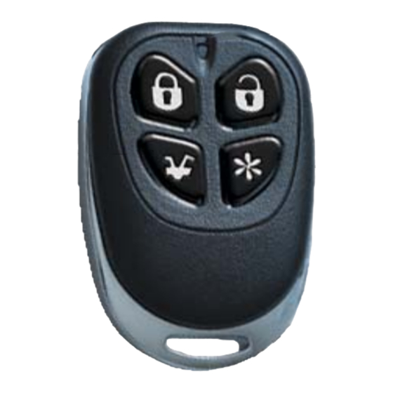
Remote Transmitters Remote Transmitter Description Button 1 Button 2 Button 3 Button 4 is a state-of-the-art remote starting system is supplied with two 4-button Remote G40RS Transmitters used to control system operations. The built-in remote start feature is designed to offer maximum convenience by remote starting your vehicle’s engine, turning on the heater/air conditioner, and then running for a pre-determined time to provide a comfortable environment once you enter your vehicle. - Page 4 Adding/Replacing Transmitters To replace lost or stolen transmitters or to add additional transmitters into the system, have all desired transmitters ready and follow the steps below. Note: Up to four transmitters can be programmed to operate the system. To erase any previously stored transmitter codes, be sure to program all 4 transmitter memory locations.
-
Page 5: System Operation
System Operation Remote Locking To Lock the doors: 1. Turn off the ignition. 2. Press Button 1. · The doors will lock. · The parking lights will flash once. · The LED will turn on, to indicate the doors are locked. 3. -
Page 6: Valet Mode
Valet Mode The Valet Mode temporarily disables the remote start system so the vehicle may be serviced by a mechanic. The remote transmitters will continue to lock/unlock the doors. To activate or deactivate the Valet Mode: 1. Turn on the ignition. 2. -
Page 7: Ignition Door Locking
Ignition Door Locking For added safety, the Ignition Door Locking feature allows vehicles equipped with power door lock systems to automatically lock the doors when the ignition is turned on. Ignition Door Unlocking For added convenience, this feature automatically unlocks the doors after the ignition key is turned off. The Ignition Door Unlocking feature may also be completely disabled if desired. -
Page 8: System Programming
System Programming Branch Feature Button 1 (default) Button 2 Button 3 1. Ignition Door Locking Enabled Disabled 2. Ignition Door Unlocking Enabled Disabled 3. Door Unlock Pulse Single Double 4. Door Lock Pulse Length 1 second 3 seconds 0.1 Sec 5. -
Page 9: System Installation
System Installation 8-Pin Main Harness Pin 1 RED WIRE: Module Power Input (+). Connect to a constant source of +12V Pin 2 GREEN/WHITE WIRE: Brake Input (+). Connect to the wire that shows +12V when pressing the brake. The Green/white wire is a safety shutdown wire that must be connected. Pin 3 BROWN/WHITE: Horn Output (-) 500 mA. -
Page 10: Starter Diagnostics
3-Pin White Door Lock Connector: Door lock port. 2-Pin Blue Connector: Valet switch port. Mount switch where it is accessible from the driver’s position. 2-Pin Red Connector: LED port. Mount LED where it may be easily seen from either side of the vehicle. 3-Pin White Door Lock Connector: Door lock port. - Page 11 Door Lock Diagrams Adding Actuators Negative Trigger Reverse Polarity Positive Trigger blue green Positive Horn Honk Page 10 - G 40RS...
-
Page 12: Wiring Diagram
Wiring Diagram Violet Starter Output Yellow Ignition 1 Output Orange Accessory Output Brown Ignition 2 Output +12V Battery Input #1 25 Amp. +12V Battery Input #2 25 Amp. +12V Battery Input #3 Green/White Brake Input(+) Control Unit Brown/White Horn Output (-)500mA White Parking Light 1 Output (+/- built-in relay) G-40RS...