Table of Contents
Advertisement
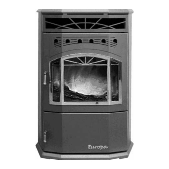
EUROPA 75
WARNING:
Improper installation, adjustment, alteration, service
or maintenance can cause injury, property damage,
or loss of life. Refer to this manual. For assistance or
additional information consult an authorized installer
or service agency.
FOR YOUR SAFETY:
Do not store or use gasoline or other fl ammable
vapours and liquids in the vicinity of this or any other
appliance.
Installation and service must be performed by an
authorized installer or service agency.
IMPORTANT: Save these Instructions.
Owners & Installation Manual
09/12/07
918-419e
FPI FIREPLACE PRODUCTS INTERNATIONAL, LTD. 6988 Venture St., Delta, BC, Canada V4G 1H4
Advertisement
Table of Contents

Related Manuals for FPI Dell-Point Europa 75

Summary of Contents for FPI Dell-Point Europa 75
- Page 1 Installation and service must be performed by an authorized installer or service agency. IMPORTANT: Save these Instructions. Owners & Installation Manual 09/12/07 918-419e FPI FIREPLACE PRODUCTS INTERNATIONAL, LTD. 6988 Venture St., Delta, BC, Canada V4G 1H4...
- Page 2 GF75-1 TO THE NEW OWNER Congratulations! You are the owner of a state-of-the-art stove by FPI. Thank-you for purchasing a FPI FIREPLACE PRODUCT. The pride of workmanship that goes into each of our products will give you years of trouble-free enjoyment.
-
Page 3: Table Of Contents
TABLE OF CONTENTS GREENFIRE BIOENERGY STOVE Safety Label ..............4 Operation Guidelines For Burning Corn And Wheat ...17 Initial Use of GF75-1 for Burning Corn & Wheat ..17 Starting Procedures .............17 INSTALLATION To Start Your Stove ..........17 Clinker Prevention ..........18 Important: Save These Instructions .......5 Before You Start ............5 MAINTENANCE Important Safety Information ........5... -
Page 4: Safety Label
The safety label is located on the back panel of the stove. NOTE: FPI units are constantly being improved. Check the label on the unit and if there is a difference, the label on the unit is the correct one. -
Page 5: Installation
We recommend that you call an accredited or any other parts of the stove. Use only professional or a dealer trained by FPI to guide 5. This appliance does not need outside air recommended products found at your local you to install your stove. -
Page 6: Chimney Installation
INSTALLATION the atmosphere directly to the 1" connector on HOW TO INSTALL THE BATTERY: CHIMNEY the back of the stove. (refer to Diagram 2 in INSTALLATION "Unit Dimensions" section). 1) Remove battery cage and battery from ash pan. Pressure Reducer Plate Important: Always use an approved 3”... -
Page 7: Clearances
INSTALLATION CLEARANCES See the safety label on the back of the stove to know the exact distances to follow when installing the stove. Corner Installation Alcove Installation Minimum Hearth Requirement BACK OF STOVE BACKWALL 3” 8 1/2” 6” (152mm) (152mm) 6”... -
Page 8: Vent Termination Requirements
4. If the unit is incorrectly vented or the air to fuel mixture is out of balance, a slight discoloration of the exterior of the house might occur. Since these factors are beyond the control of FPI we grant no guarantee against such incidents. -
Page 9: Horizontal Termination
INSTALLATION HORIZONTAL TERMINATION Top View Side View Diagram 4 GreenFire GF75-1 BioEnergy Stove... -
Page 10: Outside Vertical Termination
INSTALLATION OUTSIDE VERTICAL TERMINATION Side View Rain cap 24” (610mm) Flashing 3” (76 mm) Clearance Support bracket 6” Tee with cleanout Outside Air 6” Hearth Pad Diagram 5 GreenFire GF75-1 BioEnergy Stove... -
Page 11: Vertical Termination
INSTALLATION VERTICAL TERMINATION Optional Outside Air HIGHLY RECOMMENDED Top View 3” 2” 6” Type ‘L’ Vent 6” 6” Hearth Pad 6” Side View Rain cap 24” (610mm) Insulation must Flashing maintain 3” (76 mm) clearances Ceiling Support 3” (76 mm) Clearance Support bracket... -
Page 12: Existing Class "A" Chimney
INSTALLATION EXISTING CLASS "A" CHIMNEY Class A Chimney 3” to top of Class A Chimney Storm Collar Flashing Class A Chimney must maintain clearances outlined in the chimney’s installation instructions (usually 2”) Class A Chimney Ceiling Support 3” (76 mm) Clearance 3”... -
Page 13: Existing Masonry Chimney
INSTALLATION EXISTING MASONRY CHIMNEY Vertical Cap Cover Plate (non-combustible). Under edges of cover plate and Storm Collar storm collar must be sealed with silicone This flexible section of pipes must be no longer than 5ft, and must also be the first section nearest to the appliance, after the “T”... -
Page 14: Operating Instructions
OPERATING INSTRUCTIONS GF75-1 START UP PROCEDURE GF75-1 Start Up Procedures Icon/Display Description 1 & 2 Pre-set Combustion Blower COMB. at factory FLOW 3 & 4 Pre-set Ash-extraction at factory EXTR. A Display Settings 1 to 20 for icons 1-2-3-4 5 & 6 Heat level 1 to 5 HEAT LEVEL... -
Page 15: Quick Restart
OPERATING INSTRUCTIONS Quick Restart In case of a short power failure without battery back-up, there is a possibility of starting the unit only if fl ames are present in the burn pot. Caution: Never use gel or matches if the fl ame or the fuel bed contains red embers which are visible in the burner or the burner is hot. -
Page 16: Control Panel Functions
OPERATING INSTRUCTIONS CONTROL PANEL FUNCTIONS Combustion Fan Adjustment Use icon 1 to decrease or icon 2 to increase the pressure in the combustion chamber. These buttons are used to reduce or increase the amount of combustion air coming into the burn-pot. Display A This is a shared display between the Ash Extraction... -
Page 17: Operation Guidelines For Burning Corn And Wheat
OPERATING INSTRUCTIONS Initial Use Of GF75-1 For STARTING Please note that icon 10 (stop) will be the only functional key during the fi rst 30 Burning Corn & Wheat PROCEDURES minutes of the starting mode. All other keys are over-ridden in the process. When the In order to become better acquainted with this starting procedures are completed after the CAUTION: Do Not use the manual... -
Page 18: Clinker Prevention
OPERATING INSTRUCTIONS Clinker Prevention Low Fuel/ember Bed Control High Fuel/Ember Bed Control Clinkers are a result of incomplete combustion If under the above display conditions, you have If under above display conditions, you have in your burn-pot and, if by chance they occur, accumulated a high fuel/ember bed, the following accumulated a low fuel/ember bed the following can be controlled with correct use of your... -
Page 19: Maintenance
MAINTENANCE MAINTENANCE Maintenance Schedule Using Wood Pellets COMPONENTS OF STOVE EACH START UP WEEKLY MONTHLY ANNUALLY EMOVE ASHES IN HECK THE ASH REMOVAL SYSTEM MPTY THE ASH PAN ACUUM OUT THE COMBUSTION CHAMBER STEP LEAN THE BURN POT JETS LEAN THE CONVECTION PIPES SYSTEM HECK THE BATTERY CONDITIONS LEAN THE CONVECTION FAN FLYWHEEL... -
Page 20: Tools Required
MAINTENANCE Before each start-up, always check Maintenance Of The Burn-pot the level of ashes in the ash pan CONVECTION Step 1: Use a 9/16 wrench to unscrew the SYSTEM and remove if necessary. “Be sure to two nuts (Diagram 17). Then to raise the ring, dispose of in a metal container and it may be necessary to insert a fl... -
Page 21: Maintenance On The Convection Fan
MAINTENANCE Maintenance Of The Maintenance On The Combustion Maintenance On The Ash-extraction System Fan (Connected To The Chimney) Convection Fan Step 1: refer to Diagram 21 to determine There are two ways to clean the fan fl ywheel, To reach the convection fan, remove the control the condition of the three stainless steel ash either directly on the stove (Diagram 23) or panel (refer to diagram 25 &... -
Page 22: Inspection Of The Seals
28). If the gaskets need to be replaced use system including all lengths, T's and elbows. only approved gasket and adhesive obtainable from your FPI dealer. A proper high temperature gasket adhesive is also required. Maintenance Of The Battery System Check that the grips are well connected on the battery poles. -
Page 23: Gf75-1 Technical Data
26.5" (673 mm) Depth 25.25" (641 mm) Weight Approximately 305 lb (138 kg) Type of Chimney FPI recommends the use of corn venting for all applications. Diameter of the Chimney 3" (76 mm) of interior diameter GreenFire GF75-1 BioEnergy Stove... -
Page 24: Troubleshooting
TROUBLESHOOTING TROUBLESHOOTING IMPORTANT: Always disconnect your stove before doing any maintenance or repairs. Only a qualifi ed technician should take care of any electrical problems. Error code Problem Solution Shows when stove is connected If desired, start stove. but shut down. a) Poor start-up. -
Page 25: Electrical Diagram (12 Volts)
TROUBLESHOOTING ELECTRICAL DIAGRAM (12 VOLTS) Pin 1 & 2 = purple wires (not used) Pin 13 = red wire (combustion fan) Power supply Pin 3 & 4 = orange wires (safety) Pin 14 = black wire (convection fan) converts the Pin 5 &... - Page 26 NOTES ___________________________________________________ ___________________________________________________ ___________________________________________________ ___________________________________________________ ___________________________________________________ ___________________________________________________ ___________________________________________________ ___________________________________________________ ___________________________________________________ ___________________________________________________ ___________________________________________________ ___________________________________________________ ___________________________________________________ ___________________________________________________ ___________________________________________________ ___________________________________________________ ___________________________________________________ ___________________________________________________ ___________________________________________________ ___________________________________________________ ___________________________________________________ ___________________________________________________ ___________________________________________________ ___________________________________________________ GreenFire GF75-1 BioEnergy Stove...
-
Page 27: Warranty
The warranty will commence on the purchase date of the appliance. Any part or parts of this unit which in our judgement show evidence of such defects will be repaired or replaced at FPI’s option through an authorized distributor or agent provided that the replaced part is returned to FPI via the distributor or agent Transportation Prepaid. - Page 28 Printed in Canada © Copyright 2007, FPI Fireplace Products International Ltd. All rights reserved.