
Related Manuals for Cub Cadet Commercial 25HP Tank 53AB5BAX150


Summary of Contents for Cub Cadet Commercial 25HP Tank 53AB5BAX150
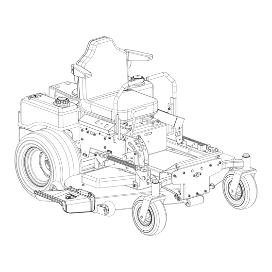
- Page 1 Hydrostatic Zero-Turn Commercial Riding Mower Professional Turf Equipment MODEL 25HP Tank 53AB5BAX150 53AB5DCX150 OPERATOR’S AND SERVICE MANUAL...
-
Page 2: Table Of Contents
TABLE OF CONTENTS Foreword............. . . 3 General Safety Operations . -
Page 3: Foreword
FORWARD The 25HP Tank Hydrostatic Zero-Turn Commercial Riding Mower provides superb maneuver- ability, mid-mount cutting capability for professional landscapers, commercial lawn service companies, professional turf managers and golf course superintendents. The machine incor- porates many safety features that should be studied by all operators and maintenance person- nel before use. -
Page 4: General Safety Operations
GENERAL SAFETY 6. Do not check for hydraulic leaks with any part of the body. OPERATIONS 7. Do not add fuel to a machine when the engine is running and/or the exhaust system is hot. A. DANGER 8. Keep machine clean and free of debris, grass, Do not operate machine in confined areas leaves, oil, grease, etc. -
Page 5: Related To Fuel
11. When looking for oil leaks, never run your movements of the levers when starting or hand over hydraulic hoses, lines or fittings. stopping. Never tighten or adjust hydraulic hoses, lines 3. If the mower is equipped for side discharge, or fittings while the system is under pressure. -
Page 6: Safety Decals
SAFETY DECALS AND LABELS WARNING SHIELD MISSING DO NOT OPERATE Part Number: 00030635 Part Number: 01003858 DANGER ROTATING BLADE Do not put hands or feet under or into mower when engine is running. Part Number: 01003449 Part Number: 00030633 Part Number: 01003450 Part Number: 01003859 Part Number: 01002166 T O R E D U C E T H E R I S K O F I N J U R Y,... -
Page 7: Specifications
SPECIFICATIONS Engine: 25HP Kohler, 25HP Kawasaki Type: Vertical air cooled V-Twin Air Cleaner: Paper Element Lube System: Pressurized with oil filter Starter: 12-volt electric Traction Drive: Engine to two variable-speed hydraulic pump motor to gearbox on each drive wheel Hydraulic Tank: 10 quart capacity, One quart filter Cutter Deck;Drive: 60"... -
Page 8: Operating Instructions
OPERATING INSTRUCTIONS Figure. 1 Figure. 2 Tach and Electric Blade Engine throttle Hour Meter Clutch Switch Choke Lever Ignition Switch A.General ing and raise the cutting deck to the trans- port position. Always allow other vehicles 1. When Mowing: to have the right of way. a. -
Page 9: Controls
c. Avoid turning when going downhill, traction B.Controls is at a minimum going downhill. 1. Engine Ignition and Start Switch: (See Fig- d. Do not operate with discharge side of the ure 1.) Located on the instrument housing mower toward streets, buildings, play- below the right side of the operator’s seat. - Page 10 Steering Levers Deck Lift Handle Brake Figure. 4 Fuel Shutoff Valve Figure. 3 pedal assembly. Fold the pedal up to vertical 4. Electric Blade Clutch Switch: (See Figure position so the hole in the pedal aligns with 1.) Located on the right side of the mower the hole in the lever.
-
Page 11: Initial Adjustments
C.Initial Adjustments the procedures below to set the appropriate angle to the mowing deck. 1. Check the fluid levels and tires: a. Park the mower on a flat paved surface, Note: engage the parking brake, shut off the These checks should be made daily, engine, remove the key from the ignition before starting the engine. -
Page 12: Zero Turn Break-In And Operating Procedures
clockwise a few turns. Adjust both front d. Inspect the machine to make sure: and rear Deck links as necessary. 1. All guards, shields (including mower Retighten nuts. chute deflector) are in their proper place, Raise the mowing deck to the transport are secure, and are functional. - Page 13 run. Turn off the PTO by pushing the The more the lap bars are moved toward control switch down. the rear of the machine, the faster the h. To drive in the FORWARD direction: machine will move in the reverse direc- 1.
-
Page 14: Maintenance And Service
e. Push the throttle control to a position a levers backward the faster the mower will third of the way between slow and fast. go backward. Insert the key in the ignition and start To turn, pull the lever back on the side to switch and turn the switch to “On”. - Page 15 Linch Pins Linch Pins Figure. 6 Height of Cut Clevis Pin d. Detach the mower drive belt. a. Set the parking brake. b. Clean any debris from the blades. Keep e. Remove six linchpins (See Fig. 6) (4) from blades sharp and free of build up at all the deck and (2) from the front of the times.
-
Page 16: Hydraulic Oil
Cover Plate Spindle Figure. 8 Hydraulic Tank 1. Adding Hydraulic Oil (use SAE20W 50) a. Place the Mower on a level surface and engage the parking brake. Figure. 7 b. Stop the engine and remove the key from the ignition switch. e. -
Page 17: Electrical System
caps and drain oil from both left and right c. Store the battery with a full charge. A dis- pumps. Replace and retighten nuts. charged battery will freeze (refer to the table below). Hydraulic pumps Specific Gravity Freezing Temp (°F) 1.265 1.250 1.200... - Page 18 other electrical components. This is a stan- steering lever up to the operating position dard plug-in type automotive fuse rated at 7.5 and try to start the engine. The engine amp. should not start. If it does, the left steering Safety Switches: There are five safety lever switch must be repositioned or per- switches in the electrical circuit which control...
-
Page 19: Tires
the wiring harness and the connections to the other side of the caster yoke. Then tighten the locknut on the end of the axle the seat switch, the blade clutch switch and assembly. the electric blade clutch. Then check out the seat switch, the blade clutch switch and Lower the mower off the jack and continue finally the electric blade clutch. -
Page 20: Hydraulic System
Note: damaged hoses. Make certain there are no To move the mower forward or in kinks or twists in any hose. reverse by pushing, you must release the Hydraulic Oil Tank and Filter: dynamic braking. Locate the valves on the pump. -
Page 21: G.storage
Note: The pumps are not owner-repairable. in temperature. Before storing, the following If a pump fails, contact your Cub Cadet Com- maintenance procedures should be per- mercial dealer. Do not disassemble the pump. formed. -
Page 22: Maintenance Schedule
Inspect the hydraulic hoses, lines and fit- Clean or replace the engine’s paper air tings. Replace as necessary. cleaner element.* Jack the mower up and store it on blocks to Check the battery’s electrolyte level. take the weight off of the tires. Clean the engine cooling fins and external 2. -
Page 23: Lubrication Chart
OIL CHART Apply a few drops of SAE 20W-50 engine oil or use a spray lubricant. Apply the oil to both sides of pivot points. Wipe off any excess. Start engine and operate mower briefly to insure that oil spreads evenly. Number of Oil Points Description DAILY... -
Page 24: Performance Adjustments
Performance Adjustments B. Enginge RPM Check and Adjustment Description High RPM Spec. Low RPM Spec. A. High Speed Tracking Adjustment 25 HP Kawasaki 3600 +/-50 1550 +/-100 If mower tracks to one side with both lap bars in fully 25 HP Kohler 3600 +/-50 1550 +/-100 forward position:... -
Page 25: Deck Corner Ball Wheel Roller Settings
g. Verify proper throttle adjustment by check- b. The seat has five inches of front-to-rear ing RPM readings as outlined above. adjustment available. Check factory settings of lap bars for the con- C. Deck Corner Ball Wheel Roller Settings ditions listed above. Note: Matching the set heights of the ball rollers on If lap bar adjustments are required,... -
Page 26: F Deck Leveling Procedure
F. Deck leveling Procedure aligned along the mower centerline. The blade- to-ground height at the rear of the blade tip Park the mower on a flat paved surface, engage should be 1/8" to 1/4” higher than the front tip. the parking brake, shut off the engine, remove This is referred to as blade pitch. -
Page 27: Wiring Diagram
WIRING DIAGRAM... -
Page 28: Maintenance Record
MAINTENANCE RECORD DATE WORK PERFORMED DATE WORK PERFORMED... - Page 29 MAINTENANCE RECORD DATE WORK PERFORMED DATE WORK PERFORMED...
- Page 30 MAINTENANCE RECORD DATE WORK PERFORMED DATE WORK PERFORMED...
- Page 31 MAINTENANCE RECORD DATE WORK PERFORMED DATE WORK PERFORMED...
- Page 32 Cadet Commercial dealer subject to the above time and coverage limitations. Upon completion of your purchase, the Serial Number/s of the unit will be registered with the Cub Cadet. This will initiate and validate your limited warranty and the applicable Warranty Period.