Advertisement
Quick Links
Instruction
Manual
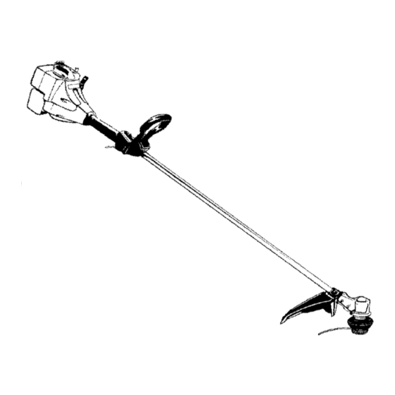
25cc/1.5 cu.in. 2-Cycle
17 Inch Cutting Path / 0.080 Inch Line
GASOLINE
WEEDWAOKER
®
Model
No.
358.795571
•
Safety
•
Assembly
•
Operation
•
Maintenance
•
Parts List
•
Espar_ol
For Occasional
Use Only
£U U
WARNING:
Read and follow all Safety
Rules and Operating
Instructions
before first use of this product.
For answers
to your questions
about this product:
Call 7 am-7
pm, Mon.-Sat.,
or 10 am-7
pm, Sun.
1-800-235-5878
(Hours listed are Central
Time)
Sears, Roebuck
and Co., Hoffman
Estates,
IL 60179 U.S.A.
530163856
4/23/03
Advertisement

Related Manuals for Craftsman WEEDWACKER 358.795571


Summary of Contents for Craftsman WEEDWACKER 358.795571
- Page 1 Instruction Manual 25cc/1.5 cu.in. 2-Cycle 17 Inch Cutting Path / 0.080 Inch Line GASOLINE WEEDWAOKER ® Model 358.795571 • Safety • Assembly • Operation • Maintenance • Parts List • Espar_ol For Occasional Use Only £U U WARNING: Read and follow all Safety Rules and Operating Instructions before first use of this product.
- Page 2 Parts and Ordering Back FULL ONE YEAR WARRANTY ON CRAFTSMAN ® GAS POWERED WEEDWACKER ® LINE TRIMMER For one year from the date of purchase, when this Craftsman Gas Powered Weedwacker Line Trimmer is maintained, lubricated, and tuned up according the operating...
- Page 3 • Use only for jobs explained in this • Use only 0.080 inch (2 mm) diame- manual. ter Craftsman@ brand line. Never TRANSPORTING AND STORAGE use wire, rope, string, etc. • Install required shield properly be- •...
- Page 4 • Store u nit a nd fuel i narea where ers who operate power tools o nacon- fuel vapors cannot reach s parks or tinual and regular basis m ust monitor open f lames from water heaters, closely their p hysical condition and the condition ofthis tool.
- Page 5 For p roper orientation ofshield, see KNOW YOUR TRIMMER illustration inOP- Bracket ERATION section. Slot 1. Remove wing n ut f rom shield. Wing Nut 2. Insert bracket into slot asshown. 3. Pivot shield u ntil bolt p asses through hole inbracket. 4.
- Page 6 We recommend Craftsman brand Slowly press the primer bulb 6 synthetic oil. M ix gasoline and oilata times. ratio of40:1. A40:1 ratio isobtained Move the start lever to the START bymixing 3.2 ounces ofoil w ith 1 position. gallon o funleaded gasoline. Included with this trimmer isa3.2 ounce...
- Page 7 could r equire pulling the starter handle many t imes, depending onhow badly the unit i sflooded. Ifthe unit s till d oesn't start, refer tothe TROUBLESHOOTING TABLE orcall 1-800-235-5878. OPERATING INSTRUCTIONS TRIMMER LINE ADVANCE OPERATING POSITION The cutting head advances line au- ALWAYS WEAR: _ tomatically.
- Page 8 • For t rimming orscalping, use less than full t hrottle toincrease line life Mowing and decrease head wear, especially: • During light duty cutting. • Near objects around which the line can wrap such as small posts, trees or fence wire. •...
- Page 9 MAINTENANCE SCHEDULE WARNING: Disconnect the spark plug before performing maintenance except for carburetor adjustments. CARE & MAINTENANCE TASK WHEN TO PERFORM Before each use Check for loose fasteners and parts Before each use Check for damaged or worn parts After each use Inspect and clean unit and labels Clean air filter Every 5 hours of operation...
- Page 10 • Engine will not idle when the throttle is released. 1. Cut a length of 25 feet of 0.080 inch (2 mm) diameter round Craftsman Make adjustments with the unit sup- brand line. ported so the cutting attachment...
- Page 11 Run engine at least 5 min- reach sparks or open flames from utes after adding stabilizer. water heaters, electric motors or Craftsman 40:1,2-cycle engine oil (air switches, furnaces, etc. cooled) is already blended with fuel •...
- Page 12 TROUBLESHOOTING TABLE WARNING: Always stop unit and disconnect spark plug before perform- ing all of the recommended remedies below except remedies that require operation of the unit. REMEDY TROUBLE CAUSE 1. Move ON/OFF switch to ON. Engine will not 1. Engine ON/OFF switch start.
- Page 13 orworkmanship ofthe engine causes uled only for regular inspection to the the failure ofsuch anemission related effect of "repair or replace as neces- part, the part will b erepaired orre- sary" shall be warranted for 2 years, placed bySears. OWNER'S WAR- Any warranted part which is scheduled RANTY RESPONSIBILITIES:...