Table of Contents
Troubleshooting

Related Manuals for Gigabyte GA-MA78LM-S2


Summary of Contents for Gigabyte GA-MA78LM-S2
- Page 1 GA-MA78LM-S2H/ GA-MA78LM-S2 AM2+/AM2 socket motherboard for AMD Phenom II processor/ AMD Phenom processor/ ™ ™ AMD Athlon II processor/ AMD Athlon processor/ ™ ™ AMD Sempron processor ™ User's Manual Rev. 1001 12ME-MA78L2H-1001R...
-
Page 3: Identifying Your Motherboard Revision
GIGABYTE's prior written permission. Documentation Classifications In order to assist in the use of this product, GIGABYTE provides the following types of documentations: For detailed product information, carefully read the User's Manual. -
Page 4: Table Of Contents
Table of Contents Box Contents ........................6 Optional Items .........................6 GA-MA78LM-S2H/GA-MA78LM-S2 Motherboard Layout ..........7 Block Diagram .........................8 Chapter 1 Hardware Installation ..................9 Installation Precautions ..................9 1-2 Product Specifications ..................10 Installing the CPU and CPU Cooler ............... 13 1-3-1 Installing the CPU ....................13 1-3-2 Installing the CPU Cooler ..................15... - Page 5 Chapter 3 Drivers Installation ..................55 Installing Chipset Drivers ................55 Application Software ..................56 Technical Manuals ..................56 Contact ......................57 System ......................57 Download Center ................... 58 Chapter 4 Unique Features ...................59 Xpress Recovery2 ..................59 BIOS Update Utilities ..................62 4-2-1 Updating the BIOS with the Q-Flash Utility .............62 4-2-2...
-
Page 6: Box Contents
Box Contents GA-MA78LM-S2H or GA-MA78LM-S2 motherboard Motherboard driver disk User's Manual One IDE cable Two SATA 3Gb/s cables I/O Shield • The box contents above are for reference only and the actual items shall depend on the product package you obtain. -
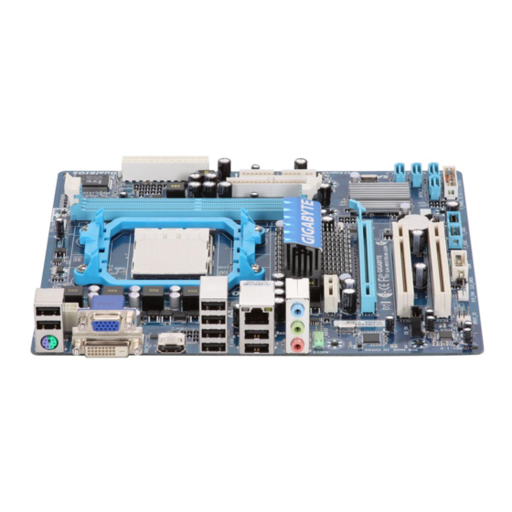
Page 7: Ga-Ma78Lm-S2H/Ga-Ma78Lm-S2 Motherboard Layout
GA-MA78LM-S2H/GA-MA78LM-S2 Motherboard Layout (Note) _USB M_BIOS CPU_FAN ATX_12V B_BIOS Socket AM2 AUDIO F_AUDIO PCIEX1 AMD 760G PCIEX16 RTL8111D GA-MA78LM-S2H/GA-MA78LM-S2 AMD SB710 PCI1 CD_IN SATA2_3 SATA2_2 PCI2 SATA2_0 CODEC SATA2_1 F_PANEL CLR_CMOS F_USB2 F_USB1 SPDIF_IO SYS_FAN Only for GA-MA78LM-S2H (Note) Use this port to connect a PS/2 keyboard or PS/2 mouse. -
Page 8: Block Diagram
Block Diagram CPU CLK+/- (200 MHz) AM3/AM2+/AM2 PCIe CLK DDR2 1200(O.C.)1066/800 MHz (100 MHz) Dual Channel Memory 1 PCI Express x16 Hyper Transport Bus GFX CLK (100 MHz) PCI Express x16 AMD 760G D-Sub PCI Express Bus (Note) DVI-D or HDMI j RTL8111D PCIe CLK (100 MHz) -
Page 9: Chapter 1 Hardware Installation
Chapter 1 Hardware Installation Installation Precautions The motherboard contains numerous delicate electronic circuits and components which can become damaged as a result of electrostatic discharge (ESD). Prior to installation, carefully read the user's manual and follow these procedures: • Prior to installation, do not remove or break motherboard S/N (Serial Number) sticker or warranty sticker provided by your dealer. -
Page 10: Product Specifications
II processor/ AMD Athlon processor/ ™ ™ AMD Sempron processor ™ (Go to GIGABYTE's website for the latest CPU support list.) Hyper Transport Bus 5200/2000 MT/s Chipset North Bridge: AMD 760G South Bridge: AMD SB710 Memory 2 x 1.8V DDR2 DIMM sockets supporting up to 8 GB of system memory (Note 1) ... - Page 11 Internal 1 x 24-pin ATX main power connector Connectors 1 x 4-pin ATX 12V power connector 1 x floppy disk drive connector 1 x IDE connector 4 x SATA 3Gb/s connectors 1 x CPU fan header 1 x system fan header ...
- Page 12 Unique Features Support for @BIOS Support for Q-Flash Support for Xpress BIOS Rescue Support for Download Center Support for Xpress Install Support for Xpress Recovery2 Support for EasyTune (Note 6) Bundled Software Norton Internet Security (OEM version) Operating System ...
-
Page 13: Installing The Cpu And Cpu Cooler
Read the following guidelines before you begin to install the CPU: • Make sure that the motherboard supports the CPU. (Go to GIGABYTE's website for the latest CPU support list.) • Always turn off the computer and unplug the power cord from the power outlet before installing the CPU to prevent hardware damage. - Page 14 B. Follow the steps below to correctly install the CPU into the motherboard CPU socket. • Before installing the CPU, make sure to turn off the computer and unplug the power cord from the power outlet to prevent damage to the CPU. • Do not force the CPU into the CPU socket. The CPU cannot fit in if oriented incorrectly. Adjust the CPU orientation if this occurs.
-
Page 15: Installing The Cpu Cooler
1-3-2 Installing the CPU Cooler Follow the steps below to correctly install the CPU cooler on the CPU. (The following procedure uses the GIGABYTE cooler as the example.) Step 1: Step 2: Place the CPU cooler on the CPU. Apply an even and thin layer of thermal grease on the surface of the installed CPU. -
Page 16: Installing The Memory
• Make sure that the motherboard supports the memory. It is recommended that memory of the same capacity, brand, speed, and chips be used. (Go to GIGABYTE's website for the latest memory support list.) • Always turn off the computer and unplug the power cord from the power outlet before installing the memory to prevent hardware damage. -
Page 17: Installing A Memory
1-4-2 Installing a Memory Before installing a memory module , make sure to turn off the computer and unplug the power cord from the power outlet to prevent damage to the memory module. DDR2 DIMMs are not compatible to DDR DIMMs. Be sure to install DDR2 DIMMs on this moth- erboard. -
Page 18: Installing An Expansion Card
Installing an Expansion Card Read the following guidelines before you begin to install an expansion card: • Make sure the motherboard supports the expansion card. Carefully read the manual that came with your expansion card. • Always turn off the computer and unplug the power cord from the power outlet before installing an expansion card to prevent hardware damage. -
Page 19: Back Panel Connectors
Back Panel Connectors (Note 1) (Note 2) (Note 2) USB Port The USB port supports the USB 2.0/1.1 specification. Use this port for USB devices such as a USB key- board/mouse, USB printer, USB flash drive and etc. PS/2 Keyboard/Mouse Port Use this port to connect a PS/2 keyboard or mouse. D-Sub Port The D-Sub port supports a 15-pin D-Sub connector. Connect a monitor that supports D-Sub connection to this port. - Page 20 A. Dual Display Configurations: This motherboard provides three ports for video output: DVI-D, HDMI and D-Sub. The table below shows the supported dual display configurations. Dual Combination Supported or Not DVI-D + D-Sub Display DVI-D + HDMI HDMI + D-Sub B. Playback of HD DVD and Blu-ray Discs: In order to get better playback quality, when playing the HD DVD or Blu-ray discs, refer to the recom mended system requirements (or better) below.
-
Page 21: Internal Connectors
Internal Connectors ATX_12V F_AUDIO CD_IN CPU_FAN SPDIF_IO SYS_FAN F_USB1/F_USB2 CLR_CMOS SATA2_0/1/2/3 F_PANEL Read the following guidelines before connecting external devices: • First make sure your devices are compliant with the connectors you wish to connect. • Before installing the devices, be sure to turn off the devices and your computer. Unplug the power cord from the power outlet to prevent damage to the devices. - Page 22 1/2) ATX_12V/ATX (2x2 12V Power Connector and 2x12 Main Power Connector) With the use of the power connector, the power supply can supply enough stable power to all the components on the motherboard. Before connecting the power connector, first make sure the power supply is turned off and all devices are properly installed.
-
Page 23: Fdd (Floppy Disk Drive Connector)
3/4) CPU_FAN/SYS_FAN (Fan Headers) The motherboard has a 4-pin CPU fan header (CPU_FAN) and a 3-pin (SYS_FAN) system fan headers. Most fan headers possess a foolproof insertion design. When connecting a fan cable, be sure to connect it in the correct orientation (the black connector wire is the ground wire). The motherboard supports CPU fan speed control, which requires the use of a CPU fan with fan speed control design. - Page 24 6) IDE (IDE Connector) The IDE connector supports up to two IDE devices such as hard drives and optical drives. Before attach- ing the IDE cable, locate the foolproof groove on the connector. If you wish to connect two IDE devices, remember to set the jumpers and the cabling according to the role of the IDE devices (for example, master or slave). (For information about configuring master/slave settings for the IDE devices, read the instructions from the device manufacturers.)
-
Page 25: F_Panel Front Panel Header
8) F_PANEL (Front Panel Header) Connect the power switch, reset switch, speaker, chassis intrusion switch/sensor and system status indicator on the chassis to this header according to the pin assignments below. Note the positive and negative pins before connecting the cables. Message/Power/ Power Speaker... -
Page 26: Cd In Connector
9) F_AUDIO (Front Panel Audio Header) The front panel audio header supports Intel High Definition audio (HD) and AC'97 audio. You may connect your chassis front panel audio module to this header. Make sure the wire assignments of the module con- nector match the pin assignments of the motherboard header. Incorrect connection between the module connector and the motherboard header will make the device unable to work or even damage it. For HD Front Panel Audio: For AC'97 Front Panel Audio: Pin No. Definition... - Page 27 11) SPDIF_IO (S/PDIF In/Out Header) This header supports digital S/PDIF In/Out. Via an optional S/PDIF In and Out cable, this header can connect to an audio device that supports digital audio out and an audio system that supports digital au- dio in.
-
Page 28: Clearing Cmos Jumper
13) COM (Serial Port Header) The COM header can provide one serial port via an optional COM port cable. For purchasing the op- tional COM port cable, please contact the local dealer. Pin No. Definition NDCD- NSIN NSOUT NDTR- NDSR- NRTS- NCTS- NRI- No Pin... - Page 29 15) BAT The battery provides power to keep the values (such as BIOS configurations, date, and time information) in the CMOS when the computer is turned off. Replace the battery when the battery voltage drops to a low level, or the CMOS values may not be accurate or may be lost. You may clear the CMOS values by removing the battery: 1.
- Page 30 Hardware Installation - 30 -...
-
Page 31: Chapter 2 Bios Setup
To see more advanced BIOS Setup menu options, you can press <Ctrl> + <F1> in the main menu of the BIOS Setup program. To upgrade the BIOS, use either the GIGABYTE Q-Flash or @BIOS utility. Q-Flash allows the user to quickly and easily upgrade or back up BIOS without entering the operating •... -
Page 32: Startup Screen
Startup Screen The following screens may appear when the computer boots. Award Modular BIOS v6.00PG, An Energy Star Ally Copyright (C) 1984-2009, Award Software, Inc. GA-MA78LM-S2H F1b Motherboard Model BIOS Version Function Keys <DEL>: BIOS Setup <F9>: XpressRecovery2 <F12>: Boot Menu <End>: Qflash 08/10/2009-RS780-SB710-7A66AG0NC-00 Function Keys: <DEL>: BIOS SETUP... -
Page 33: The Main Menu
The Main Menu Once you enter the BIOS Setup program, the Main Menu (as shown below) appears on the screen. Use ar- row keys to move among the items and press <Enter> to accept or enter a sub-menu. (Sample BIOS Version: GA-MA78LM-S2H F1b) CMOS Setup Utility-Copyright (C) 1984-2009 Award Software MB Intelligent Tweaker(M.I.T.) Load Fail-Safe Defaults... -
Page 34: Advanced Bios Features
The Functions of the <F11> and <F12> keys (For the Main Menu Only) F11: Save CMOS to BIOS This function allows you to save the current BIOS settings to a profile. You can create up to 8 profiles (Profile 1-8) and name each profile. First enter the profile name (to erase the default profile name, use the SPACE key) and then press <Enter> to complete. F12: Load CMOS from BIOS If your system becomes unstable and you have loaded the BIOS default settings, you can use this function to load the BIOS settings from a profile created before, without the hassles of reconfiguring the BIOS settings. First select the profile you wish to load, then press <Enter> to complete. -
Page 35: Mb Intelligent Tweaker(M.i.t.)
MB Intelligent Tweaker(M.I.T.) MB Intelligent Tweaker(M.I.T.) CMOS Setup Utility-Copyright (C) 1984-2009 Award Software MB Intelligent Tweaker(M.I.T.) Item Help Advanced Clock Calibration [Press Enter] Menu Level CPU Clock Ratio [Auto] CPU NorthBridge Freq. [Auto] (Note) CPU Host Clock Control [Auto] x CPU Frequency(MHz) PCIE Clock(MHz) - Page 36 Advanced Clock Calibration CMOS Setup Utility-Copyright (C) 1984-2009 Award Software Advanced Clock Calibration Item Help EC Firmware Selection [Normal] Menu Level Advanced Clock Calibration [Disabled] x Value (All Cores) x Value (Core 0) x Value (Core 1) x Value (Core 2) x Value (Core 3) hi...
-
Page 37: Memory Clock
CPU Clock Ratio Allows you to alter the clock ratio for the installed CPU. The adjustable range is dependent on the CPU being used. CPU NorthBridge Freq. (Note) Allows you to alter the North Bridge controller frequency for the installed CPU. The adjustable range is dependent on the CPU being used. - Page 38 When you use an AM2 CPU: DDR 400 Sets Memory Clock to DDR 400. DDR 533 Sets Memory Clock to DDR 533. DDR 667 Sets Memory Clock to DDR 667. DDR 800 Sets Memory Clock to DDR 800. ******** System Voltage Optimized ******** System Voltage Control Determines whether to manually set the system voltages.
-
Page 39: Standard Cmos Features
Standard CMOS Features CMOS Setup Utility-Copyright (C) 1984-2009 Award Software Standard CMOS Features Item Help Date (mm:dd:yy) Wed, Jun 3 2009 Menu Level Time (hh:mm:ss) 22:31:24 IDE Channel 0 Master [None] IDE Channel 0 Slave [None] IDE Channel 1 Master [None] ... - Page 40 The following fields display your hard drive specifications. If you wish to enter the parameters manually, refer to the information on the hard drive. Capacity Approximate capacity of the currently installed hard drive. Cylinder Number of cylinders. Head Number of heads. Precomp Write precompensation cylinder. Landing Zone Landing zone. Sector Number of sectors. Drive A Allows you to select the type of floppy disk drive installed in your system. If you do not install a floppy disk drive, set this item to None.
-
Page 41: Advanced Bios Features
Advanced BIOS Features CMOS Setup Utility-Copyright (C) 1984-2009 Award Software Advanced BIOS Features Item Help Internal Graphics Mode [UMA] Menu Level UMA Frame Buffer Size [Auto] x Surround View Disabled Onboard VGA output connectj [D-SUB/DVI] AMD C1E Support [Disabled] (Note) Virtualization [Disabled]... -
Page 42: Hard Disk Boot Priority
Patch AMD TLB Erratum (Note) Enables or disables the Patch AMD TLB Erratum function. (Default: Enabled) AMD K8 Cool&Quiet control Auto Lets the AMD Cool'n'Quiet driver dynamically adjust the CPU clock and VID to reduce heat output from your computer and its power consumption. (Default) Disabled Disables this function. -
Page 43: Integrated Peripherals
Integrated Peripherals CMOS Setup Utility-Copyright (C) 1984-2009 Award Software Integrated Peripherals Item Help OnChip IDE Channel [Enabled] Menu Level OnChip SATA Controller [Enabled] OnChip SATA Type [Native IDE] Onboard LAN Function [Enabled] Onboard LAN Boot ROM [Disabled] SMART LAN [Press Enter] Onboard Audio Function [Enabled]... - Page 44 SMART LAN (LAN Cable Diagnostic Function) CMOS Setup Utility-Copyright (C) 1984-2009 Award Software SMART LAN Item Help Start detecting at Port..Menu Level Part1-2 Status = Open / Length = Part3-6 Status = Open / Length = Part4-5 Status = Open / Length = Part7-8 Status = Open / Length = hi...
-
Page 45: Usb Keyboard Support
Onboard Audio Function Enables or disables the onboard audio function. (Default: Enabled) If you wish to install a 3rd party add-in audio card instead of using the onboard audio, set this item to Disabled. OnChip USB Controller Enables or disables the integrated USB 1.1 controller. (Default: Enabled) Disabled will turn off all of the USB functionalities below. -
Page 46: Power Management Setup
Power Management Setup CMOS Setup Utility-Copyright (C) 1984-2009 Award Software Power Management Setup Item Help ACPI Suspend Type [S3(STR)] Menu Level Soft-Off by Power button [Instant-off] USB Wake Up from S3 [Enabled] Modem Ring Resume [Disabled] PME Event Wake Up [Enabled] HPET Support [Enabled]... - Page 47 PME Event Wake Up Allows the system to be awakened from an ACPI sleep state by a wake-up signal from a PCI or PCIe de- vice. Note: To use this function, you need an ATX power supply providing at least 1A on the +5VSB lead. (Default: Enabled) HPET Support (Note)
-
Page 48: Pnp/Pci Configurations
PnP/PCI Configurations CMOS Setup Utility-Copyright (C) 1984-2009 Award Software PnP/PCI Configurations Item Help PCI1 IRQ Assignment [Auto] Menu Level PCI2 IRQ Assignment [Auto] hi : Move Enter: Select +/-/PU/PD: Value F10: Save ESC: Exit F1: General Help F5: Previous Values F6: Fail-Safe Defaults F7: Optimized Defaults PCI1 IRQ Assignment... -
Page 49: Pc Health Status
PC Health Status CMOS Setup Utility-Copyright (C) 1984-2009 Award Software PC Health Status Item Help Hardware Thermal Control [Enabled] Menu Level Reset Case Open Status [Disabled] Case Opened Vcore 1.376V DDR2 1.8V 1.872V +3.3V 3.328V +12V 12.112V Current System Temperature Current CPU Temperature Current CPU FAN Speed 3375 RPM... - Page 50 CPU/SYSTEM FAN Fail Warning Allows the system to emit warning sound if the CPU/system fan is not connected or fails. Check the fan condition or fan connection when this occurs. (Default: Disabled) CPU Smart FAN Control Enables or disables the CPU fan speed control function. Enabled allows the CPU fan to run at different speed according to the CPU temperature.
-
Page 51: Load Fail-Safe Defaults
2-10 Load Fail-Safe Defaults CMOS Setup Utility-Copyright (C) 1984-2009 Award Software MB Intelligent Tweaker(M.I.T.) Load Fail-Safe Defaults Standard CMOS Features Load Optimized Defaults Advanced BIOS Features Set Supervisor Password Integrated Peripherals Set User Password Power Management Setup Save &... -
Page 52: Set Supervisor/User Password
2-12 Set Supervisor/User Password CMOS Setup Utility-Copyright (C) 1984-2009 Award Software MB Intelligent Tweaker(M.I.T.) Load Fail-Safe Defaults Standard CMOS Features Load Optimized Defaults Advanced BIOS Features Set Supervisor Password Integrated Peripherals Set User Password Power Management Setup Save &... -
Page 53: Save & Exit Setup
2-13 Save & Exit Setup CMOS Setup Utility-Copyright (C) 1984-2009 Award Software MB Intelligent Tweaker(M.I.T.) Load Fail-Safe Defaults Standard CMOS Features Load Optimized Defaults Advanced BIOS Features Set Supervisor Password Save to CMOS and EXIT (Y/N)? Y Integrated Peripherals Set User Password ... - Page 54 BIOS Setup - 54 -...
-
Page 55: Chapter 3 Drivers Installation
Chapter 3 Drivers Installation • Before installing the drivers, first install the operating system. • After installing the operating system, insert the motherboard driver disk into your optical drive. The driver Autorun screen is automatically displayed which looks like that shown in the screen shot below. (If the driver Autorun screen does not appear automatically, go to My Computer, double-click the optical drive and execute the Run.exe program.) Installing Chipset Drivers After inserting the driver disk, "Xpress Install"... -
Page 56: Application Software
Application Software This page displays all the utilities and applications that GIGABYTE develops and some free software. You can click the Install button on the right of an item to install it. Technical Manuals This page provides GIGABYTE's application guides, content descriptions for this driver disk, and the mother- board manuals. -
Page 57: Contact
Contact For the detailed contact information of the GIGABYTE Taiwan headquarter or worldwide branch offices, click the URL on this page to link to the GIGABYTE website. System This page provides the basic system information. - 57 - Drivers Installation... -
Page 58: Download Center
Download Center To update the BIOS, drivers, or applications, click the Download Center button to link to the GIGABYTE website. The latest version of the BIOS, drivers, or applications will be displayed. Drivers Installation - 58 -... -
Page 59: Chapter 4 Unique Features
Chapter 4 Unique Features Xpress Recovery2 Xpress Recovery2 is a utility that allows you to quickly compress and back up your system data and perform restoration of it. Supporting NTFS, FAT32, and FAT16 file systems, Xpress Recovery2 can back up data on PATA and SATA hard drives and restore it. - Page 60 Step 3: Step 4: When partitioning your hard drive, make sure to After the operating system is installed, right-click the Computer icon on your desktop and select leave unallocated space (10 GB or more is recom- mended; actual size requirements vary, depending Manage.
- Page 61 D. Using the Restore Function in Xpress Recovery2 Select RESTORE to restore the backup to your hard drive in case the system breaks down. The RESTORE option will not be present if no backup is created before. E. Removing the Backup Step 1: Step 2: If you wish to remove the backup file, select...
-
Page 62: Bios Update Utilities
BIOS Update Utilities GIGABYTE motherboards provide two unique BIOS update tools, Q-Flash and @BIOS . GIGABYTE ™ ™ Q-Flash and @BIOS are easy-to-use and allow you to update the BIOS without the need to enter MS-DOS mode. Additionally, this motherboard features the DualBIOS design, which enhances protection for the ™... - Page 63 B. Updating the BIOS When updating the BIOS, choose the location where the BIOS file is saved. The following procedure as- sumes that you save the BIOS file to a floppy disk. Step 1: 1. Insert the floppy disk containing the BIOS file into the floppy disk drive. In the main menu of Q-Flash, use the up or down arrow key to select Update BIOS from Drive and press <Enter>. •...
- Page 64 Step 4: Press <Esc> and then <Enter> to exit Q-Flash and reboot the system. As the system boots, you should see the new BIOS version is present on the POST screen. Step 5: During the POST, press <Delete> to enter BIOS Setup. Select Load Optimized Defaults and press <Enter> to load BIOS defaults.
-
Page 65: Updating The Bios With The @Bios Utility
BIOS or a system that is unable to start. Do not use the G.O.M. (GIGABYTE Online Management) function when using @BIOS. GIGABYTE product warranty does not cover any BIOS damage or system failure resulting from an inad- equate BIOS flashing. -
Page 66: Easytune 6
EasyTune 6 GIGABYTE's EasyTune 6 is a simple and easy-to-use interface that allows users to fine-tune their system settings or do overclock/overvoltage in Windows environment. The user-friendly EasyTune 6 interface also includes tabbed pages for CPU and memory information, letting users read their system-related information without the need to install additional software. The EasyTune 6 Interface... -
Page 67: Q-Share
Q-Share, you are able to share your data with computers on the same network, making full use of Internet resources. Directions for using Q-Share After installing Q-Share from the motherboard driver disk, go to Start>All Programs>GIGABYTE>Q-Share. exe to launch the Q-Share tool. Find the Q-Share icon in the notification area and right-click on this icon to configure the data sharing settings. -
Page 68: Time Repair
Time Repair Based on the Microsoft Volume Shadow Copy Services technology, Time Repair allows you to quickly back up and restore your system data in the Windows Vista operating system. Time Repair supports NTFS file system and can restore system data on PATA and SATA hard drives. System Restore Choose a system restore point using the navigation bar on the right or at the bottom of the screen to view the system data backed up at different time. You can choose file(s)/directory(ies) and click the Copy button to... -
Page 69: Chapter 5 Appendix
Chapter 5 Appendix Configuring SATA Hard Drive(s) To configure SATA hard drive(s), follow the steps below: A. Install SATA hard drive(s) in your computer. A. Install SATA hard drive(s) in your computer. B. Configure SATA controller mode in BIOS Setup. C. Configuring RAID set in RAID BIOS. (Note 1) (Note 2) D. Make a floppy disk containing the SATA RAID/AHCI driver for Windows XP. - Page 70 B. Configuring SATA controller mode in BIOS Setup Make sure to configure the SATA controller mode correctly in system BIOS Setup. Step 1: Turn on your computer and press <Delete> to enter BIOS Setup during the POST (Power-On Self-Test). Un- der Integrated Peripherals, make sure OnChip SATA Controller is enabled. To enable RAID, set OnChip SATA Type to RAID.
- Page 71 C. Configuring RAID set in RAID BIOS Enter the RAID BIOS setup utility to configure a RAID array. Skip this step and proceed with the installation of Windows operating system for a non-RAID configuration. Step 1: After the POST memory test begins and before the operating system boot begins, look for a message which says "Press <Ctrl-F> to enter FastBuild (tm) Utility" (Figure 2). Press <Ctrl> + <F> to enter the RAID BIOS setup utility.
- Page 72 Option ROM Utility (c) 2008 Advanced Micro Devices, Inc. Define LD Menu LD No RAID Mode Total Drv RAID 0 Stripe Block: 64 KB Fast Init: Gigabyte Boundary: Cache Mode: WriteThru Drives Assignments Channel:ID Drive Model Capabilities Capacity (GB) Assignment 1:Mas WDC WD800JD-22LSA0 SATA 3G 79.89...
- Page 73 In the following procedure, we'll create RAID 0 as an example. 1. Under the RAID Mode section, press the <SPACE> key to select RAID 0. 2. Set the Stripe Block size. 64 KB is the default. 3. Under the Drives Assignments section, press the up or down arrow key to highlight a drive. 4.
- Page 74 Delete an Array The Delete Array menu option allows for deletion of disk array assignments. Deleting an existing disk array could result in loss of data. Record all array information including the array type, the disk members, and stripe block size in case you wish to undo a deletion. 1.
-
Page 75: Making A Sata Raid/Ahci Driver Diskette
5-1-2 Making a SATA RAID/AHCI Driver Diskette (Required for AHCI and RAID Mode) To successfully install operating system onto SATA hard drive(s) that is/are configured to RAID/AHCI mode, you need to install the SATA controller driver during the OS installation. Without the driver, the hard drive may not be recognized during the Windows setup process. First of all, copy the driver for the SATA controller from the motherboard driver disk to a floppy disk. For installing Windows Vista, you also can copy the SATA con- troller driver from the motherboard driver disk to a USB flash drive. See the instructions below about how to copy the driver in MS-DOS and Windows mode. -
Page 76: Installing The Sata Raid/Ahci Driver And Operating System
5-1-3 Installing the SATA RAID/AHCI Driver and Operating System With the SATA RAID/AHCI driver diskette and correct BIOS settings, you are ready to install Windows Vista/ XP onto your hard drive(s). The followings are examples of Windows XP and Vista installation on the AMD SB750 SATA controller. - Page 77 B. Installing Windows Vista (The procedure below assumes that only one RAID array exists in your system.) Step 1: Restart your system to boot from the Windows Vista setup disk and perform standard OS installation steps. When a screen similar to that below appears (RAID hard drive will not be detected at this stage), select Load Driver (Figure 3).
- Page 78 Step 3: When a screen as shown in Figure 5 appears, select AMD AHCI Compatible RAID Controller and press Next. Figure 5 Step 4: After the driver is loaded, the RAID drive will appear. Select the RAID drive and then press Next to continue the OS installation (Figure 6).
- Page 79 Rebuilding an Array: Rebuilding is the process of restoring data to a hard drive from other drives in the array. Rebuilding applies only to fault-tolerant arrays such as RAID 1 or RAID 10 arrays. To replace the old drive, make sure to use a new drive of equal or greater capacity.
-
Page 80: Configuring Audio Input And Output
Configuring Audio Input and Output 5-2-1 Configuring 2/4/5.1/7.1-Channel Audio The motherboard provides three audio jacks on the back panel which support 2/4/5.1/7.1 -channel audio. The picture to the (Note) right shows the default audio jack assignments. Line In The integrated HD (High Definition) audio provides jack retask- Front Speaker Out ing capability that allows the user to change the function for each jack through the audio driver. - Page 81 The pictures to the right show the 7.1-channel speaker 7.1-Channel Speakers: configurations. Front Speaker Out Rear Speaker Out Center/Subwoofer Speaker Out Side Speaker Out Step 2: Connect an audio device to an audio jack. The The cur- rent connected device is dialog box appears. Select the device according to the type of device you connect.
- Page 82 C. Activating an AC'97 Front Panel Audio Module If your chassis provides an AC'97 front panel audio mod- ule, to activate the AC'97 functionality, click the tool icon on the Speaker Configuration tab. On the Connector Settings dialog box, select the Disable front panel jack detection check box.
-
Page 83: Configuring S/Pdif In/Out
5-2-2 Configuring S/PDIF In/Out The S/PDIF In and Out cable (optional) provides S/PDIF In and S/PDIF Out functionalities. Optical S/PDIF Out Optical S/PDIF In Coaxial Coaxial S/PDIF Out S/PDIFIn A. Installing the S/PDIF In and Out Cable: Step 1: Step 2: First, attach the connector at the end of the cable Secure the metal bracket to the chassis back to the SPDIF_IO header on your motherboard. - Page 84 C. Configuring S/PDIF Out: The S/PDIF Out jacks can transmit audio signals to an external decoder for decoding to get the best audio quality. To output S/PDIF digital audio signals to an external decoder, connect a S/PDIF coaxial cable or a S/PDIF optical cable (either one) to the optical/coxial S/PDIF out connector on the motherboard back panel (or on the optional S/PDIF In and Out cable).
-
Page 85: Configuring Microphone Recording
5-2-3 Configuring Microphone Recording Step 1: After installing the audio driver, the HD Audio Manager icon will appear in the notification area. Double-click the icon to access the HD Audio Manager. Step 2: Connect your microphone to the Mic in jack (pink) on the back panel or the Mic in jack (pink) on the front panel. Then configure the jack for microphone function- ality. - Page 86 Step 4: To raise the recording and playback volume for the microphone, click the Microphone Boost icon the right of the Recording Volume slider and set the Microphone Boost level. Step 5: After completing the settings above, click Start, point to All Programs, point to Accessories, and then click Sound Recorder to begin the sound recording.
-
Page 87: Using The Sound Recorder
Step 3: When the Stereo Mix item appears, right-click on this item and select Enable. Then set it as the default de- vice. Step 4: Now you can access the HD Audio Manager to config- ure Stereo Mix and use Sound Recorder to record the sound. -
Page 88: Troubleshooting
New Hardware Wizard appears, click Cancel. Then install the onboard HD audio driver from the motherboard driver disk or download the audio driver from GIGABYTE's website to install. For more details, go to the Support&Downloads\Motherboards\FAQ page on our website and search for "onboard HD audio driver."... -
Page 89: Troubleshooting Procedure
5-3-2 Troubleshooting Procedure If you encounter any troubles during system startup, follow the troubleshooting procedure below to solve the problem. START Turn off the power. Remove all peripherals, connecting cables, and power cord etc. Make sure the motherboard does not short-circuit with the chassis or Isolate the short circuit. - Page 90 The power supply, CPU or When the computer is turned on, is the CPU cooler running? CPU socket might fail. The problem is verified and solved. The graphics card, expansion slot, or monitor Check if there is display on your monitor. might fail. The problem is verified and solved. Turn off the computer. Plug in the keyboard and mouse and restart the computer.
-
Page 91: Regulatory Statements
Contravention will be prosecuted. We believe that the information contained herein was accurate in all respects at the time of printing. GIGABYTE cannot, however, assume any responsibility for errors or omissions in this text. Also note that the informa- tion in this document is subject to change without notice and should not be construed as a commitment by GIGABYTE. - Page 92 Finally, we suggest that you practice other environmentally friendly actions by understanding and using the energy-saving features of this product (where applicable), recycling the inner and outer packaging (including shipping containers) this product was delivered in, and by disposing of or recycling used batteries properly. With your help, we can reduce the amount of natural resources needed to produce electrical and electronic equipment, minimize the use of landfills for the disposal of "end of life" products, and generally improve our quality of life by ensuring that potentially hazardous substances are not released into the environment and...
- Page 93 - 93 - Appendix...
- Page 94 Appendix - 94 -...
- Page 95 Shenyang http://rma.gigabyte.us Web address: http://latam.giga-byte.com TEL: +86-24-83992901 • Giga-Byte SINGAPORE PTE. LTD. - Singapore FAX: +86-24-83992909 • GIGABYTE TECHNOLOGY (INDIA) LIMITED - India WEB address : http://www.gigabyte.sg • Thailand WEB address : http://www.gigabyte.in WEB address : http://th.giga-byte.com • Saudi Arabia •...
- Page 96 WEB address : http://www.giga-byte.gr WEB address : http://www.giga-byte.kz • Czech Republic You may go to the GIGABYTE website, select your language WEB address : http://www.gigabyte.cz in the language list on the top right corner of the website. • GIGABYTE Global Service System...