Intel DQ35JO - Desktop Board Executive Series Motherboard Product Manual
Desktop board
Hide thumbs
Also See for DQ35JO - Desktop Board Executive Series Motherboard:
- Specification (84 pages)
Table of Contents
Advertisement
Quick Links
Advertisement
Table of Contents

Related Manuals for Intel DQ35JO - Desktop Board Executive Series Motherboard


Summary of Contents for Intel DQ35JO - Desktop Board Executive Series Motherboard
- Page 1 Intel® Desktop Board DQ35JO Product Guide Order Number: D90037-004...
-
Page 2: Revision History
WARRANTIES RELATING TO FITNESS FOR A PARTICULAR PURPOSE, MERCHANTABILITY, OR INFRINGEMENT OF ANY PATENT, COPYRIGHT OR OTHER INTELLECTUAL PROPERTY RIGHT. Intel products are not intended for use in medical, life saving, or life sustaining applications. Intel may make changes to specifications and product descriptions at any time, without notice. -
Page 3: Intended Audience
The suitability of this product for other PC or embedded non-PC applications or other environments, such as medical, industrial, alarm systems, test equipment, etc., may not be supported without further evaluation by Intel. Document Organization The chapters in this Product Guide are arranged as follows:... - Page 4 Intel Desktop Board DQ35JO Product Guide NOTE Notes call attention to important information. Terminology The table below gives descriptions of some common terms used in the product guide. Term Description Gigabyte (1,073,741,824 bytes) Gigahertz (one billion hertz) Kilobyte (1024 bytes)
-
Page 5: Table Of Contents
LAN Subsystem ....................18 RJ-45 LAN Connector LEDs................19 ® ® Intel Active Management Technology (Intel AMT) ..........19 Intel AMT Status Indicator ................20 Hi-Speed USB 2.0 Support ..................21 Enhanced IDE Interface ..................21 Serial ATA......................21 Serial ATA RAID ..................21 ® Intel Rapid Recover Technology ..............22 Expandability.....................22... - Page 6 Connecting to the HD Audio Link Header ............51 Connecting to the IEEE 1394a Header ............51 ® Installing a Front Panel Audio Solution for Intel High Definition Audio ....51 Connecting to the Serial Port Header .............52 Connecting to the Chassis Intrusion Header............52 Connecting to the Alternate Front Panel Power LED Header.......53...
- Page 7 Enabling Intel Rapid Recover Technology...............71 Creating a Recovery Volume ................72 Creating a Recovery Volume Using the RAID Option ROM .........72 Creating a Recovery Volume Using the Intel Matrix Storage Console ....72 Disk Synchronization Mode ..................73 Mounting the Recovery Disk ................73 A Error Messages and Indicators BIOS Beep Codes ....................75...
- Page 8 5. Intel AMT Status Indicator ................20 6. HD Audio Link Header Signal Names ...............51 7. IEEE 1394a Signal Header Names ..............51 8. Front Panel Intel High Definition Audio Header Signal Names ......51 9. Serial Port Header Signal Names..............52 10. Chassis Intrusion Header ................52 11.
-
Page 9: Desktop Board Features
1 Desktop Board Features This chapter briefly describes the features of Intel Desktop Board DQ35JO. Table 1 ® summarizes the major features of the Desktop Board. Table 1. Feature Summary microATX (243.84 millimeters [9.60 inches] x 243.84 millimeters Form Factor [9.60 inches]) -
Page 10: Related Links
Intel Desktop Board DQ35JO Product Guide Table 1. Feature Summary (continued) Trusted Platform One TPM 1.2 device to enhance platform security Module (TPM), revision 1.2 ® BIOS • Intel Platform Innovation Framework for extensible firmware interface • 32 Mbit symmetrical flash memory device •... -
Page 11: Supported Operating Systems
Desktop Board Features Supported Operating Systems The Desktop Board supports the following operating systems: • Microsoft Windows Vista* Ultimate • Microsoft Windows Vista Enterprise • Microsoft Windows Vista Business • Microsoft Windows Vista Home Premium • Microsoft Windows Vista Home Basic •... -
Page 12: Desktop Board Components
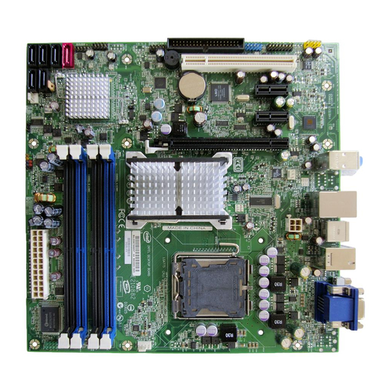
Intel Desktop Board DQ35JO Product Guide Desktop Board Components Figure 1 shows the approximate location of the major components on Desktop Board DQ35JO. Figure 1. Desktop Board DQ35JO Components... -
Page 13: Desktop Board Dq35Jo Components
Desktop Board Features Table 2. Desktop Board DQ35JO Components Label Description Front panel audio header Speaker PCI bus connector PCI Express x1 connector 2 Battery PCI Express x1 connector 1 PCI Express x16 connector Rear chassis fan header (3-pin) Back panel connectors 12 V processor core voltage connector (2 x 2 pin) Processor socket Processor fan header (4-pin) -
Page 14: Processor
Desktop Board may result in damage to the board, or the system may not function properly. Desktop Board DQ35JO supports an Intel processor in the LGA775 package. Processors are not included with the Desktop Board and must be purchased separately. -
Page 15: Intel Q35 Express Chipset
DMI interconnect. The component also provides integrated graphics capabilities supporting 3D, 2D, and display capabilities. ICH9DO is a centralized controller for the board’s I/O paths. Related Links: Go to the following link for more information about the Intel Q35 Express Chipset: http://developer.intel.com/products/chipsets/index.htm... -
Page 16: Intel Q35 Graphics Subsystem
⎯ DDC2B compliant interface with Advanced Digital Display 2 card or Media Expansion Card (ADD2/MEC), support for TV-out/TV-in and DVI digital display connections NOTE A minimum of 512 MB of system memory is required in order for the Intel GMA 3100 graphics controller to operate properly. -
Page 17: Digital Video Interface (Dvi)
A signal-to-noise (S/N) ratio of ≤95 dB playback quality and ≤90 dB recording quality • Independent stereo audio playback from back panel connectors and the Intel High Definition Audio front panel header Related Links: Go to the following link or pages for more information about: •... -
Page 18: Legacy Input/Output (I/O) Controller
PCI power management support LAN Subsystem The LAN subsystem includes: • Intel ICH9DO • Intel 82566DM Gigabit (10/100/1000 Mb/s) Ethernet LAN controller with support for: ⎯ Intel AMT ⎯ Alert Standard Format (ASF) 2.0 ® ® ⎯ Virtual LAN driver support for Intel... -
Page 19: Rj-45 Lan Connector Leds
AMT) Intel AMT offers IT organizations tamper-resistant and persistent management capabilities. Intel AMT is a hardware-based solution that uses out of band communication to manage access to client systems in addition to offering encrypted and persistent asset management and remote diagnostics and/or recovery capabilities for networked platforms. -
Page 20: Intel Amt Status Indicator
Software with Intel AMT capability is required to take advantage of the Intel AMT platform management capabilities. Related Links: Go to the following link for information about Intel AMT and the availability of third- party software: http://www.intel.com/go/iamt Intel AMT Status Indicator The Intel AMT status indicator (red LED) shows the current state of the Intel Management Engine. -
Page 21: Hi-Speed Usb 2.0 Support
• RAID 1 - data mirroring • RAID 0+1 (or RAID 10) - data striping and mirroring • RAID 5 - distributed parity ® For information on configuring your system for RAID using Intel Matrix Storage Technology see Chapter 4. -
Page 22: Intel Rapid Recover Technology
Intel Rapid Recover Technology Intel Rapid Recover Technology enables fast and easy recovery of your data in the event of a hard drive failure. It allows you to maintain a complete copy of your primary or master drive onto a second hard drive, the recovery drive. If the master hard drive should fail, either from a mechanical failure or the result of a virus, recovery is as simple as booting from the recovery drive. -
Page 23: Security Passwords
Desktop Board Features Security Passwords The BIOS includes security features that restrict whether the BIOS Setup program can be accessed and who can boot the computer. A supervisor password and a user password can be set for the BIOS Setup and for booting the computer, with the following restrictions: •... -
Page 24: Hard Disk Drive Password Feature During Bios Post
Intel Desktop Board DQ35JO Product Guide Hard Disk Drive Password Feature During BIOS POST During every BIOS POST execution, if a User hard disk drive password is present on the hard drive, POST execution will pause to prompt the user to enter the Master or... -
Page 25: Hardware Monitoring And Fan Speed Control
• Intel Quiet System Technology fan speed control, delivering acoustically-optimized thermal management NOTE Memory must be installed in the Channel A, DIMM 0 socket to enable Intel Quiet System Technology. • Fan speed controllers and sensors integrated into the ICH9DO •... -
Page 26: Acpi
Intel Desktop Board DQ35JO Product Guide ACPI ACPI gives the operating system direct control over the power management and Plug and Play functions of a computer. The use of ACPI with the Desktop Board requires an operating system that provides full ACPI support. -
Page 27: Lan Wake Capabilities
Desktop Board DQ35JO supports waking the Intel Management Engine over the network. This can be enabled in the BIOS and allows Intel AMT to be remotely turned on through a wake packet generated by a management console application or a ping. -
Page 28: +5 V Standby Power Indicator
Intel Desktop Board DQ35JO Product Guide The Desktop Board supports the PCI Bus Power Management Interface Specification. Add-in cards that support this specification can participate in power management and can be used to wake the computer. +5 V Standby Power Indicator... -
Page 29: Pme# Signal Wake-Up Support
ENERGY STAR* Capable The US Department of Energy and the US Environmental Protection Agency have recently revised the ENERGY STAR requirements. Intel worked directly with these governmental agencies to define the new requirements. Currently, Intel Desktop Boards are capable of meeting the new ENERGY STAR requirements depending on system configuration. - Page 30 Intel Desktop Board DQ35JO Product Guide...
-
Page 31: Installing And Replacing Desktop Board Components
2 Installing and Replacing Desktop Board Components This chapter tells you how to: • Install the I/O shield • Install and remove the Desktop Board • Install and remove a processor • Install and remove memory • Install and remove a PCI Express x16 card •... -
Page 32: Installation Precautions
Intel Desktop Board DQ35JO Product Guide Installation Precautions When you install and test the Intel Desktop Board, observe all warnings and cautions in the installation instructions. To avoid injury, be careful of: • Sharp pins on connectors • Sharp pins on printed circuit assemblies •... -
Page 33: Installing The I/O Shield
Installing and Replacing Desktop Board Components Installing the I/O Shield The Desktop Board comes with an I/O shield. When installed in the chassis, the shield blocks radio frequency transmissions, protects internal components from dust and foreign objects, and promotes correct airflow within the chassis. Install the I/O shield before installing the Desktop Board in the chassis. -
Page 34: Installing And Removing The Desktop Board
Intel Desktop Board DQ35JO Product Guide Installing and Removing the Desktop Board CAUTION Only qualified technical personnel should do this procedure. Disconnect the computer from its power source before performing the procedures described here. Failure to disconnect the power before you open the computer can result in personal injury or equipment damage. -
Page 35: Installing And Removing A Processor
Installing and Replacing Desktop Board Components Installing and Removing a Processor Instructions on how to install the processor to the Desktop Board are given below. Installing a Processor CAUTION Before installing or removing the processor, make sure the AC power has been removed by unplugging the power cord from the computer;... -
Page 36: Lift The Load Plate
Intel Desktop Board DQ35JO Product Guide 3. Lift the load plate (Figure 8, A). Do not touch the socket contacts (Figure 8, B). Figure 8. Lift the Load Plate 4. Remove the plastic protective socket cover from the load plate (Figure 9). Do not discard the protective socket cover. -
Page 37: Remove The Processor From The Protective Processor Cover
Installing and Replacing Desktop Board Components 5. Remove the processor from the protective processor cover. Hold the processor only at the edges, being careful not to touch the bottom of the processor (see Figure 10). Do not discard the protective processor cover. Always replace the processor cover if the processor is removed from the socket. -
Page 38: Installing The Processor Fan Heat Sink
Intel Desktop Board DQ35JO Product Guide 7. Pressing down on the load plate (Figure 12, A), close and engage the socket lever (Figure 12, B). Figure 12. Close the Load Plate Installing the Processor Fan Heat Sink Desktop Board DQ35JO has mounting holes for a processor fan heat sink. For instructions on how to attach the processor fan heat sink to the Desktop Board, refer to the boxed processor manual. -
Page 39: Connecting The Processor Fan Heat Sink Cable
Installing and Replacing Desktop Board Components Connecting the Processor Fan Heat Sink Cable Connect the processor fan heat sink cable to the 4-pin processor fan header (see Figure 13). A fan with a 4-pin connector as shown in Figure 13, A is recommended; however, a fan with a 3-pin connector (Figure 13, B) can be used. -
Page 40: Removing The Processor
DIMM 1 in both Channel A and Channel B. NOTE Regardless of the memory configuration used (dual or single channel), Channel A, DIMM 0 must always be populated. This is a requirement of the Intel Management Engine feature. Guidelines for Dual Channel Memory Configuration Before installing DIMMs, read and follow these guidelines for dual channel configuration. -
Page 41: Three Dimms
Installing and Replacing Desktop Board Components If additional memory is to be used, install another matched pair of DIMMs in DIMM 1 (black) in channels A and B (see Figure 15). Figure 15. Dual Channel Memory Configuration with Four DIMMs Three DIMMs If you want to use three DIMMs in a dual-channel configuration, install a matched pair of DIMMs equal in speed and size in DIMM 0 (blue) and DIMM 1 (black) of channel A. -
Page 42: Installing Dimms
Intel Desktop Board DQ35JO Product Guide Installing DIMMs To make sure you have the correct DIMM, place it on the illustration of the DDR2 DIMM in Figure 17. All the notches should match with the DDR2 DIMM. Figure 17. Use DDR2 DIMMs... -
Page 43: Installing A Dimm
Installing and Replacing Desktop Board Components NOTE Memory must be installed in the Channel A, DIMM 0 socket to enable Intel Quiet System Technology. To install a DIMM, follow these steps: 1. Observe the precautions in "Before You Begin" on page 31. -
Page 44: Removing Dimms
Intel Desktop Board DQ35JO Product Guide 7. Insert the bottom edge of the DIMM into the socket. 8. When the DIMM is inserted, push down on the top edge of the DIMM until the retaining clips snap into place. Make sure the clips are firmly in place. -
Page 45: Installing And Removing A Pci Express X16 Card
Installing and Replacing Desktop Board Components Installing and Removing a PCI Express x16 Card CAUTION When installing a PCI Express x16 card on the Desktop Board, ensure that the card is fully seated in the PCI Express x16 connector before you power on the system. If the card is not fully seated in the PCI Express connector, an electrical short may result across the PCI Express connector pins. -
Page 46: Removing The Pci Express X16 Card
Intel Desktop Board DQ35JO Product Guide Removing the PCI Express x16 Card Follow these instructions to remove the PCI Express x16 card from the connector: 1. Observe the precautions in "Before You Begin" on page 31. 2. Remove the screw (Figure 20, A) that secures the card’s metal bracket to the chassis back panel. -
Page 47: Connecting The Ide Cable
• Observe the precautions in "Before You Begin" on page 31. • Attach the cable end with the single connector (blue) to the Intel Desktop Board (Figure 21, A). • Attach the cable end with the two closely spaced connectors (gray and black) to the drives (Figure 21, B). -
Page 48: Connecting The Serial Ata (Sata) Cables
Intel Desktop Board DQ35JO Product Guide Connecting the Serial ATA (SATA) Cables SATA cables support the Serial ATA protocol. Each cable can be used to connect a single internal SATA drive to the Desktop Board. For correct cable function: 1. Observe the precaution in “Before You Begin” on page 31. -
Page 49: Installing The External Serial Ata Adapter Bracket
Installing and Replacing Desktop Board Components Installing the External Serial ATA Adapter Bracket If you are connecting the external Serial ATA (eSATA) adapter bracket to the Desktop Board, follow these instructions (see Figure 23): 1. Observe the precautions in “Before You Begin” on page 31. 2. -
Page 50: Connecting To The Internal Headers
Intel Desktop Board DQ35JO Product Guide Connecting to the Internal Headers Before connecting cables to the internal headers, observe the precautions in “Before You Begin” on page 31. Figure 24 shows the location of the internal headers. Item Description Item... -
Page 51: Connecting To The Hd Audio Link Header
Definition Audio Figure 24, B shows the location of the front panel audio header. Table 8 shows the pin assignments for the front panel audio header. Table 8. Front Panel Intel High Definition Audio Header Signal Names Signal Name Signal Name... -
Page 52: Connecting To The Serial Port Header
Intel Desktop Board DQ35JO Product Guide To install the cable that connects the front panel audio solution to the front panel audio header, follow these steps: 1. Observe the precautions in "Before You Begin" on page 31. 2. Turn off all peripheral devices connected to the computer. Turn off the computer and disconnect the AC power cord. -
Page 53: Connecting To The Alternate Front Panel Power Led Header
Installing and Replacing Desktop Board Components Connecting to the Alternate Front Panel Power LED Header Figure 24, F on page 50 shows the location of the alternate front panel power LED header. Pins 1 and 3 of this header duplicate the signals on pins 2 and 4 of the front panel header. -
Page 54: Connecting To The Usb 2.0 Headers
USB device. Connecting to the Audio System After installing the RealTek audio driver from the Intel Express Installer DVD-ROM, the multi-channel audio feature can be enabled. Figure 25 shows the back panel audio connectors. The default connector assignments are shown in the table. -
Page 55: Connecting Chassis Fan And Power Supply Cables
Installing and Replacing Desktop Board Components NOTE The back panel audio line out connector is designed to power either headphones or amplified speakers only. Poor audio quality may occur if passive (non-amplified) speakers are connected to this output. Connecting Chassis Fan and Power Supply Cables Connecting Chassis Fan Cables Connect chassis fan cables to the 3-pin chassis fan headers on the Desktop Board. -
Page 56: Connecting Supply Power Cables
Intel Desktop Board DQ35JO Product Guide Connecting Supply Power Cables CAUTION Failure to use an appropriate power supply and/or not connecting the 12 V (2 x 2 pin) power connector to the Desktop Board may result in damage to the board or the system may not function properly. -
Page 57: Setting The Bios Configuration Jumper
Installing and Replacing Desktop Board Components Setting the BIOS Configuration Jumper NOTE Always turn off the power and unplug the power cord from the computer before moving the jumper. Moving the jumper with the power on may result in unreliable computer operation. -
Page 58: Clearing Or Changing Passwords
Intel Desktop Board DQ35JO Product Guide Table 14. Jumper Settings for the BIOS Setup Program Modes Jumper Setting Mode Description Normal (default) (1-2) The BIOS uses the current configuration and passwords for booting. Configure (2-3) After the Power-On Self-Test (POST) runs, the BIOS displays the Maintenance Menu. -
Page 59: Clearing Or Changing Hard Disk Drive Passwords
Installing and Replacing Desktop Board Components 6. Replace the cover, plug in the computer, turn on the computer, and allow it to boot. 7. The computer starts the Setup program. Setup displays the Maintenance menu. 8. Use the arrow keys to select Clear Passwords. Press <Enter> and Setup displays a pop-up screen requesting that you confirm clearing the password. -
Page 60: Replacing The Battery
Intel Desktop Board DQ35JO Product Guide Replacing the Battery A coin-cell battery (CR2032) powers the real-time clock and CMOS memory. When the computer is not plugged into a wall socket, the battery has an estimated life of three years. When the computer is plugged in, the standby current from the power supply extends the life of the battery. - Page 61 Installing and Replacing Desktop Board Components VORSICHT Bei falschem Einsetzen einer neuen Batterie besteht Explosionsgefahr. Die Batterie darf nur durch denselben oder einen entsprechenden, vom Hersteller empfohlenen Batterietyp ersetzt werden. Entsorgen Sie verbrauchte Batterien den Anweisungen des Herstellers entsprechend. AVVERTIMENTO Esiste il pericolo di un esplosione se la pila non viene sostituita in modo corretto.
- Page 62 Intel Desktop Board DQ35JO Product Guide VIGYAZAT Ha a telepet nem a megfelelő típusú telepre cseréli, az felrobbanhat. A telepeket lehetőség szerint újra kell hasznosítani. A használt telepeket a helyi környezetvédelmi előírásoknak megfelelően kell kiselejtezni. AWAS Risiko letupan wujud jika bateri digantikan dengan jenis yang tidak betul. Bateri sepatutnya dikitar semula jika boleh.
- Page 63 Installing and Replacing Desktop Board Components UYARI Yanlış türde pil takıldığında patlama riski vardır. Piller mümkün olduğunda geri dönüştürülmelidir. Kullanılmış piller, yerel çevre yasalarına uygun olarak atılmalıdır. OСТОРОГА Використовуйте батареї правильного типу, інакше існуватиме ризик вибуху. Якщо можливо, використані батареї слід утилізувати. Утилізація використаних батарей...
- Page 64 Intel Desktop Board DQ35JO Product Guide To replace the battery, follow these steps: 1. Observe the precautions in "Before You Begin" (see page 31). 2. Turn off all peripheral devices connected to the computer. Disconnect the computer’s power cord from the AC power source (wall outlet or power adapter).
-
Page 65: Updating The Bios
Power-On Self-Test (POST) memory test begins and before the operating system boot begins. This chapter tells you how to update the BIOS by either using the Intel Express BIOS Update utility or the Iflash Memory Update utility, and how to recover the BIOS if an update fails. -
Page 66: Updating The Bios With The Iso Image Bios Update File Or The Iflash Memory Update Utility
Intel Flash Memory Update Utility You can obtain either of these files through your computer supplier or by navigating to the Desktop Board DQ35JO page on the Intel World Wide Web site at: http://support.intel.com/support/motherboards/desktop Navigate to the DQ35JO page, click “[view] Latest BIOS updates,” and select the ISO Image BIOS Update or Iflash BIOS Update utility file. -
Page 67: Updating The Bios With The Iflash Memory Update Utility
CD-ROM, bootable USB flash drive, or other bootable USB media. The utility available on the Intel World Wide Web site provides a simple method for creating a bootable CD-ROM that will automatically update your BIOS. The Iflash BIOS update files can also be extracted locally to your hard drive and copied to a bootable USB flash drive or other bootable USB media. -
Page 68: Recovering The Bios
BIOS could be damaged. Due to BIOS size and recovery requirements, a CD-R or USB Flash drive with the .BIO file in the root directory will be required. Related Links: For more information about updating the Intel Desktop Board BIOS or recovering from a BIOS update failure, go to: http://support.intel.com/support/motherboards/desktop/sb/CS-022312.htm... -
Page 69: Configuring For Raid (Intel Matrix Storage Technology)
4. Then save your settings by pressing <F10>. Creating Your RAID Set 1. Upon re-boot, you will see the following Intel Matrix Storage Manager option ROM status message on the screen: Press <Ctrl-I> to enter the RAID Configuration Utility. Press <Ctrl-I> and enter the RAID Configuration Utility. -
Page 70: Loading The Intel Matrix Storage Technology Raid Drivers And Software
"Where do you want to install Windows?". Click on the "Load Drivers" option and insert the Intel Express Installer CD/DVD into your optical drive or insert the diskette labeled Intel Matrix Storage Technology RAID Driver into a USB floppy drive. -
Page 71: Configuring For Intel Rapid Recover Technology
NOTE Intel Rapid Recover Technology does not support RAID 5. Intel Rapid Recover Technology can be Enabled or Disabled in the system BIOS menu. To enable Intel Rapid Recover Technology, complete following steps: 1. Enter the BIOS menu by pressing the <F2> key early during system POST. -
Page 72: Creating A Recovery Volume
Creating a Recovery Volume Using the Intel Matrix Storage Console To create a recovery volume using the Intel Matrix Storage Console, the system must be configured in RAID mode with two drives. Boot the system into Microsoft Windows and open the Intel Matrix Storage Console application. -
Page 73: Disk Synchronization Mode
There are two modes of updating or synchronizing the recovery disk with the master disk – either continuous update or manual update. To change from Continuous Update mode to Update On Request mode using the Intel Matrix Storage Console, select the Advanced mode from the View menu, right-click on the recovery volume, and select Disable Continuous Update. - Page 74 To un-mount the recovery disk, complete the following steps: 1. In the Advanced mode, right-click on the recovery volume name. 2. Select Access Recovery Drive Files. 3. Select OK on the information dialog box. The recovery disk is now un-mounted and reappears in Intel Matrix Storage Console.
-
Page 75: A Error Messages And Indicators
A Error Messages and Indicators Desktop Board DQ35JO reports POST errors in two ways: • By sounding a beep code • By displaying an error message on the monitor BIOS Beep Codes The BIOS also issues a beep code (one long tone followed by two short tones) during POST if the video configuration fails (a faulty video card or no card installed) or if an external ROM module does not properly checksum to zero. - Page 76 Intel Desktop Board DQ35JO Product Guide...
-
Page 77: B Regulatory Compliance
B Regulatory Compliance This appendix contains the following regulatory compliance information for Desktop Board DQ35JO: • Safety standards • European Union Declaration of Conformity statement • Product Ecology statements • Electromagnetic Compatibility (EMC) regulations • Product certifications Safety Standards Desktop Board DQ35JO complies with the safety standards stated in Table 17 when correctly installed in a compatible host system. -
Page 78: European Union Declaration Of Conformity Statement
Intel Desktop Board DQ35JO Product Guide European Union Declaration of Conformity Statement We, Intel Corporation, declare under our sole responsibility that the product Intel ® Desktop Board DQ35JO is in conformity with all applicable essential requirements necessary for CE marking, following the provisions of the European Council Directives 2004/108/EC (EMC Directive) and 2006/95/EC (Low Voltage Directive). -
Page 79: Product Ecology Statements
The following information is provided to address worldwide product ecology concerns and regulations. Recycling Considerations As part of its commitment to environmental responsibility, Intel has implemented the Intel Product Recycling Program to allow retail consumers of Intel’s branded products ®... - Page 80 Français Dans le cadre de son engagement pour la protection de l'environnement, Intel a mis en œuvre le programme Intel Product Recycling Program (Programme de recyclage des produits Intel) pour permettre aux consommateurs de produits Intel de recycler les produits usés en les retournant à...
-
Page 81: Lead-Free Desktop Board
Regulatory Compliance Portuguese Como parte deste compromisso com o respeito ao ambiente, a Intel implementou o Programa de Reciclagem de Produtos para que os consumidores finais possam enviar produtos Intel usados para locais selecionados, onde esses produtos são reciclados de maneira adequada. - Page 82 Intel Desktop Board DQ35JO Product Guide Table 18 shows the lead-free board markings as they appear on the board and accompanying collateral. Table 18. Lead-Free Board Markings Description Mark Lead-Free 2 Level Interconnect: This symbol is used to identify electrical...
-
Page 83: Emc Regulations
Regulatory Compliance EMC Regulations Desktop Board DQ35JO complies with the EMC regulations stated in Table 19 when correctly installed in a compatible host system. Table 19. EMC Regulations Regulation Title FCC 47 CFR Part 15, Title 47 of the Code of Federal Regulations, Part 15, Subpart B, Subpart B Radio Frequency Devices. -
Page 84: Ensure Electromagnetic Compatibility (Emc) Compliance
Intel Desktop Board DQ35JO Product Guide Korean Class B statement translation: This is household equipment that is certified to comply with EMC requirements. You may use this equipment in residential environments and other non-residential environments. Ensure Electromagnetic Compatibility (EMC) Compliance... -
Page 85: Product Certifications
Description Mark UL joint US/Canada Recognized Component mark. Includes adjacent UL file number for Intel Desktop Boards: E210882. FCC Declaration of Conformity logo mark for Class B equipment. Includes Intel name and DQ35JO model designation. CE mark. Declaring compliance to European Union (EU) EMC directive and Low Voltage directive. -
Page 86: Chassis And Component Certifications
Intel Desktop Board DQ35JO Product Guide Chassis and Component Certifications Ensure that the chassis and certain components; such as the power supply, peripheral drives, wiring, and cables; are components certified for the country or market where used. Agency certification marks on the product are proof of certification. Typical...