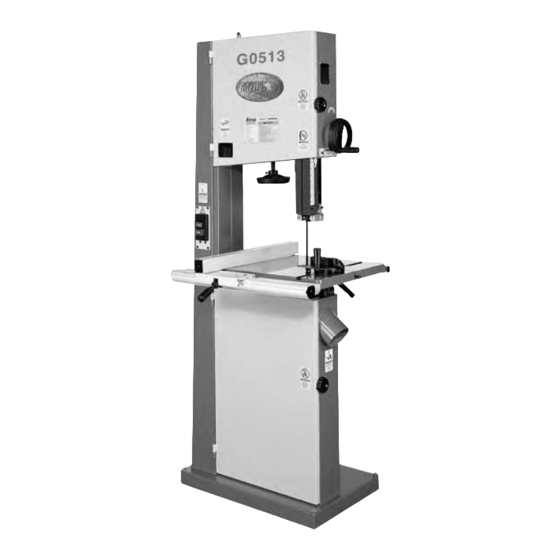
Grizzly G0513 Owner's Manual
17" & 19" heavy duty bandsaws
Hide thumbs
Also See for G0513:
- Owner's manual (108 pages) ,
- Instruction manual (56 pages) ,
- Parts list (8 pages)

Related Manuals for Grizzly G0513


Summary of Contents for Grizzly G0513
- Page 1 MODEL G0513/G0514 17" & 19" HEAVY DUTY BANDSAWS OWNER'S MANUAL G0513 G0514 WARNING: NO PORTION OF THIS MANUAL MAY BE REPRODUCED IN ANY SHAPE OR FORM WITHOUT THE WRITTEN APPROVAL OF GRIZZLY INDUSTRIAL, INC.
- Page 2 This manual provides critical safety instructions on the proper setup, operation, maintenance, and service of this machine/tool. Save this document, refer to it often, and use it to instruct other operators. Failure to read, understand and follow the instructions in this manual may result in fire or serious personal injury—including amputation, electrocution, or death.
-
Page 3: Table Of Contents
Table of Contents INTRODUCTION ..........2 SECTION 5: ACCESSORIES ......36 SECTION 6: MAINTENANCE ......38 SECTION 1: SAFETY ........9 SECTION 7: SERVICE ........40 SECTION 2: CIRCUIT REQUIREMENTS ..12 SECTION 3: SETUP ........13 SECTION 8: WIRING ........53 SECTION 9: PARTS ........ -
Page 4: Introduction
INTRODUCTION Manual Accuracy Contact Info your machine may not exactly match the manual Machine Description www.grizzly.com... - Page 5 Identification Figure 2. Figure 1. Figure 3. To reduce the risk of serious injury when using this machine, read and understand this entire manual before beginning any operations.
-
Page 6: Figure
Blade Tension Scale Wheel Brush Figure 4 Figure 6 Figure 6. Figure 4. Tension Lever Adjustment Screw Figure 5 Figure 5. -
Page 7: Machine Data Sheet
MACHINE DATA SHEET Customer Service #: (570) 546-9663 · To Order Call: (800) 523-4777 · Fax #: (800) 438-5901 MODEL G0513 17" BANDSAW - 2 HP Weight................................266 lbs. Length/Width/Height..........................32 x 32 x 73 in. Foot Print (Length/Width)........................27 x 17-3/4 in. Type.............................. - Page 8 Standard Blade Length........................131-1/2 in. Blade Width Range..........................1/8 - 1 in. Upper Blade Guides...................... Roller Disc/Ball Bearing Lower Blade Guides...................... Roller Disc/Ball Bearing Guide Post Size........................1.180 in. (30mm) Guide Post Type..................Sq. Tubing, 0.075 in. Wall Thickness Table Length.............................. 17 in. Table Width..............................
- Page 9 MACHINE DATA SHEET Customer Service #: (570) 546-9663 · To Order Call: (800) 523-4777 · Fax #: (800) 438-5901 MODEL G0514 19" HEAVY-DUTY BANDSAW - 2 HP Weight................................319 lbs. Length/Width/Height..........................36 x 32 x 78 in. Foot Print (Length/Width)......................... 29-1/2 x 17-3/4 in. Type..............................
- Page 10 Standard Blade Length..........................143 in. Blade Width Range........................1/8 - 1-1/4 in. Upper Blade Guides...................... Roller Disc/Ball Bearing Lower Blade Guides...................... Roller Disc/Ball Bearing Guide Post Size........................1.180 in. (30mm) Guide Post Type..................Sq. Tubing, 0.075 in. Wall Thickness Table Length.............................. 19 in. Table Width..............................
-
Page 11: Section 1: Safety
SECTION 1: SAFETY For Your Own Safety, Read Instruction Manual Before Operating this Machine The purpose of safety symbols is to attract your attention to possible hazardous conditions. This manual uses a series of symbols and signal words intended to convey the level of importance of the safety messages. -
Page 12: Safety Instructions For Machinery
Safety Instructions for Machinery DISCONNECTING POWER SUPPLY. APPROVED OPERATION. INTENDED USE. CHILDREN & BYSTANDERS. STABLE MACHINE. FEED DIRECTION. SECURING WORKPIECE. FORCING MACHINERY. UNATTENDED OPERATION. GUARDS & COVERS. MAINTENANCE & INSPECTION. REMOVING TOOLS. AWKWARD POSITIONS. EXPERIENCING DIFFICULTIES. DANGEROUS ENVIRONMENTS. -
Page 13: Additional Safety For Bandsaws
Additional Safety for Bandsaws BLADE CONDITION. UNATTENDED MACHINE. HAND PLACEMENT. DO NOT FORCE THE MACHINE. GUARDS. CUTTING PROPER MATERIAL. BLADE REPLACEMENT SAFETY. MAINTENANCE/SERVICE. WORKPIECE HANDLING. BLADE CONTROL CUTTING TECHNIQUES. EXPERIENCING DIFFICULTIES. BLADE SPEED. Like all machinery there is potential danger when operating this bandsaw. Accidents are frequently caused by lack of familiarity or failure to pay attention. -
Page 14: Section 2: Circuit Requirements
SECTION 2: CIRCUIT REQUIREMENTS Power Connection Device Serious personal injury could occur if you connect the machine to power before com- pleting the setup process. DO NOT connect Figure 7 the machine to the power until instructed later in this manual. L5-30 GROUNDED LOCKING RECEPTACLE... -
Page 15: Section 3: Setup
SECTION 3: SETUP Needed for Setup This machine presents serious injury hazards to untrained users. Read through this entire manu- al to become familiar with Description the controls and opera- tions before starting the Page 16 machine! Wear safety glasses dur- ing the entire setup pro- cess! Unpacking... - Page 16 Inventory Note: If you can't find an item on this list, check the mounting location on the machine or examine the packaging materials carefully. Occasionally we pre-install certain components for shipping purposes. Box 1: (Figures 8–9) Figure 8. Hardware and Tools (not shown): Figure 9.
- Page 17 Hardware Recognition Chart...
-
Page 18: Site Considerations
Clean Up Site Considerations Floor Load Machine Data Sheet Figure 10 For optimum performance, clean all moving parts or sliding contact surfaces. Placement Location Figures 11 Gasoline and petroleum products have low flash points and can explode or cause fire if used to clean machinery. - Page 19 Moving & Placing Mounting to Shop Base Unit Floor The Model G0513/G0514 is a heavy machine. Serious personal injury may occur if safe moving methods are not used. To be safe, get assistance and use power equipment to move the shipping crate and remove the machine from Bolting to Concrete Floors the crate.
- Page 20 Guide Post Blade Guides Handwheel Page 24 To install the guide post handwheel: All saw blades are dan- gerous and may cause personal injury. To reduce Figure the risk of being injured, wear leather gloves when handling saw blades. Personal injury may occur if the table is lifted without assistance.
-
Page 21: Blade Tracking
Figure 18 Blade Tracking Figure 18. Personal injury or death Be careful when turn- can occur if the machine ing the bandsaw wheel starts while your hand by hand in the next is touching the bandsaw step. The spokes may wheel during tracking have sharp edges and adjustments. -
Page 22: Positive Stop
Positive Stop Figure 19 If the blade is square with the table sur- face: Personal injury or death can occur if the bandsaw starts during table adjust- ments. Disconnect power from the bandsaw before If the blade is NOT square to the table performing table adjust- surface: ments. -
Page 23: Dust Collection
Dust Collection Fence Assembly DO NOT operate this bandsaw without an To assemble the fence: adequate dust collection system. This saw creates substantial amounts of wood dust while operating. Failure to use a dust collec- If a cap screw falls tion system can result in short and long-term inside of the rear fence rail, remove the rail respiratory illness. -
Page 24: Fence Adjustment
Fence Adjustment Figure 24 To adjust the fence parallel to the miter slot: NOTICE Adjusting the fence parallel to the miter slot does not guarantee straight cuts. The miter slot may need to be adjusted parallel to the side of the blade. Refer to the "Table Alignment"... - Page 25 Test Run Tensioning Blade Troubleshooting Page 40 To tension the bandsaw blade: Test Run To test run the machine: Note: This procedure will NOT work if the guide blocks have any contact with the blade. Page 19 Note: Always detension the blade after use to increase blade life and reduce strain on the bandsaw components.
-
Page 26: Blade Guides
Blade Guides Personal injury or death can occur if the bandsaw starts during blade guide adjustments. Disconnect power from the bandsaw before performing blade guide adjustments. Figure 26. To adjust the upper blade guide: Figure 25 Figure 27. Figure 25. Figure Figure 28 Figure 25... - Page 27 Personal injury or death can occur if the bandsaw starts during blade guide adjustments. Disconnect power from the bandsaw before performing blade guide adjustments. To adjust the lower blade guide: Figure 30 Figure 28 Figure 29 Figure 30. Figure 31 Figure 29.
- Page 28 Figure Figure 30 Figure Figure 33. Figure 33 Figure Figure 29 Figure 34. Figure 32.
-
Page 29: Section 4: Operations
WE STRONGLY REC- OMMEND that you read books, review industry trade magazines, or get formal training before beginning any projects. Regardless of the content in this section, Grizzly Industrial will not be held liable for accidents caused by lack of training. -
Page 30: Guide Post
START/STOP Switch Guide Post Figure 36 Figures 35 Figure 35. Figure 36. To adjust guide post: Figure 36... -
Page 31: Fine Tune Tracking
Fine Tune Tracking Table Tilt NOTICE Adjusting the final blade tracking setting Personal injury or death requires the machine to be turned ON. can occur if the bandsaw starts during table adjust- ment. Disconnect power To fine tune the tracking: from the bandsaw before performing table adjust- Blade Tracking... - Page 32 Ripping Crosscutting To make a rip cut: To make a 90˚ crosscut: Figure 39 Note: If you are cutting nar- row pieces, use a push stick to protect your fingers. Figure 40 Figure 39. Figure 40. NEVER place fingers or hands in the line of cut.
-
Page 33: Cutting Curves
Resawing Cutting Curves NOTICE Resawing requires the blade to be perpen- dicular to the table surface. Instructions on making the blade perpendicular to the table surface are in SECTION 3: SETUP. Figure 41 To make a resaw cut: NOTICE The list below displays blade widths and the corresponding minimum radii for those blade widths. - Page 34 Stacked Cuts Blade Speed To complete a stacked cut: To adjust the blade speed: Figure 43 Figure 42 Figure 43. Figure 42.
- Page 35 Figure 44 Blade Information Blade Length Page 36 Figure 44. Blade Width Figure 45 Curve Cutting: Figure 46 Figure 45. Figure 46.
- Page 36 Straight Cutting: Hook: Tooth Pitch Tooth Style Figure 47 Blade Care Figure 47. Raker: Blade Breakage Skip:...
-
Page 37: Blade Changes
The most common causes of blade breakage are: To replace a blade: Note: If the teeth will not point downward in any orientation, the blade is inside-out. Put on heavy gloves, remove the blade, and twist it right side-out. Figure 48 Blade Changes Always disconnect power to the machine when... -
Page 38: Section 5: Accessories
SECTION 5: ACCESSORIES Replacement Blades 143" Carbon Steel Replacement Blades for the Model G0514. MODEL WIDTH ⁄ " Carbon Steel Replacement Blades for the Model G0513 MODEL WIDTH G7314Z—Heavy-Duty Mobile Base G1163—1HP Dust Collector Figure 50. Figure 49. - Page 39 T10117—Big Mouth Dust Hood with Stand H2499—Small Half-Mask Respirator H3631—Medium Half-Mask Respirator H3632—Large Half-Mask Respirator H3635—Cartridge Filter Pair P100 Figure 51. T20501—Face Shield Crown Protector 4" Figure 53. T20502—Face Shield Crown Protector 7" T20503—Face Shield Window T20452—"Kirova" Anti-Reflective S. Glasses G5562—SLIPIT ®...
-
Page 40: Section 6: Maintenance
SECTION 6: MAINTENANCE Cleaning Always disconnect power to the machine before performing maintenance. Failure to do this may result in serious person- al injury. Schedule Unpainted Cast Iron Daily Check: Section 5: Accessories Page 36 Monthly Check: Wheel Brush Adjusting Wheel Brush Page 46... - Page 41 Lubrication To remove and clean the bearings: Figure 55. Figure 55...
-
Page 42: Section 7: Service
SECTION 7: SERVICE Troubleshooting Page 54... - Page 43 Page 44. Page 35 Page 45 Page 48 Page 45 Page...
- Page 44 Page 35 Page 35 Page 23 Page Page 35 Page 19 Page 35 Page Page 48 Page 35 Page 22...
- Page 45 Page 19 Page 48 Page 23 Page 24 Page 27 Page 23 Page 35 Page 28...
- Page 46 Checking V-Belt Tensioning V-Belt Tools Needed: To tension the V-belt: To check the V-belt: Figure 57 Figure 56 Figure 57. Steps 3 & 4 Figure 56.
- Page 47 Replacing V-Belt Tools Needed: To replace the V-belt: Tensioning V-Belt Page 44 Figure 57 Figure 58 Figure 58.
- Page 48 Figure Adjusting Tension Lever Adjusting Wheel Brush Figure 59 Figure 60 Figure 59 Tools Needed: To adjust the tension lever, do these steps: Figure 60. Tools Needed: Blade To adjust the wheel brush: Changes Page 35...
- Page 49 Blade Lead Figure 61 To shift the table: Figure 61. To correct blade lead: Steps 1–4 To skew your fence:...
-
Page 50: Aligning Wheels
Aligning Wheels Components and Hardware Needed: Tools Needed: Figure 62 Checking Coplanarity Figure 62 Note: For best results, straighten the 2x4 with a jointer before cutting. Figure 62. Coplanarity Gauge Positions Gauge Tracking Knob Page 35 Wheels Adjustment Figure 63. Figure 63... - Page 51 Figure 1 A Figure 1 Figure 1, C Figure 1, Shimming Upper Wheel Figure 2 Step 3 Figure 1 Note: When wheels are properly coplanar, Figure 2 the blade may not be centered on the crown of the wheel, but it will be balanced.
- Page 52 Adjusting Lower Adjusting Guide Wheel Post Travel Tools Needed: Tools Needed: To adjust the lower wheel: To check/adjust the guide post parallel side- to-side with the blade: Figure 64 Figure 65 Figure 64. Figure 65.
- Page 53 Figure 67 Figure 66 To check/adjust the guide post parallel with the blade front-to-back: Figure 68 Figure 66 Step 7 Figure 67 Figure 68 Figure 68 Steps 4–5 Step 9 Steps 4–5 Step 6 Figure 67.
- Page 54 Figure 67 Steps 4 5 Step Figure 67 Figure 69 Step 3 Figure 69...
-
Page 55: Section 8: Wiring
SHOCK HAZARD. MODIFICATIONS. MOTOR WIRING. QUALIFIED ELECTRICIAN. CAPACITORS. WIRE CONNECTIONS. CIRCUIT REQUIREMENTS. Page 12 WIRE/COMPONENT DAMAGE. EXPERIENCING DIFFICULTIES. The photos and diagrams included in this section are best viewed in color. You can view these pages in color at www.grizzly.com. - Page 56 G0513/G0514 Wiring Diagram Ground Neutral 110 VAC L5-30 Plug (As Recommended) Ground 220 VAC 6-15 Plug (As Recommended) Figure 70 Figure 71 Motor @220V The motor wiring shown here is current at the time of printing, but it match your machine.
-
Page 57: Section 9: Parts
SECTION 9: PARTS Main... -
Page 58: Main Parts List
Main Parts List REF PART # DESCRIPTION REF PART # DESCRIPTION P0513004 LIFTING RING M10 PB04M HEX BOLT M6-1 X 10 P0513005 MACHINE BODY PW03M FLAT WASHER 6MM P0514005 MACHINE BODY P0513058 BRUSH PW03M FLAT WASHER 6MM PB10M HEX BOLT M6-1 X 25 PWRCRD220L POWER CORD 12GA 3WIRE P0513060 STAR HANDLE... - Page 59 Table REF PART # DESCRIPTION REF PART # DESCRIPTION PLW04M LOCK WASHER 8MM P0513118 LOCK HANDLE PW01M FLAT WASHER 8MM PW01M FLAT WASHER 8MM PB14M HEX BOLT M10-1.5 X 35 P0513120 POINTER PN02M HEX NUT M10-1.5 P0513121 TRUNNION PLATE P0513100 SMALL GEAR PLW04M LOCK WASHER 8MM...
- Page 60 Fence REF PART # DESCRIPTION REF PART # DESCRIPTION P0513201 LARGE FENCE RAIL P0555313 LOCK MECHANISM P0514201 LARGE FENCE RAIL P0514213 LOCK MECHANISM P0513202 ADJUSTABLE BASE P0513214 SMALL FENCE RAIL P0514202 ADJUSTABLE BASE P0514214 SMALL FENCE RAIL P0513203 FIXED SHAFT PN01M HEX NUT M6-1 P0514203...
- Page 61 Blade Guide...
- Page 62 Blade Guide Parts List REF PART # DESCRIPTION REF PART # DESCRIPTION PSS07M SET SCREW M5-.8 X 5 P0513160 LOCATE BUSHING P0513125 COMPLETE FENCE KIT WITH RAILS P0513161 BUSHING P0514125 COMPLETE FENCE KIT WITH RAILS PSB14M CAP SCREW M8-1.25 X 20 P0513134 LOWER ADJUST SHAFT PLW04M...
-
Page 63: Label Placement
MUST maintain the original location and readability of the labels on the machine. If any label is removed or becomes unreadable, REPLACE that label before using the machine again. Contact Grizzly at (800) 523-4777 or www.grizzly.com to order new labels. -
Page 64: Warranty Card
WARRANTY CARD The following information is given on a voluntary basis. It will be used for marketing purposes to help us develop better products and services. Of course, all information is strictly confidential. Note: We never use names more than 3 times. _____________________________________________________________________ _________________________________________________________________________________ _________________________________________________________________________________... -
Page 66: Warranty And Returns
WARRANTY AND RETURNS... - Page 68 ® Buy Direct and Save with Grizzly – Trusted, Proven and a Great Value! ~Since 1983~ Visit Our Website Today For Current Specials! ORDER 24 HOURS A DAY! 1-800-523-4777...