Table of Contents
Advertisement
Quick Links
See also:
Setup Manual
Intel® Desktop Board
DH77EB
Technical Product Specification
June 2012
Part Number: G53909-002
The Intel Desktop Board DH77EB may contain design defects or errors known as errata that may cause the product to deviate from published specifications.
Current characterized errata are documented in the Intel Desktop Board DH77EB Specification Update.
Advertisement
Table of Contents

Related Manuals for Intel DH77EB


Summary of Contents for Intel DH77EB
- Page 1 Part Number: G53909-002 The Intel Desktop Board DH77EB may contain design defects or errors known as errata that may cause the product to deviate from published specifications. Current characterized errata are documented in the Intel Desktop Board DH77EB Specification Update.
-
Page 2: Revision History
“undefined.” Intel reserves these for future definition and shall have no responsibility whatsoever for conflicts or incompatibilities arising from future changes to them. Intel desktop boards may contain design defects or errors known as errata, which may cause the product to deviate from published specifications. Current characterized errata are available on request. - Page 3 Board Identification Information Basic Desktop Board DH77EB Identification Information AA Revision BIOS Revision Notes EBH7710H.86A.0041 G39073-303 EBH7710H.86A.0053 G39073-304 EBH7710H.86A.0053 G39073-400 Notes: The AA number is found on a small label on the component side of the board. The H77 processor used on this AA revision consists of the following component:...
- Page 4 Intel Desktop Board DH77EB Technical Product Specification...
-
Page 5: Intended Audience
Intended Audience The TPS is intended to provide detailed, technical information about Intel Desktop Board DH77EB and its components to the vendors, system integrators, and other engineers and technicians who need this level of information. It is specifically not intended for general audiences. - Page 6 Intel Desktop Board DH77EB Technical Product Specification Other Common Notation Used after a signal name to identify an active-low signal (such as USBP0#) Gigabyte (1,073,741,824 bytes) GB/s Gigabytes per second Gb/s Gigabits per second Kilobyte (1024 bytes) Kilobit (1024 bits)
-
Page 7: Table Of Contents
1.3 Processor ..................16 1.3.1 Graphics Subsystem .............. 17 1.4 System Memory ................19 1.4.1 Memory Configurations ............20 ® 1.5 Intel H77 Express Chipset ..............22 1.5.1 Direct Media Interface (DMI) ..........22 1.5.2 Display Interfaces ..............22 1.5.3 USB .................. - Page 8 Intel Desktop Board DH77EB Technical Product Specification 2.3 Jumper Block ................... 57 2.4 Mechanical Considerations ..............59 2.4.1 Form Factor ................59 2.5 Electrical Considerations ..............60 2.5.1 Power Supply Considerations ..........60 2.5.2 Power Supervisor ..............60 2.5.3 Fan Header Current Capability ..........61 2.5.4...
- Page 9 13. System Memory Map................. 43 14. Component-side Connectors and Headers Shown in Figure 10 ....46 15. Front Panel Audio Header for Intel HD Audio ........47 16. Front Panel Audio Header for AC ’97 Audio ........... 47 17. Front Panel USB 2.0 Headers ............. 47 18.
- Page 10 Intel Desktop Board DH77EB Technical Product Specification 21. Chassis Intrusion Header ..............49 22. Processor, Front, and Rear Chassis (4-Pin) Fan Headers ....... 49 23. Back Panel CIR Emitter (Output) Header ..........49 24. Front Panel CIR Receiver (Input) Header ..........49 25.
-
Page 11: Product Description
• Support for a PCI Express* 3.0 x16 add-in graphics card Note: PCI Express 3.0 is only supported by 3 generation Intel Core processor family processors • 10-channel (8 + 2) Intel High Definition Audio via the Realtek* ALC892 audio Audio codec continued... - Page 12 ― Four ports implemented with stacked back panel connectors (black) ― Six front panel ports implemented through three internal headers • Six Serial ATA (SATA) ports: ― Two SATA 6.0 Gb/s interfaces through the Intel H77 Express Chipset with Intel ®...
-
Page 13: Board Layout
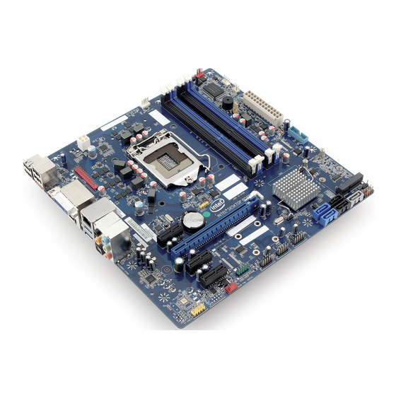
Product Description 1.1.2 Board Layout Figure 1 shows the location of the major components on Intel Desktop Board DH77EB. Figure 1. Major Board Components... -
Page 14: Components Shown In Figure 1
Intel Desktop Board DH77EB Technical Product Specification Table 2 lists the components identified in Figure 1. Table 2. Components Shown in Figure 1 Item/callout from Figure 1 Description Front panel audio header PCI Express x1 add-in card connector PCI Express x1 add-in card connector... -
Page 15: Block Diagram
Product Description 1.1.3 Block Diagram Figure 2 is a block diagram of the major functional areas of the board. Figure 2. Block Diagram... -
Page 16: Online Support
95 W Thermal Design Power (TDP). The processors listed above are only supported when falling within the wattage requirements of Intel Desktop Board DH77EB. See the Intel web site listed below for the most up-to-date list of supported processors. -
Page 17: Graphics Subsystem
Product Description 1.3.1 Graphics Subsystem The board supports graphics through either the processor Intel HD Graphics or a PCI Express x16 add-in graphics card. 1.3.1.1 Processor Graphics ® The board supports integrated graphics through the Intel Flexible Display Interface ®... -
Page 18: Pci Express X16 Graphics
Intel Desktop Board DH77EB Technical Product Specification 1.3.1.2 PCI Express x16 Graphics generation Intel Core processor family processors support PCI Express 3.0, 2.x, and 1.x and 2 generation Intel Core processor family processors support PCI Express 2.x and 1.x: PCI Express 3.0 with a raw bit rate of 8.0 GT/s results in an effective bandwidth of •... -
Page 19: System Memory
DDR3 1600 MHz, DDR3 1333 MHz, and DDR3 1066 MHz SDRAM DIMMs • Note: DDR3 1600 MHz DIMMs are only supported by 3 generation Intel Core processor family processors XMP version 1.3 performance profile support for memory speeds up to 1600 MHz •... -
Page 20: Memory Configurations
Intel Desktop Board DH77EB Technical Product Specification 1.4.1 Memory Configurations The 3 generation Intel Core processor family and 2 generation Intel Core processor family processors support the following types of memory organization: Dual channel (Interleaved) mode. This mode offers the highest throughput for •... -
Page 21: Memory Channel And Dimm Configuration
Product Description Figure 3 illustrates the memory channel and DIMM configuration. Figure 3. Memory Channel and DIMM Configuration NOTE For best memory performance always install memory in the blue DIMM sockets if installing only two DIMMs on your board. -
Page 22: Intel ® H77 Express Chipset
PCH. The display data from the frame buffer is processed in the display engine of the processor and sent to the PCH over the Intel FDI where it is transcoded as per the display protocol and driven to the display monitor. -
Page 23: Dvi Port Status Conditions
Product Description 1.5.2.3 Digital Visual Interface (DVI-I) The DVI-I port supports both digital and analog DVI displays. The maximum supported resolution is 1900 x 1200 (WUXGA). The DVI port is compliant with the DVI 1.0 specification. DVI analog output can also be converted to VGA using a DVI- VGA converter. -
Page 24: Displayport Status Conditions
Intel Desktop Board DH77EB Technical Product Specification 1.5.2.5 DisplayPort* DisplayPort is a digital communication interface that utilizes differential signaling to achieve a high bandwidth bus interface designed to support connections between PCs and monitors, projectors, and TV displays. DisplayPort is suitable for display connections between consumer electronics devices such as high definition optical disc players, set top boxes, and TV displays. -
Page 25: Usb
(LS) traffic on the bus. The board supports up to 10 USB 2.0 ports and four USB 3.0 ports. The Intel H77 Express Chipset provides the USB controller for the 2.0/3.0 ports. The port arrangement is as follows: Two USB 3.0 ports are implemented with stacked back panel connectors (blue) -
Page 26: Sata Raid
NOTE In order to use supported RAID and Intel Smart Response Technology features, you must first enable RAID in the BIOS. Also, during Microsoft Windows XP installation, you must press F6 to install the RAID drivers. See your Microsoft Windows XP documentation for more information about installing drivers during installation. -
Page 27: Real-Time Clock Subsystem
The emitter header consists of two output ports which the PC can use to emulate “learned” infrared commands in order to control external electronic hardware. Customers are required to buy or create their own interface modules to connect to Intel Desktop Boards for this feature to work. -
Page 28: Audio Subsystem
Intel H77 Express Chipset Realtek ALC892 audio codec • Front panel audio header that supports Intel HD audio and AC ’97 audio (a 2 x 5- • pin header that provides mic in and line out signals for front panel audio... -
Page 29: Back Panel Audio Connectors
Product Description S/PDIF digital audio out connector on the back panel • 5-port analog audio input/output stack on the back panel • The back panel audio connectors are configurable through the audio device drivers. The available configurable back panel audio connectors are shown in Figure 4. Item Description Rear surround... -
Page 30: Lan Subsystem
® 1.9.1 Intel 82579V Gigabit Ethernet Controller The Intel 82579V Gigabit Ethernet Controller supports the following features: • 10/100/1000 BASE-T IEEE 802.3 compliant • Energy Efficient Ethernet (EEE) IEEE802.3az support (Low Power Idle [LPI] mode) Dual interconnect between the Integrated LAN Controller and the Physical Layer •... -
Page 31: Lan Subsystem Software
Product Description 1.9.2 LAN Subsystem Software LAN software and drivers are available from Intel’s World Wide Web site. For information about Refer to Obtaining LAN software and drivers http://downloadcenter.intel.com 1.9.3 RJ-45 LAN Connector with Integrated LEDs Two LEDs are built into the RJ-45 LAN connector (shown in Figure 5). -
Page 32: 1.10 Hardware Management Subsystem
Intel Desktop Board DH77EB Technical Product Specification 1.10 Hardware Management Subsystem The hardware management features enable the board to be compatible with the Wired for Management (WfM) specification. The board has several hardware management features, including the following: • Thermal and voltage monitoring •... -
Page 33: Thermal Monitoring
Thermal diode, located on the processor die Front chassis fan header Thermal diode, located on the memory zone Processor fan header Thermal diode, located on the Intel H77 PCH Rear chassis fan header Figure 6. Thermal Sensors and Fan Headers... -
Page 34: 1.11 Power Management
Intel Desktop Board DH77EB Technical Product Specification 1.11 Power Management Power management is implemented at several levels, including: Software support through Advanced Configuration and Power Interface (ACPI) • Hardware support: • Power connector Fan headers LAN wake capabilities ... -
Page 35: Power States And Targeted System Power
Product Description 1.11.1.1 System States and Power States Under ACPI, the operating system directs all system and device power state transitions. The operating system puts devices in and out of low-power states based on user preferences and knowledge of how devices are being used by applications. Devices that are not being used can be turned off. -
Page 36: Hardware Support
Intel Desktop Board DH77EB Technical Product Specification 1.11.1.2 Wake-up Devices and Events Table 12 lists the devices or specific events that can wake the computer from specific states. Table 12. Wake-up Devices and Events These devices/events can wake up the computer…... -
Page 37: Power Connector
Product Description NOTE The use of Wake from USB from an ACPI state requires an operating system that provides full ACPI support. 1.11.2.1 Power Connector ATX12V-compliant power supplies can turn off the system power through system control. When an ACPI-enabled system receives the correct command, the power supply removes all non-standby voltages. -
Page 38: Lan Wake Capabilities
Intel Desktop Board DH77EB Technical Product Specification 1.11.2.3 LAN Wake Capabilities CAUTION For LAN wake capabilities, the +5 V standby line for the power supply must be capable of providing adequate +5 V standby current. Failure to provide adequate standby current when implementing LAN wake capabilities can damage the power supply. -
Page 39: Wake From Usb
Product Description 1.11.2.5 Wake from USB USB bus activity wakes the computer from an ACPI S3 state. NOTE Wake from USB requires the use of a USB peripheral that supports Wake from USB. 1.11.2.6 WAKE# Signal Wake-up Support When the WAKE# signal on the PCI Express bus is asserted, the computer wakes from an ACPI S3, S4, or S5 state. -
Page 40: Location Of The Standby Power Led
Intel Desktop Board DH77EB Technical Product Specification 1.11.2.10 +5 V Standby Power Indicator LED The +5 V standby power indicator LED shows that power is still present even when the computer appears to be off. Figure 7 shows the location of the standby power LED. -
Page 41: Technical Reference
Technical Reference Memory Resources 2.1.1 Addressable Memory The board utilizes 32 GB of addressable system memory. Typically the address space that is allocated for add-in cards, PCI Express configuration space, BIOS (SPI Flash device), and chipset overhead resides above the top of DRAM (total system memory). On a system that has 32 GB of system memory installed, it is not possible to use all of the installed memory due to system address space being allocated for other system critical functions. -
Page 42: Detailed System Memory Address Map
Intel Desktop Board DH77EB Technical Product Specification Figure 8. Detailed System Memory Address Map... -
Page 43: Memory Map
Technical Reference 2.1.2 Memory Map Table 13 lists the system memory map. Table 13. System Memory Map Address Range Address Range Size Description (decimal) (hex) 1024 K - 33550336 K 100000 – 7FFC00000 32764 MB Extended memory 960 K - 1024 K F0000 - FFFFF 64 KB Runtime BIOS... -
Page 44: Back Panel Connectors
Intel Desktop Board DH77EB Technical Product Specification 2.2.1 Back Panel Connectors Figure 9 shows the location of the back panel connectors for the board. Item Description USB 2.0 ports USB 2.0 ports eSATA connector HDMI connector DVI-I connector DisplayPort connector LAN port USB 3.0 ports... -
Page 45: Component-Side Connectors And Headers
Technical Reference 2.2.2 Component-side Connectors and Headers Figure 10 shows the locations of the component-side connectors and headers. Figure 10. Component-side Connectors and Headers... - Page 46 Intel Desktop Board DH77EB Technical Product Specification Table 14 lists the component-side connectors and headers identified in Figure 10. Table 14. Component-side Connectors and Headers Shown in Figure 10 Item/callout f rom Figure 10 Description Front panel audio header PCI Express x1 add-in card connector...
-
Page 47: Front Panel Audio Header For Intel Hd Audio
Technical Reference 2.2.2.1 Signal Tables for the Connectors and Headers Table 15. Front Panel Audio Header for Intel HD Audio Signal Name Signal Name [Port 1] Left channel Ground [Port 1] Right channel PRESENCE# (Dongle present) [Port 2] Right channel... -
Page 48: Front Panel Usb 3.0 Connector
Intel Desktop Board DH77EB Technical Product Specification Table 18. Front Panel USB 3.0 Connector Signal Name Description Vbus Power IntA_P1_SSRX− USB3 ICC Port1 SuperSpeed Rx− IntA_P1_SSRX+ USB3 ICC Port1 SuperSpeed Rx+ Ground IntA_P1_SSTX− USB3 ICC Port1 SuperSpeed Tx− IntA_P1_SSTX+ USB3 ICC Port1 SuperSpeed Tx+ Ground IntA_P1_D−... -
Page 49: Chassis Intrusion Header
Technical Reference Table 21. Chassis Intrusion Header Signal Name Intruder# Ground Table 22. Processor, Front, and Rear Chassis (4-Pin) Fan Headers Signal Name (Note) Ground +12 V FAN_TACH FAN_CONTROL Note: These fan headers use Pulse Width Modulation control for fan speed. Table 23. -
Page 50: Parallel Port Header
Intel Desktop Board DH77EB Technical Product Specification Table 25. Parallel Port Header Standard Signal Name EPP Signal Name STROBE# WRITE# AUTOFD# DATASTB# FAULT# FAULT# INT# RESET# SLCTIN# ADDRSTB# GROUND GROUND GROUND GROUND GROUND GROUND GROUND GROUND GROUND GROUND ACK# INTR... -
Page 51: Pci Express Full-/Half-Mini Card Connector
Technical Reference Table 26. PCI Express Full-/Half-Mini Card Connector Signal Name Additional Signal Name WAKE# +3.3 V aux Reserved Reserved 1.5 V CLKREQ# Reserved Reserved REFCLK- Reserved REFCLK+ Reserved Reserved Reserved Reserved Reserved PERST# PERn0 +3.3 V aux PERp0 +1.5 V SMB_CLK PETn0 SMB_DATA... -
Page 52: Serial Port Header
Intel Desktop Board DH77EB Technical Product Specification Table 26. PCI Express Full-/Half-Mini Card Connector (continued) Signal Name Additional Signal Name +3.3 V aux (mSATA) 3.3 V +3.3 V aux (mSATA) 3.3 V LED_WWAN# Reserved NC (mSATA indicator) LED_WLAN# Reserved (mSATA) Vendor... -
Page 53: Processor Core Power Connector
Main power – a 2 x 12 connector. This connector is compatible with 2 x 10 • connectors previously used on Intel Desktop boards. The board supports the use of ATX12V power supplies with either 2 x 10 or 2 x 12 main power cables. When using a power supply with a 2 x 10 main power cable, attach that cable to the main power connector, leaving pins 11, 12, 23, and 24 unconnected. -
Page 54: Connection Diagram For Front Panel Header
Intel Desktop Board DH77EB Technical Product Specification For information about Refer to Power supply considerations Section 2.5.1 on page 60 2.2.2.4 Front Panel Header This section describes the functions of the front panel header. Table 31 lists the signal names of the front panel header. Figure 11 is a connection diagram for the front panel header. -
Page 55: States For A One-Color Power Led
Technical Reference 2.2.2.4.2 Reset Switch Header Pins 5 and 7 can be connected to a momentary single pole, single throw (SPST) type switch that is normally open. When the switch is closed, the board resets and runs the POST. 2.2.2.4.3 Power/Sleep LED Header Pins 2 and 4 can be connected to a one- or two-color LED. -
Page 56: Connection Diagram For Front Panel Usb 2.0 Headers
Intel Desktop Board DH77EB Technical Product Specification 2.2.2.6 Front Panel USB 2.0 Headers Figure 12 is a connection diagram for the front panel USB 2.0 headers. NOTE The +5 V DC power on the USB headers is fused. • Use only a front panel USB connector that conforms to the USB 2.0 specification for •... -
Page 57: Jumper Block
Technical Reference Jumper Block CAUTION Do not move the jumper with the power on. Always turn off the power and unplug the power cord from the computer before changing a jumper setting. Otherwise, the board could be damaged. Figure 13 shows the location of the jumper block. The 3-pin jumper block determines the BIOS Setup program’s mode. -
Page 58: Bios Setup Configuration Jumper Settings
Intel Desktop Board DH77EB Technical Product Specification Table 35. BIOS Setup Configuration Jumper Settings Function/Mode Jumper Setting Configuration Normal The BIOS uses current configuration information and passwords for booting. Configure After the POST runs, Setup runs automatically. The maintenance menu is displayed. -
Page 59: Mechanical Considerations
Technical Reference Mechanical Considerations 2.4.1 Form Factor The board is designed to fit into an ATX-form-factor chassis. Figure 14 illustrates the mechanical form factor for the board. Dimensions are given in inches [millimeters]. The outer dimensions are 9.60 inches by 9.60 inches [243.84 millimeters by 243.84 millimeters]. -
Page 60: Electrical Considerations
Intel Desktop Board DH77EB Technical Product Specification Electrical Considerations 2.5.1 Power Supply Considerations CAUTION The +5 V standby line from the power supply must be capable of providing adequate +5 V standby current. Failure to do so can damage the power supply. The total amount of standby current required depends on the wake devices supported and manufacturing options. -
Page 61: Fan Header Current Capability
Failure to ensure appropriate airflow may result in reduced performance of both the processor and/or voltage regulator or, in some instances, damage to the board. For a list of chassis that have been tested with Intel desktop boards please refer to the following website: http://www3.intel.com/cd/channel/reseller/asmo-na/eng/tech_reference/53211.htm... -
Page 62: Localized High Temperature Zones
Intel Desktop Board DH77EB Technical Product Specification CAUTION Ensure that the ambient temperature does not exceed the board’s maximum operating temperature. Failure to do so could cause components to exceed their maximum case temperature and malfunction. For information about the maximum operating temperature, see the environmental specifications in Section 2.8. -
Page 63: Thermal Considerations For Components
For processor case temperature, see processor datasheets and processor specification updates Intel H77 Express Chipset To ensure functionality and reliability, the component is specified for proper operation when Case Temperature is maintained at or below the maximum temperature listed in Table 37. -
Page 64: Reliability
Issue 2; Method I Case 3 50% electrical stress, 55 ºC ambient. The MTBF prediction is used to estimate repair rates and spare parts requirements. The MTBF data is calculated from predicted data at 55 ºC. The MTBF for the Intel Desktop Board DH77EB is 328,467 hours. -
Page 65: Overview Of Bios Features
Overview of BIOS Features Introduction The board uses an Intel BIOS that is stored in the Serial Peripheral Interface Flash Memory (SPI Flash) and can be updated using a disk-based program. The SPI Flash contains the BIOS Setup program, POST, the PCI auto-configuration utility, LAN EEPROM information, and Plug and Play support. -
Page 66: Bios Flash Memory Organization
Intel Desktop Board DH77EB Technical Product Specification Table 40 lists the BIOS Setup program menu features. Table 40. BIOS Setup Program Menu Bar Configura- Maintenance Main tion Performance Security Power Boot Exit Clears Displays Configures Configures Sets Configures Selects Saves or... -
Page 67: System Management Bios (Smbios)
6. After the operating system loads the USB drivers, all legacy and non-legacy USB devices are recognized by the operating system, and Legacy USB support from the BIOS is no longer used. ® 7. Additional USB legacy feature options can be access by using Intel Integrator Toolkit. -
Page 68: Bios Updates
Intel Desktop Board DH77EB Technical Product Specification To install an operating system that supports USB, verify that Legacy USB support in the BIOS Setup program is set to Enabled and follow the operating system’s installation instructions. BIOS Updates The BIOS can be updated using either of the following utilities, which are available on the Intel World Wide Web site: ®... -
Page 69: Custom Splash Screen
The Intel Integrator’s Toolkit that is available from Intel can be used to create a custom splash screen. NOTE If you add a custom splash screen, it will share space with the Intel branded logo. Refer to For information about Intel Integrator Toolkit http://developer.intel.com/design/motherbd/software/itk/... -
Page 70: Boot Options
Intel Desktop Board DH77EB Technical Product Specification Boot Options In the BIOS Setup program, the user can choose to boot from a hard drive, optical drive, removable drive, or the network. The default setting is for the optical drive to be the first boot device, the hard drive second, removable drive third, and the network fourth. -
Page 71: Adjusting Boot Speed
It is possible to optimize the boot process to the point where the system boots so quickly that the Intel logo screen (or a custom logo splash screen) will not be seen. Monitors and hard disk drives with minimum initialization times can also contribute to a boot time that might be so fast that necessary logo screens and POST messages cannot be seen. -
Page 72: 3.10 Bios Security Features
Intel Desktop Board DH77EB Technical Product Specification 3.10 BIOS Security Features The BIOS includes security features that restrict access to the BIOS Setup program and who can boot the computer. A supervisor password and a user password can be set for the BIOS Setup program and for booting the computer, with the following restrictions: •... -
Page 73: 3.11 Bios Performance Features
3.11 BIOS Performance Features The BIOS includes the following options to provide custom performance enhancements when using 3 generation Intel Core processor family and 2 generation Intel Core processor family processors in an LGA1155 socket. Processor Maximum Non-Turbo Ratio (processor multiplier can only be adjusted •... - Page 74 Intel Desktop Board DH77EB Technical Product Specification...
-
Page 75: Error Messages And Beep Codes
Error Messages and Beep Codes Speaker The board-mounted speaker provides audible error code (beep code) information during POST. For information about Refer to The location of the onboard speaker Figure 1, page 13 BIOS Beep Codes Whenever a recoverable error occurs during POST, the BIOS causes the board’s speaker to beep an error message describing the problem (see Table 45). -
Page 76: Front-Panel Power Led Blink Codes
Intel Desktop Board DH77EB Technical Product Specification Front-panel Power LED Blink Codes Whenever a recoverable error occurs during POST, the BIOS causes the board’s front panel power LED to blink an error message describing the problem (see Table 46). Table 46. Front-panel Power LED Blink Codes... -
Page 77: Port 80H Power On Self Test (Post) Codes
Error Messages and Beep Codes Port 80h Power On Self Test (POST) Codes During the POST, the BIOS generates diagnostic progress codes (POST codes) to I/O port 80h. If the POST fails, execution stops and the last POST code generated is left at port 80h. -
Page 78: Port 80H Post Codes
Intel Desktop Board DH77EB Technical Product Specification Table 49. Port 80h POST Codes Port 80 Code Progress Code Enumeration ACPI S States 0x00,0x01,0x02,0x03,0x04,0x05 Entering S0, S2, S3, S4, or S5 state 0x10,0x20,0x30,0x40,0x50 Resuming from S2, S3, S4, S5 Security Phase (SEC) - Page 79 Error Messages and Beep Codes Table 49. Port 80h POST Codes (continued) Port 80 Code Progress Code Enumeration PEI after MRC 0x2A Start to Program MTRR Settings 0x2B Done Programming MTRR Settings PEIMs/Recovery 0x31 Crisis Recovery has initiated 0x33 Loading recovery capsule 0x34 Start recovery capsule/ valid capsule is found CPU Initialization...
- Page 80 Intel Desktop Board DH77EB Technical Product Specification Table 49. Port 80h POST Codes (continued) Port 80 Code Progress Code Enumeration 0x60 BDS driver entry point initialize 0x61 BDS service routine entry point (can be called multiple times) 0x62 BDS Step2...
- Page 81 Error Messages and Beep Codes Table 49. Port 80h POST Codes (continued) Port 80 Code Progress Code Enumeration Removable Media 0xB8 Resetting removable media 0xB9 Disabling removable media 0xBA Detecting presence of a removable media (IDE, CDROM detection etc.) 0xBB Enabling/configuring a removable media DXE Core 0xE4...
-
Page 82: Typical Port 80H Post Sequence
Intel Desktop Board DH77EB Technical Product Specification Table 50. Typical Port 80h POST Sequence POST Code Description Initializing a chipset component Reading SPD from memory DIMMs Detecting presence of memory DIMMs Configuring memory Testing memory Loading recovery capsule Entered DXE phase... -
Page 83: Regulatory Compliance And Battery Disposal Information
Electromagnetic Compatibility (EMC) standards • Product certification markings • 5.1.1 Safety Standards Intel Desktop Board DH77EB complies with the safety standards stated in Table 51 when correctly installed in a compatible host system. Table 51. Safety Standards Standard Title CSA/UL 60950-1 Information Technology Equipment –... -
Page 84: European Union Declaration Of Conformity Statement
European Union Declaration of Conformity Statement ® We, Intel Corporation, declare under our sole responsibility that the product Intel Desktop Board DH77EB is in conformity with all applicable essential requirements necessary for CE marking, following the provisions of the European Council Directive 2004/108/EC (EMC Directive), 2006/95/EC (Low Voltage Directive), and 2002/95/EC (ROHS Directive). -
Page 85: Product Ecology Statements
当的重复使用处理。 请参考http://www.intel.com/intel/other/ehs/product_ecology 了解此计划的详情,包括涉及产品之范围、回收地点、运送指导、条款和条件等。 Deutsch Als Teil von Intels Engagement für den Umweltschutz hat das Unternehmen das Intel Produkt-Recyclingprogramm implementiert, das Einzelhandelskunden von Intel Markenprodukten ermöglicht, gebrauchte Produkte an ausgewählte Standorte für ordnungsgemäßes Recycling zurückzugeben. Details zu diesem Programm, einschließlich der darin eingeschlossenen Produkte, verfügbaren Standorte, Versandanweisungen, Bedingungen usw., finden Sie auf der... - Page 86 Français Dans le cadre de son engagement pour la protection de l'environnement, Intel a mis en œuvre le programme Intel Product Recycling Program (Programme de recyclage des produits Intel) pour permettre aux consommateurs de produits Intel de recycler les produits usés en les retournant à...
- Page 87 Regulatory Compliance and Battery Disposal Information Russian В качестве части своих обязательств к окружающей среде, в Intel создана программа утилизации продукции Intel (Product Recycling Program) для предоставления конечным пользователям марок продукции Intel возможности возврата используемой продукции в специализированные пункты для должной...
-
Page 88: China Rohs
The China Ministry of Information Industry (MII) stipulates that a material Self Declaration Table (SDT) must be included in a product’s user documentation. The SDT for Intel Desktop Board DH77EB is shown in Figure 16. Figure 16. Intel Desktop Board DH77EB China RoHS Material... -
Page 89: Emc Regulations
Regulatory Compliance and Battery Disposal Information 5.1.5 EMC Regulations Intel Desktop Board DH77EB complies with the EMC regulations stated in Table 52 when correctly installed in a compatible host system. Table 52. EMC Regulations Regulation Title FCC 47 CFR Part 15,... - Page 90 • Consult the dealer or an experienced radio/TV technician for help. Any changes or modifications to the equipment not expressly approved by Intel Corporation could void the user’s authority to operate the equipment. Tested to comply with FCC standards for home or office use.
-
Page 91: Energy Star* 5.0, E-Standby, And Erp Compliance
ENERGY STAR requirements. Intel has worked directly with these two governmental agencies in the definition of new requirements. Intel Desktop Board DH77EB meets the following program requirements in an adequate system configuration, including appropriate selection of an efficient power supply: Energy Star v5.0, category B... -
Page 92: Regulatory Compliance Marks (Board Level)
Intel Desktop Board DH77EB Technical Product Specification 5.1.7 Regulatory Compliance Marks (Board Level) Intel Desktop Board DH77EB has the regulatory compliance marks shown in Table 53. Table 53. Regulatory Compliance Marks Description Mark UL joint US/Canada Recognized Component mark. Includes adjacent UL file number for Intel Desktop Boards: E210882. -
Page 93: Battery Disposal Information
Regulatory Compliance and Battery Disposal Information Battery Disposal Information CAUTION Risk of explosion if the battery is replaced with an incorrect type. Batteries should be recycled where possible. Disposal of used batteries must be in accordance with local environmental regulations. PRÉCAUTION Risque d'explosion si la pile usagée est remplacée par une pile de type incorrect. - Page 94 Intel Desktop Board DH77EB Technical Product Specification PRECAUCIÓN Existe peligro de explosión si la pila no se cambia de forma adecuada. Utilice solamente pilas iguales o del mismo tipo que las recomendadas por el fabricante del equipo. Para deshacerse de las pilas usadas, siga igualmente las instrucciones del fabricante.
- Page 95 Regulatory Compliance and Battery Disposal Information AWAS Risiko letupan wujud jika bateri digantikan dengan jenis yang tidak betul. Bateri sepatutnya dikitar semula jika boleh. Pelupusan bateri terpakai mestilah mematuhi peraturan alam sekitar tempatan. OSTRZEŻENIE Istnieje niebezpieczeństwo wybuchu w przypadku zastosowania niewłaściwego typu baterii.
- Page 96 Intel Desktop Board DH77EB Technical Product Specification 小心 如果更換的電池類型不正確,可能會有爆炸的危險。請盡可能將電池送至回收處。請依照當地的環保 規範來處理使用過的電池。 주의 배터리를 잘못된 종류로 교체할 경우 폭발 위험이 있습니다. 가능한 경우 배터리는 재활용해야 하며, 수명이 다한 배터리를 폐기할 때는 각 지역의 환경법을 따라야 합니다. THẬN TRỌNG Có nguy cơ xảy ra nổ nếu thay pin không đúng loại. Pin cần được tái chế nếu có thể...
- Page 97 Regulatory Compliance and Battery Disposal Information...