Table of Contents
Advertisement
Quick Links
Advertisement
Table of Contents

Related Manuals for Speco CS4


Summary of Contents for Speco CS4
-
Page 3: Compliance Notice Of Fcc
4- & 8- Channel Digital Video Recorder WARNING RISK OF ELECTRIC SHOCK DO NOT OPEN WARNING: TO REDUCE THE RISK OF ELECTRIC SHOCK, DO NOT REMOVE COVER (OR BACK). NO USER-SERVICEABLE PARTS INSIDE. REFER SERVICING TO QUALIFIED SERVICE PERSONNEL. The lightning flash with arrowhead symbol, within an equilateral triangle, is intended to alert the user to the presence of uninsulated "dangerous voltage"... -
Page 4: Operation Instruction
Operation Instruction Important Safeguards 1. Read Instructions 10. Overloading All the safety and operating instructions should be read before the Do not overload wall outlets and extension cords as this can result appliance is operated. in the risk of fire or electric shock. 2. -
Page 5: Table Of Contents
4- & 8- Channel Digital Video Recorder Table of Contents Chapter 1 ─ Introduction ....................1 Features........................1 Technical Overview ....................1 Chapter 2 ─ Installation ....................3 Package Contents ...................... 3 Required Installation Tools ..................3 Video Input ......................3 Audio In/Out ...................... - Page 6 Operation Instruction Copy Button ......................11 Play/Stop Button ....................12 Turning on the Power ....................12 Initial Unit Setup ....................... 12 Setup Screen ......................13 System Setup ......................14 Information ......................14 Date/Time ......................16 Storage ......................... 17 User ........................19 EZ Setup .......................
- Page 7 Preparing the USB hard disk drive in Windows 98 ..........77 Text-In Search Examples ..................78 Search Example I ....................78 Search Example II ....................79 Speco Remote ......................79 Web Monitoring Mode ..................81 Web Search Mode ....................82 System Log Notices ....................84 Error Code Notices ....................
- Page 8 Operation Instruction List of Illustrations Figure 1 ─ Typical DVR installation..................2 Figure 2 ─ 8-Channel DVR rear panel..................3 Figure 3 ─ DVR front panel...................... 7 Figure 4 ─ Infrared remote control.................... 9 Figure 5 ─ Login screen......................12 Figure 6 ─...
- Page 9 4- & 8- Channel Digital Video Recorder Figure 49 ─ Speco Remote setup screen................47 Figure 50 ─ Notification Callback setup screen..............47 Figure 51 ─ Notification Mail setup screen................48 Figure 52 ─ Notification SNS setup screen................49 Figure 53 ─...
- Page 10 Operation Instruction viii...
-
Page 11: Chapter 1 ─ Introduction
4- & 8-Channel Digital Video Recorder Chapter 1 ─ Introduction Features Your color digital video recorder (DVR) provides recording capabilities for four or eight camera inputs. It provides exceptional picture quality in both live and playback modes, and offers the following features: ... -
Page 12: Figure 1 ─ Typical Dvr Installation
Operation Instruction Your DVR can be set up for event or time-lapse recording. You can define times to record, and the schedule can change for different days of the week and user defined holidays. The DVR can be set up to alert you when the hard disk drive is full, or it can be set to record over the oldest video once the disk is full. -
Page 13: Chapter 2 ─ Installation
Digital Video Recorder Power Adaptor and Power Cord Operation Instruction (This Document) Speco Central Software CD and Operation Instruction Infrared Remote Control Required Installation Tools No special tools are required to install the DVR. Refer to the installation manuals for the other items that make up part of your system. -
Page 14: Audio In/Out
Operation Instruction Audio In/Out Your DVR can record audio from up to four sources. Connect the audio sources to Audio In 1, Audio In 2, Audio In 3 and Audio In 4 as needed using RCA jacks. Connect Audio Out to your amplifier. NOTE: It is the user’s responsibility to determine if local laws and regulations permit recording audio. -
Page 15: Alarm Input/Output
4- & 8-Channel Digital Video Recorder Alarm Input/Output NOTE: To make connections on the Alarm Connector Strip, press and hold the button and insert the wire in the hole below the button. After releasing the button, tug gently on the wire to make certain it is connected. -
Page 16: Power Cord Connector
Operation Instruction Connector Pin Outs: Master Unit Slave Unit → → → → → → NOTE: Refer to the following for pin-out details for the 9-pin connector of the slave unit. Pin 2 RXD (Receive Data) Pin 3 TXD (Transmit Data) Pin 5 GND (Ground) Female... -
Page 17: Chapter 3 ─ Configuration
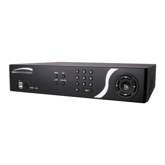
4- & 8-Channel Digital Video Recorder Chapter 3 ─ Configuration NOTE: Your DVR should be completely installed before proceeding. Refer to Chapter 2 ─ Installation. Front Panel Controls Figure 3 ─ DVR front panel. Menu Button Copy Button Esc Button Play/Stop Button Camera Buttons Arrow Buttons... -
Page 18: Copy Button
Operation Instruction Copy Button Pressing the button allows you to copy video clips. COPY Esc Button During menu setup, pressing the button closes the current menu or setup dialog box. Play/Stop Button Pressing the button enters the playback mode, and pressing the button again exits the PLAY/STOP playback mode. -
Page 19: Power Led
4- & 8-Channel Digital Video Recorder Power LED The POWER LED is lit when the unit is On. USB Port A USB port on the front panel is provided to connect external hard disk or flash drives for video clip copying or system upgrades. Position external drives close enough to the DVR so that you can make the cable connections, usually less than 6 feet. -
Page 20: Id Button
Operation Instruction ID Button If a DVR System ID is set to 0, the infrared remote control will control that DVR without any additional operations. (Refer to the System Information setup screen in this chapter for further information on setting the System ID.) If the system ID is 1 to 16, you must to press the button and then press the number button (1 to 16 (+10 &... -
Page 21: Alarm Button
4- & 8-Channel Digital Video Recorder Stop: Pressing the button stops playback and enters the Live Monitoring mode. Backward: When in the pause mode, pressing the button moves to the previous image. Forward: When in the pause mode, pressing the button moves to the next image. -
Page 22: Play/Stop Button
Operation Instruction Play/Stop Button Pressing the button enters the playback mode, and pressing the button again exits PLAY/STOP the playback mode. When entering the playback mode, video is paused. Pressing the button plays back video at regular speed. The screen displays when the DVR is in the Pause mode and the screen displays when the DVR is playing back video. -
Page 23: Setup Screen
4- & 8-Channel Digital Video Recorder NOTE: To log the user out of the system, press the button on the front panel or move MENU the mouse pointer to the top of the screen and then select (Logout) in the Live Monitoring menu. -
Page 24: System Setup
Operation Instruction System Setup Figure 8 ─ System menu. Information Highlight Information in the System menu and press the button. The Information setup screen appears. In the Information screen, you can name the site location, assign a System ID number, select the language the screens are displayed in, display software version number, upgrade the software, show the System Log, display recorded time... - Page 25 4- & 8-Channel Digital Video Recorder Highlighting the Install button and pressing the button will install the selected software package. Highlighting the Cancel button and pressing the button will close the window without upgrading the software. If the upgrade package file is not installed on the DVR properly, you will get an error message.
-
Page 26: Date/Time
Operation Instruction Highlight the box beside File name and press the button. A virtual keyboard allows you to enter the file name. Selecting Export will save the log information in .txt file format on the USB device. NOTE: When opening the saved .txt file, setting to the proper character encoding and using fixed width fonts will be required to read the file properly. -
Page 27: Storage
4- & 8-Channel Digital Video Recorder Highlight the Holiday tab, and the Holiday setup screen appears. You can set up holidays by highlighting + and pressing the button. The current date appears. Highlight the month and day and change them by using the Up and Down arrow buttons. -
Page 28: Figure 13 ─ Storage Information Setup Screen
Operation Instruction The information in the Type column describes the storage device. The capacity of the storage device is displayed in the Capacity column. The Format column displays whether the device is used for recording (Record) or not (Not Using). Not formatted indicates the device is not formatted. -
Page 29: User
4- & 8-Channel Digital Video Recorder The Type column displays the type of storage device. The Disk Bad column displays the percentage of bad sectors. Not formatted – The device is not formatted. Good – Less than user-defined percentage of bad ... - Page 30 System Time Change – The user can change the system date and time on a local system or a PC running Speco Central. Data Clear – The user can clear all video data or format disks on a local system or a PC running Speco Central.
-
Page 31: Ez Setup
4- & 8-Channel Digital Video Recorder PTZ Setup – The user can establish all PTZ settings on a local system or a PC running Speco Central. Alarm-Out Setup – The user can establish all Alarm-Out settings on a local system or a PC running Speco Central. -
Page 32: Figure 17 ─ Ez Record Screen
Operation Instruction If you selected the EZ Record, selecting the Next button starts the EZ Record. Figure 17 ─ EZ Record screen. Date/Time Setup Date: Set the system date and select the date format. Time: Set the system time and select the time ... -
Page 33: Figure 18 ─ Ez Network Screen
4- & 8-Channel Digital Video Recorder NOTE: The recording resolution will be set to Very High when selecting High Video Quality Priority Profile, High when selecting Standard Recording Profile, and Standard when selecting Longer Recording Time Priority Profile. NOTE: The recording quality and recording speed of each camera channel will be set as shown below according to the Record Method and Record Video Quality you set. - Page 34 Operation Instruction LAN Setup Select between Auto Configuration and Manual Configuration for network configuration, and then select the Test button to test the network configuration you selected. NOTE: Selecting Auto Configuration allows the DVR to automatically obtain LAN parameters (IP address, Gateway, Subnet Mask and DNS Server address).
-
Page 35: Shutdown
4- & 8-Channel Digital Video Recorder Select the Finish button to finish the EZ Setup. Shutdown Highlight Shutdown in the System menu and press the button. The Shutdown screen displays asking you to confirm whether or not you want to shut the system down. After selecting Shutdown and pressing the button, a screen will appear telling you when it is safe to disconnect power. - Page 36 Operation Instruction NOTE: The total ips of all camera channels will be limited to 120 ips (60 ips for 4-ch Model) when set to High resolution and 60 ips (30 ips for 4-ch Model) when set to Very High resolution. NOTE: When set to High or Very High resolution, the maximum recording speed of each camera channel might decrease so as not to exceed the total ips of all camera channels.
-
Page 37: Schedule
4- & 8-Channel Digital Video Recorder Highlighting Use Panic Recording and pressing the button toggles between On and Off. Highlight the Panic Recording – Duration box and set the duration of panic recording. Panic recording will stop automatically after the preset duration as long as (Panic) in the Live Monitoring menu is not selected to stop the panic... -
Page 38: Figure 24 ─ Schedule - Settings (Advanced Mode) Setup Screen
Operation Instruction Highlight the Schedule Mode box and press the button. You can select between Simple Mode and Advanced Mode. Selecting Advanced Mode allows you to set up individual recording schedule for each event. Highlight the + and press the button to add a schedule item. -
Page 39: Pre-Event
4- & 8-Channel Digital Video Recorder NOTE: Day, Range and Channels that are not defined will use the setting values of the previous schedule item. NOTE: When more than two schedule items are registered in the same day and time range, the DVR will follow the latest registered schedule item. -
Page 40: Event Setup
Operation Instruction NOTE: When the DVR is in the Time or Time & Event mode, it ignores the pre-event settings and follows the time settings. Event Setup Figure 26 ─ Event menu. Alarm Highlight Alarm-In in the Event menu and press the button. -
Page 41: Figure 28 ─ Alarm-In Actions 1 Setup Screen
NOTE: For the Notify action, the notify item you select should be enabled in the Notification setup screen and the DVR should be registered in the Speco Central (Remote Administration System). Highlight the desired box under the PTZ heading, and press the button. -
Page 42: Motion Detection
Operation Instruction Motion Detection Highlight Motion Detection in the Event menu and press the button. The Motion Detection setup screen appears. Your DVR has built-in video motion detection. Video motion detection can be turned On or Off for each camera. Figure 30 ─... -
Page 43: Figure 31 ─ Motion Detection Actions 1 Setup Screen
4- & 8-Channel Digital Video Recorder You can adjust the minimum number of detection blocks that must be activated to trigger a motion alarm. Highlighting the box under the Min. Blocks heading and pressing the button allows you to adjust the minimum number of detection blocks for Daytime and Nighttime independently. -
Page 44: Video Loss
NOTE: For the Notify action, the notify item you select should be enabled in the Notification setup screen and the DVR should be registered in the Speco Central (Remote Administration System). Highlight the desired box under the PTZ heading, and press the button. -
Page 45: Video Blind
NOTE: For the Notify action, the notify item you select should be enabled in the Notification setup screen and the DVR should be registered in the Speco Central (Remote Administration System). Highlight the desired box under the PTZ heading, and press the button. -
Page 46: Figure 35 ─ Video Blind Settings Setup Screen
Operation Instruction The DVR checks to see if anything is blinding the camera. Figure 35 ─ Video Blind Settings setup screen. Highlighting the box under the Sensitivity heading allows you to adjust the DVR’s sensitivity to video blind for Black and White independently from 0 (Never) and 1 (least sensitive) to 15 (most sensitive). -
Page 47: Text-In
NOTE: For the Notify action, the notify item you select should be enabled in the Notification setup screen and the DVR should be registered in the Speco Central (Remote Administration System). Highlight the desired box under the PTZ heading, and press the button. - Page 48 Operation Instruction Highlight Setup…, and press the button. Use the ATM or POS manufacturer’s recommended settings when configuring the RS232, RS485, USB-Serial or LAN ports. Highlight the box beside Text-In Product, and press the button. Select your device from the list. NOTE: The following description is for a Generic Text Device.
-
Page 49: System Event
NOTE: For the Notify action, the notify item you select should be enabled in the Notification setup screen and the DVR should be registered in the Speco Central (Remote Administration System). Highlight the desired box under the PTZ heading, and press the button. -
Page 50: Figure 40 ─ Health Check Setup Screen
Operation Instruction The DVR can be configured to run self- diagnostics and report the results. Highlighting the box beside System and pressing the button allows you to select the interval that you want the DVR to run self- diagnostics on the system. You can select from 1 hr. -
Page 51: Event Status
Highlight OK and press the button to accept your changes. NOTE: For the Notify action to work, the DVR should be registered in the Speco Central (Remote Administration System). Event Status Highlight Event Status in the Event menu and press the button. -
Page 52: Network Setup
Operation Instruction The Event Status screen displays the status of the DVR’s systems and inputs. Events will be highlighted, and related channels or events will flicker for five seconds when detected. Alarm-In, Motion, Video Loss, Video Blind and Text-In will be highlighted when each event is detected based on the settings you made in the Alarm-In, Motion Detection, Video Loss, Video Blind and Text-In setup screen on the Event... -
Page 53: Figure 45 ─ Network Setup Screen
Central. Highlighting the box beside Remote Audio Channel and pressing the button allows you to select the audio channel that sends audio to the remote site. Selecting Select From Speco Central will send audio of the channel selected from Speco Central. -
Page 54: Figure 46 ─ Lan (Manual) Setup Screen
10019 Remote Audio: 8116 NOTE: You will need to get the appropriate Port Numbers for each Speco Central and Speco Remote related program (Admin, Callback, Watch, Search and Audio) from your network administrator. NOTE: Do NOT use the same port number for two different programs, otherwise, the DVR... -
Page 55: Figure 47 ─ Dvrns Setup Screen
4- & 8-Channel Digital Video Recorder CAUTION: When changing the port settings, you must change the port settings on the PC running Speco Central as well. Refer to the Speco Central Operation Instruction for details. Selecting DHCP from the Type and highlighting... -
Page 56: Figure 48 ─ Rtsp Setup Screen
Operation Instruction NOTE: You will need to get the IP Address or domain name of the DVRNS Server from your network administrator. NOTE: You can use the domain name instead of IP address if you already set up the DNS Server when setting up the LAN. -
Page 57: Notification
NOTE: Selecting Use Mobile sets the remote watch quality to Basic automatically regardless of your Network – Remote Watch settings. NOTE: Selecting Use Mobile sets the Speco Remote service to be enabled automatically regardless of your Speco Remote settings. NOTE: You can access a remote DVR and monitor live video images using media players, such as VLC Player, supporting RTSP service. -
Page 58: Figure 51 ─ Notification Mail Setup Screen
Operation Instruction Highlight the box beside Retry and enter the number of times you would like the DVR to try contacting the computer. You can select from 1 to 10 retries. Highlight the Mail tab, and the Mail setup screen displays. The DVR can be set up to send an email when an event occurs. -
Page 59: Figure 52 ─ Notification Sns Setup Screen
4- & 8-Channel Digital Video Recorder Highlight the box beside Port and press the button. Use the arrow buttons to enter the SMTP Server port number obtained from your system administrator. The default port number is 25. Highlight Enable SSL/TLS and press the button to toggle between On and Off. -
Page 60: Devices Setup
NOTE: For the Notify action, the notify item you select should be enabled in the Notification setup screen and the DVR should be registered in the Speco Central (Remote Administration System. Highlight the box beside Summary Email Interval and select the interval that you want the DVR to send a summary email. -
Page 61: Figure 55 ─ Camera Setup Screen
4- & 8-Channel Digital Video Recorder You can turn the camera number On or Off, and you can change the Title of each camera using the virtual keyboard. You can also determine which cameras will display on the monitors by selecting Normal, Covert 1 or Covert 2 from a drop-down list in the Use column. -
Page 62: Audio
Operation Instruction Configure the port’s setting based on the PTZ camera manufacturer’s instructions. Audio Highlight Audio in the Devices menu and press the button. The Audio setup screen appears. The DVR can record up to four audio inputs. Highlight the box beside the input and press the button. -
Page 63: Digital Deterrent
4- & 8-Channel Digital Video Recorder You can add and edit alarm output schedules on this screen. Highlight the + and press the button to add a schedule. Highlighting the boxes under the Column heading and pressing button allows you to edit the information in those boxes. - Page 64 Operation Instruction You can select the audio files associate with each event. Highlight the box under the Associated Audio and press the button. A list of audio file name appears, and you can select which audio file you want to associated with that event. You can import saved audio files or export the current audio files.
-
Page 65: Display
Ethernet. The icon displays when audio communication is available between the DVR and a PC running Speco Central via Ethernet. Freeze & Sequence – The icon displays while in the Freeze mode, and the displays while in the Sequence mode. -
Page 66: Figure 62 ─ Main Monitor Setup Screen
Operation Instruction Highlight the box beside Mode and press the button. You can select between Full Sequence and Cameo Sequence. (8-ch Model Only) Selecting (Sequence) in the Live Monitoring menu causes the DVR to sequence cameras, and the DVR can sequence cameras in two modes: “Full”... -
Page 67: Remote Control
4- & 8-Channel Digital Video Recorder Highlighting OK and pressing the button applies resolution changes. Remote Control Highlight Remote Control in the Devices menu and press the button. The Remote Control setup screen allows you to select a port and make correct settings for a remote keyboard. Highlight the box beside Port and select between None, RS232 and RS485. - Page 68 Operation Instruction...
-
Page 69: Chapter 4 ─ Operation
4- & 8-Channel Digital Video Recorder Chapter 4 ─ Operation NOTE: This chapter assumes your DVR has been installed and configured. If it has not, please refer to Chapters 2 and 3. The DVR’s controls are similar to a VCR. As with a VCR, the main functions are recording and playing back video. -
Page 70: Live Monitoring Menu
Operation Instruction NOTE: The Live Monitoring menu also can be displayed by moving the mouse pointer to the top of the screen. Live Monitoring Menu Display Selecting (Display Menu) in the Live Monitoring menu displays the following Display Menu. Camera: Selecting Camera and choosing the camera number displays the ... -
Page 71: Camera Menu
4- & 8-Channel Digital Video Recorder Sequence Selecting (Sequence) in the Live Monitoring menu causes the cameras to display sequentially. When in one of the multiview formats, selecting Sequence will cause the DVR to go through predefined screen layouts (Full Sequence). Or, the bottom, right screen will display live cameras sequentially (Cameo Sequence). -
Page 72: Active Cameo Mode
Operation Instruction Digital Deterrent Selecting (Digital Deterrent) in the Live Monitoring menu displays the following setup screen and allows the DVR to play manually. Highlight the box beside Source name and press the button to select the source file to play. Highlighting Trigger plays the selected file as the digital deterrent. -
Page 73: Zoom Mode
4- & 8-Channel Digital Video Recorder Zoom Mode (Camera Menu) Zoom in the Live You can enlarge an area of the video by selecting (Camera Menu) Zoom from the Camera, Monitoring menu. For a few seconds after selecting a rectangle displays on the screen. -
Page 74: Figure 66 ─ Ptz Select Camera Menu
Operation Instruction Select the PTZ camera you wish to control. The icon flickers on the PTZ camera screen. To use the remote control buttons, press the Left and Right arrow buttons to pan left and right. Press the Up and Down arrow buttons to tilt the camera up and down. -
Page 75: Recording Video
4- & 8-Channel Digital Video Recorder Recording Video Once you have installed the DVR following the instructions in Chapter 2 ─ Installation, it is ready to record. The DVR will start recording based on the settings you made in the Record setup screen. See Chapter3 ─... -
Page 76: Searching Video
Operation Instruction Camera Buttons: Pressing the individual camera buttons will cause the selected camera to display full screen. Arrow Buttons: Pressing the button plays video backward at high speed. Pressing the button again toggles the playback speed from . Pressing the button plays video forward at high speed. -
Page 77: Search Menu
4- & 8-Channel Digital Video Recorder NOTE: The Search menu also can be displayed by moving the mouse pointer to the top of the screen. Search Menu Display Selecting (Display Menu) in the Search menu displays the following Display Menu. Camera: Selecting Camera and choosing the camera number displays the ... - Page 78 Operation Instruction Export Selecting (Export) in the Search menu displays the following Export menu. See the following Clip Copy section for details. EZ Copy: Selecting EZ Copy will set the starting point of the video to be clip copied, and the icon displays at the bottom-left corner of the screen.
-
Page 79: Event Log Search
4- & 8-Channel Digital Video Recorder Panic Selecting (Panic) in the Search menu starts panic recording of all cameras, and selecting again stops panic recording. Data Source Selecting (Data Source) in the Search menu allows you to select the data source to be searched. Selecting Record searches recorded data on primary storage installed in the DVR, and selecting Other searches recorded data on storage used for another DVR then installed in this DVR. - Page 80 Operation Instruction Highlight the box beside To and press the button to toggle between On and Off. When set to Off, you can enter a specific Date and Time. When set to On, the search will be to the last recorded image.
-
Page 81: Record Table Search
4- & 8-Channel Digital Video Recorder Record Table Search Recording information about video images currently displayed on the screen displays on < Compact View > the recording status bar. A grey vertical line indicates the current search position. To search specific video, move the vertical line by using the Left or Right arrow buttons on the front <... -
Page 82: Motion Search
Operation Instruction Selecting located at the bottom displays the Search menu. Go to: Displays the first or last recorded image, or searches by date and time (see the previous Searching Video – Go To section of this chapter for more details). Clip-Copy: Clips a video segment and saves it (see the following Clip ... - Page 83 4- & 8-Channel Digital Video Recorder You can search video from the first to last recorded images, or you can set the start and stop times and dates. Highlight the box beside From and press the button to toggle between On and Off. When set to Off, you can enter a specific Date and Time.
-
Page 84: Text-In Search
Operation Instruction Text-In Search The DVR maintains a log of each time there is Text Input. The Text-In Search screen displays this list. Use the arrow buttons to highlight the event for which you would like to see video. Pressing the (Play/Pause) button will extract the video associated with the Text Input and display the first image of the event. -
Page 85: Clip-Copy
4- & 8-Channel Digital Video Recorder Highlighting the + and pressing the button allows you to add a new set of search parameter. Set up the desired search parameter. Refer to the Appendix – Text-In Search Examples for further information on setting up search parameters. The column can be used to delete a set of search parameter or entire sets of search parameters. - Page 86 You do not need to install any special software on your personal computer to review the video clips. Refer to the Speco Central Operation Instruction for instructions on how to review video clips you have copied. NOTE: During Clip Copy, you cannot shut the system down, clear data on the storage device, or format the storage device.
-
Page 87: Appendix
4- & 8-Channel Digital Video Recorder Appendix USB Hard Disk Drive Preparation Preparing the USB hard disk drive in Windows 2000 NOTE: Preparing a USB hard disk drive under Windows XP, Windows Vista and Windows 7 is almost identical to Windows 2000. 1. -
Page 88: Text-In Search Examples
Operation Instruction 12. Right click the newly created hard disk drive icon and select “Format”. 13. In the Format Screen, select “Full” as the “Format type” and click “Start”. 14. After formatting is complete, connect the USB hard disk drive to the DVR. Text-In Search Examples Search Example I 123456789012345678901234567890123456789012345678901234567890... -
Page 89: Search Example Ii
$8, the following search condition can be set. Speco Remote Speco Remote allows you to access a remote DVR, monitor live video images and search recorded video using Internet Explorer web browser anytime from virtually anywhere. - Page 90 Internet Explorer: Version 6.0 or later Start Internet Explorer on your local PC. You can run the Speco Remote program by entering the following information in the address field. “http://IP address:port number” (The DVR IP address and the Speco Remote port number –...
-
Page 91: Web Monitoring Mode
① Click the to access to the web search mode. ② Position the mouse pointer on the WebWatch logo to see the version of the Speco Remote ③ program. The DVR information window displays the login information of Speco Remote. -
Page 92: Web Search Mode
NOTE: The icon will display on each camera screen when audio communication is available between the Speco Remote system and a DVR. Web Search Mode Remote Search is a remote web search program that allows you to search recorded video on the remote DVR. - Page 93 Click the to access to the web monitoring mode. ② Position the mouse pointer on the WebSearch logo to see the version of the Speco Remote ③ program. The DVR information window displays the time information of recorded data on the remote ④...
-
Page 94: System Log Notices
Operation Instruction Click the to save any video clip of recorded data as an executable file, or click the to save ⑪ the current image in a bitmap or JPEG file format. Click the to print the current image on a printer connected to your computer. -
Page 95: Error Code Notices
4- & 8-Channel Digital Video Recorder Error Code Notices System Upgrade Related Clip Copy Related Description Description Unknown error. Unknown error. File version error. Device error. Operating system version error. Mounting failed. Software version error. No media. Kernel version error. Invalid media. -
Page 96: Map Of Screens
Operation Instruction Map of Screens... -
Page 97: Specifications
4- & 8-Channel Digital Video Recorder Specifications VIDEO Signal Format NTSC or PAL (Auto Detect) Video Input Composite: 4 or 8 inputs, 1 Vp-p, auto-terminating, 75 Ohms Composite: 1 BNC, 1 Vp-p, 75 Ohms Monitor Outputs VGA: 1 (Auto Detect) Composite: 720x480 (NTSC), 720x576 (PAL) Video Resolution VGA: 800x600, 1024x768, 1280x1024@60Hz... - Page 98 Operation Instruction GENERAL Dimensions (W x H x D) 10.4" x 2.0" x 7.5" (265mm x 52mm x 191mm) Unit Weight 3.7 lbs. (1.7kg) Shipping Weight 7.3 lbs. (3.3kg) Shipping Dimensions 14.0" x 4.1" x 13.4" (355mm x 103mm x 340mm) (W x H x D) Operating Temperature 41°F to 104°F (5°C to 40°C) Operating Humidity...