Table of Contents
Advertisement
Operator's
Manual
I I:RAFTSMAN°I
12.0 Amp, Variable Speed
2 Peak HP Router Combo
With Fixed Base and Plunge Base
Model No. 320.27683
WARNING:
To reduce the risk of
injury, the user must read and
understand
the Operator's
manual
before using this product.
• WARRANTY
• SAFETY
• UNPACKING
• DESCRIPTION
• OPERATION
• MAINTENANCE
• TROUBLESHOOTING
• ESPANOL
Sears Brands Management
Corporation,
Hoffman
Estates,
IL 60179
U.S.A.
www.craftsman.com
Advertisement
Table of Contents

Related Manuals for Craftsman 320.27683


Summary of Contents for Craftsman 320.27683
- Page 1 • DESCRIPTION WARNING: To reduce the risk of • OPERATION • MAINTENANCE injury, the user must read and • TROUBLESHOOTING understand the Operator's manual • ESPANOL before using this product. Sears Brands Management Corporation, Hoffman Estates, IL 60179 U.S.A. www.craftsman.com...
- Page 2 View and Part List page 33-37 Sears Repair Parts Phone Number Back Cover CRAFTSMAN ONE YEAR LIMITED WARRANTY FOR ONE YEAR from the date of purchase, this product is warranted against any defects in material or workmanship. With proof of purchase, defective product will be replaced free of charge.
- Page 3 The purpose of safety symbols is to attract your attention to possible dangers. The safety symbols and the explanations with them deserve your careful attention and understanding. The symbol warnings do not, by themselves, eliminate any danger. The instructions and warnings they give are no substitutes for proper accident prevention...
- Page 4 SAVE THESE INSTRUCTIONS Some of these following symbols may be used on this tool. Please study them and learn their meaning. Proper interpretation of these symbols will allow you to operate the tool better and more safely. SYMBOL NAME DESIGNATION/EXPLANATION Volts Voltage Amperes...
- Page 5 GENERAL POWER TOOL SAFETY WARNINGS WARNING: Read all safety warnings and instructions. Failure to follow the warnings and instructions may result in electric shock, fire and/or serious injury. • Know your power tool. Read the operator's manual carefully. Learn the applications, as well as the specific potential...
- Page 6 PERSONAL SAFETY • Stay alert, watch what you are doing and use common sense when operating a power tool. Do not use the tool while tired or under the influence of drugs, alcohol, or medication. A moment of inattention while operating power tools may result in serious personal injury.
- Page 7 Always check the tool for damaged parts before use. Before further use of the tool, a guard or other part that is damaged should be carefully checked to determine if it will operate properly and perform its intended function. Check for misalignment or binding of moving parts, breakage of parts, and any other condition that may affect the tool's operation.
- Page 8 Use only identical replacement parts when servicing a tool. Follow the instructions in the maintenance section of this manual. Use of unauthorized parts or failure to follow maintenance instructions may create a risk of electric shock or injury. SPECiFiC SAFETY RULES FOR ROUTER •...
- Page 9 To use cutter bits with a larger diameter, install and use a sub-base with a larger opening (sold separately at Sears stores or other Craftsman outlets). • Do not use large router cutter bits for freehand routing. Use of large...
- Page 10 A_, WARNING: Your Router should never be connected to the power source when you are assembling parts, making adjustments, installing or removing bits, cleaning, or when it is not in use. Disconnecting the Router will prevent accidental starting, which could cause serious personal injury. When unpacking the box, do not discard any packing materials...
- Page 11 Plunge Base Vacuum Port for Plunge Base 2 chip shields Vacuum Port for fixed Base _, _, 2 screws (for attaching port to plunge base) 1/4-in.and 1/2-in. Collet/Nut Edge Guide Depth-Adjustment Wrench Collet/Nut Wrench 27683 ManuaLRevised_11-0120 Page 11...
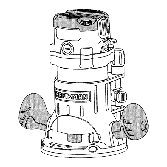
- Page 12 I D] _]_II]_IIIEe]_] KNOW YOUR ROUTER COMBO (Fig.2} NOTE: Before attempting to use your router, familiarize yourself with all of the operating features and safety requirements. Your router has a precision-built electric motor and it should only be connected to a 120-volt, 60-Hz AC power supply (normal household current).
- Page 13 WARNING: Do not allow familiarity with the router to cause a lack of alertness. A fraction of a second of carelessness is enough to cause severe injury. PRODUCT SPECIFICATIONS Rating 12.0 Amps No-Load Speed 10000-25000 RPM Peak HP Input 120V, 60Hz AC Collets/Nuts and Cutter bit Shank 1/4 in.
- Page 14 Protective Plunge Post Bellows protect guideposts from woodchips, dust, and moisture. Spindle Lock for easy 1-wrench bit changes. Includes 1/4 and 1/2-inch Self-Releasing Collets/Nuts for use with a wide variety of 1/4-in. and 1/2-in. router bits, sold separately. 10. 100% Ball Bearings for smooth, efficient operation...
- Page 15 1_1¼inches. To use cutter bits with larger diameters, use sub-bases with larger openings, sold separately at Sears stores or other Craftsman outlets. WARNING: Always turn the motor off and unplug the router before making any adjustments or installing accessories.
- Page 16 Insert the cutter bit shank into the collet/nut Fig. 3a /_<'_A_ \ Cutters assembly as far as it will go, then back the shank out until the cutters are approximately _X_/Bit Shank 1/8 to 1/4 inch away from the face of the "J Spindle collet/nut...
- Page 17 Place the wrench on the collet/nut, and turn it counter-clockwise to loosen collet/nut slightly to accept the cutter bit shank. Insert the cutter bit shank into the collet/nut assembly as far as it will go, then back the shank out until the cutters are approximately 1/8 to 1/4 inch away from the face of the collet/nut (Fig.
- Page 18 CUTTER BITS Get faster, more accurate cutting results by keeping cutter bits clean and sharp. Remove all accumulated pitch and gum from cutter bits after each use. When sharpening cutter bits, sharpen only the inside of the cutting edge. Never grind the outside diameter.
- Page 19 With the motor housing slot (C) aligned with the plunge base pin (D), lower the motor housing into the plunge base, engaging the pin into the slot. Slide the motor into the base as far as it will go. Close the motor clamp securely. REMOVING THE MOTOR FROM THE BASES...
- Page 20 DEPTH ADJUSTMENT WITH FIXED BASE (Figs. 6 and 7) NOTE: All depth adjustments on the fixed base must be made with the motor clamp open. NOTE: For all fixed base routers, the cutter bit depth equals the amount of the cutter that is exposed below the surface of the sub-base.
- Page 21 With the cutter bit already installed, press in the Coarse Adjustment Knob (B) and lower the motor into the base until the cutter bit is very close to the flat surface on which the base is sitting. Turn the Fine Adjustment Dial (C) until the cutter bit "just"...
- Page 22 PLUNGING ACTION (Fig. 8) The plunge base feature simplifies the depth adjustments and allows the cutter bit to be accurately lowered down into the workpiece for more precise set-ups. To lower the cutter bit, release the plunge- lock lever by moving it "Up" to the unlocked position.
- Page 23 To set a desired cutting depth, slide the depth-stop rod up until the red line on the clear plastic depth indicator points to your desired cutting depth on the depth scale (E). Secure the depth-stop rod at this position by tightening the depth-rod locking knob (C).
- Page 24 To use the micro-adjustment knob after the depth rod and turret have been set, check the final depth setting and micro-adjust as follows: • To micro-increase the plunge depth, raise the micro-adjustment screw by turning the knob counterclockwise the desired amount. To micro-reduce the plunge depth, lower the micro-adjustment screw by turning the knob clockwise the desired amount.
- Page 25 "LIVE TOOL INDICATOR" LIGHT (Fig. 13) Fig. 13 Your router also has a "Live Tool Indicator" green light, located on the motor housing top cap where the power cord enters the motor housing. This green light is always on when the router motor is plugged into a power source.
- Page 26 ELECTRONIC VARIABLE SPEED CONTROL (Fig. 16} The electronic speed control feature allows motor speed to be matched to cutter size and Fig. 16 material for an improved finish and extended bit life. Speed changes are made starting at "1" and rotating the Speed Control Dial to the "LEFT"...
- Page 27 The speed charts on the preceding page indicate the relationship between the speed setting and the cutting application. Exact settings are determined through operator experience and preference, and also by recommendations manufacturers of cutter bits. ELECTRONIC FEEDBACK CIRCUITRY The router electronic feedback circuitry monitors...
- Page 28 EDGE ROUTING (Figs. 17 and 17a) Fig. 17a 1. With the depth-of-cut set, place the router on the edge of workpiece, making sure that the cutter does not contact workpiece. (With the plunge base, lock the plunge action in the DOWN position, ready to cut).
- Page 29 When the cut is complete, turn the router motor "OFF" and allow the cutter bit come to a complete stop before removing it from the workpiece. Unplug the router from power source, place the router upside down on the worktable, and inspect the finished cut in the workpiece.
- Page 30 FREEHAND ROUTING WITH THE FIXED BASE (Fig. 21) WARNING: Do not use large cutter bits Fig. 21 for freehand routing. Using large cutter bits when freehand routing could cause loss of control or create other hazardous conditions that could result in personal injury. If using a router table, large bits should be used for _'-- edging only.
- Page 31 Top Edge Shaping Fig. 22a Whenever the workpiece thickness, together with the desired depth of cut (as adjusted router depth setting) are such that only the top part of the edge is to be shaped (leaving at least a 1/16-in. thick uncut portion at the bottom), the pilot can ride against the uncut portion, which serves to guide it (Fig.
- Page 32 possibly resulting in personal injury. When "Climb-Cutting" is required (e.g., backing around a corner), exercise extreme caution to maintain control of the router. The high speed of the cutter bit during a proper feeding operation (left to right), results in very little kickback under normal conditions.
- Page 33 RATE OF FEED (Figs. 25 and 25a) The proper rate of feed depends on several factors: the hardness and moisture content of the workpiece, the depth of cut, and the cutting diameter of the bit. When cutting shallow grooves in soft woods such as pine, you may use a faster rate of feed.
- Page 34 CHIP SHIELDS (Figs. 26 and 26a) _1, WARNING: Always wear eye protection. The chip shields are not intended as safety guards. To remove the chip shield from the fixed base, press inward on the tabs until the chip shield releases from the base and then remove the chip shield.
- Page 35 DUST COLLECTION WITH VACUUM PORT (Figs. 27 and 27a) Two vacuum ports are included with the router bases. Each adapter is sized to accept Fig. 27 a 1-1/4-in. vac hose adapter, sold separately. ATTACH THE VACUUM PORT ONTO THE FIXED BASE (Fig. 27) To attach the vacuum port onto the fixed base, align the two tabs on the port with the...
- Page 36 Fixed Base Router Fig. 28a When using either the fixed base to attach the router to the router table, the bit depth can be adjusted by turning the Micro-adjustment Dial clockwise or counterclockwise with the wrench supplied. (Fig. 28a and Fig. 28b). The depth of the cut can be read on the scale dial.
- Page 37 All other parts represent an important part of the double-insulation system and should be serviced only by a qualified Craftsman service technician. WARNING: For your safety, always turn off the switch and unplug the router motor from the power source before performing any maintenance or cleaning.
- Page 38 REPLACEMENT OF CARBON BRUSHES (Fig .29) Replacement brush sets are Fig. 29 available through Sears Parts and Repair Centers. Unplug the router motor before inspecting replacing brushes. Replace both carbon brushes when either has less than 1/4-in. length of carbon remaining, or if the spring or wire is damaged...
- Page 39 1/2-in. collet. WARNING: The use of attachments or accessories that are not recommended for this tool might be dangerous and could result in serious injury. Sears and other Craftsman outlets offer a large selection of Craftsman router accessories designed for specific routing applications.
- Page 40 1/8-in. 3/8-in. 1/4-in. straight straight straight straight ;,iJ 5/16-in. 1/2-in. 3/4-in. straight straight straight dovetail 3/8-in. dove tail 1/2-in. dove tail round nose 1/2-in. round nose 1/2-in. 90 d v groove v groove 1/2 x 1-in. 3/8x1/2-in. flush trim flush trim flush trim 1/2-in.
- Page 41 1/2-in. bead and cove bead cove 1/16-in. classiccove&bead classic cove with bead 1/4-in. roman ogee Roman ogee 3/8-in. rabbeting rabbeting 1/4-in. veining veining 1/2-in. core box core box 1/2-in. mortising mortising 1/4-in. panel pilot panel pilot 1-3/8-in. 45 ochamfer chamfer 27683 ManuaLRevised_11-0120 Page 41...
- Page 42 12 Amp Router Model No. 320.27683 The Model Number will be found on the Nameplate attached to the motor unit. Always mention the Model Number when ordering parts for this tool. 27683 Manual_Revised_11-0120 Page 42...
- Page 43 12 Amp Router Model No. 320.27683 The Model Number will be found on the Nameplate attached to the motor unit. Always mention the Model Number when ordering parts for this tool. 27683 ManuaLRevised_11-0120 Page 43...
- Page 44 12 Amp Router Model No. 320.27683 The Model Number will be found on the Nameplate attached to the motor unit. Always mention the Model Number when ordering parts for this tool. 27683 ManuaLRevised_11-0120 Page 44...
- Page 45 12 Amp Router Model No. 320.27683 The Model Number will be found on the Nameplate attached to the motor unit. Always mention the Model Number when ordering parts for this tool. 5610220000 Screw 3321133000 Rear Cover 3121518000 Transparent 5610017000 Tapping Screw 4890638000 Speed Adjustor 5620017000...
- Page 46 3421186000 Motor Housing 5700056000 Ball Bearing 5610076000 Tapping Screw 5630179000 3551635000 Spindle Lock 3660174000 Stop Spring 5620061000 Screw 3421190000 Spindle Lock Cover 5620069000 Screw 2823121000 Collet Assembly 5620041000 Screw 3320460000 Adjusting Knob 3123281000 Indicator 3550841000 Shaft 5660005000 "E" Ring 3660498000 Spring 3126054000 Handle Sleeve...
- Page 47 2822272000 Adjusting Assy 5650337000 Washer 5620067000 Screw 5620032000 Screw 3123435000 Adjusting Knob 5650014000 Washer 3660313000 Spring 3550083000 Depth Adjusting Bolt 3550913000 Depth Stop Bar 3121634000 Depth Indicator 3121639000 Cover 5660018000 Circlips 3402338000 Lock Bolt 3123498000 5630016000 3123497000 Cover 2823123000 Plunge Frame 3660254000 Torsion Spring 5640045000...
- Page 48 5620074000 Screw 3402220000 Depth Adjusting Lever 2823125000 Collet Assy 3123454000 Vaccum Adapter 5620353000 Screw 3123500000 Support Plate 3550588000 Guiding 3703925000 Fence 5650013000 Washer 5650015000 Spring Washer 5620050000 Screw 3123344000 Chip Shield 3402471000 Wrench 3123286000 Vaccum Adapter 27683 ManuaLRevised_11-0120 Page 48...
- Page 49 27683 Manual_Revised_11-0120 Page 49...
- Page 50 27683 Manual_Revised_11-0120 Page 50...
- Page 51 27683 Manual_Revised_11-0120 Page 51...
- Page 52 Your Home For troubleshooting, product manuals and expert advice: managemylife www.managemylife.com For repair - in your home - of all major brand appliances, lawn and garden equipment, or heating and cooling systems, no matter who made it, no matter who sold it! For the replacement parts, accessories and owner's manuals that you need to do-it-yourself.