Table of Contents
Advertisement
Available languages
Available languages
Operator's
Manual
P
R
0
F
E
S
S
I
0
N
A
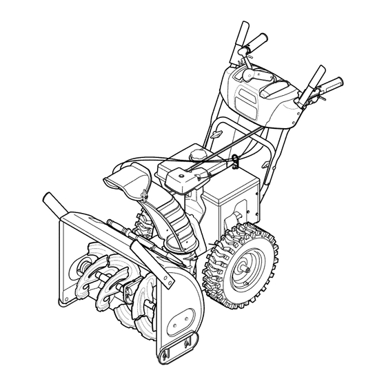
30" SNOW THROWER
Model No. 247.888301
CAUTION:
Before
using
this product,
read this
manual
and follow
all
safety
rules
and operating
instructions.
o SAFETY
ASSEMBLY
OPERATION
MAINTENANCE
PARTS LIST
o ESPANOL
Sears Brands
Management
Corporation,
Hoffman
Estates,
IL 60179, U.S.A.
Visit our website:
www.craftsman.com
FORM1/O.769-05137E
7/26/2011
Advertisement
Table of Contents

Related Manuals for Craftsman 247.888301


Summary of Contents for Craftsman 247.888301
- Page 1 Model No. 247.888301 o SAFETY ASSEMBLY OPERATION MAINTENANCE PARTS LIST CAUTION: Before using o ESPANOL this product, read this manual and follow safety rules and operating instructions. Sears Brands Management Corporation, Hoffman Estates, IL 60179, U.S.A. Visit our website: www.craftsman.com FORM1/O.769-05137E 7/26/2011...
- Page 2 This warrantyappliesfor onlyone yearfromthe dateof purchaseif this productis everusedwhileprovidingcommercialservicesor if rentedto anotherperson. Forwarranty coveragedetails to obtain repairor replacement, visit the web site: www.craftsman.com This warrantycovers ONLYdefects in material and workmanship. W arranty coverage does not include: •...
- Page 3 This machinewas builtto be operatedaccordingto the safeopera- This symbolpointsout importantsafetyinstructionswhich,if not tion practicesin this manual.As with anytype of powerequipment, followed,couldendangerthepersonalsafetyand/orpropertyof carelessnessor error on the partof the operatorcan resultin serious yourselfand others. Readand followall instructionsin this manual injury.This machineis capableof amputatingfingers,hands,toes beforeattemptingto operatethis machine.Failureto complywith and feet and throwingdebris.Failureto observethe followingsafety these instructionsmay resultin personalinjury.Whenyou seethis...
- Page 4 Safe Handling of Gasoline • Exerciseextremecautionwhenoperatingon or crossinggravel surfaces.Stay alertfor hidden hazardsor traffic. Toavoidpersonalinjuryor propertydamageuseextremecare in handlinggasoline.Gasolineis extremelyflammableand the vaporsare • Exercisecautionwhenchangingdirectionand whileoperatingon explosive.Seriouspersonalinjurycan occurwhengasolineis spilled slopes.Do notoperateon steep slopes. on yourselfor yourclotheswhichcan ignite.Washyour skin and • Planyoursnow-throwing patternto avoiddischargetowards changeclothesimmediately.
- Page 5 MAINTENANCE & STORAGE DO NOT MODIFY ENGINE • Nevertamperwith safetydevices.Checktheirproperoperation Toavoidseriousinjuryor death,do not modifyengine in any way. regularly.Referto the maintenance and adjustmentsectionsof Tampering with the governorsettingcanlead to a runawayengineand this manual. cause it to operateat unsafespeeds.Nevertamperwithfactory setting of engine governor. •...
- Page 6 SAFETY SYMBOLS This pagedepictsand describessafetysymbolsthat mayappear on this product. Read,understand,and followall instructionson the machine beforeattemptingto assembleand operate. READ THE OPERATOR'S MANUAL(S) Read, understand, and follow all instructions in the manual(s) before attempting to assemble operate WARNING-- ROTATING BLADES Keep hands out of inlet and discharge openings while machine is running.
- Page 7 Thispage leftintentionally blank.
- Page 8 NOTE:References to rightor left sideof the snowthrowerare determined from behindthe unit in the operatingposition(standing directlybehindthe snow thrower,facingthe handlepanel). Chute Control Head REMOVING FROM CARTON Cut the cornersof thecarton and lay the sidesflat on the ground. Removeand discard all packinginserts. Movethe snowthrowerout of thecarton. Makecertainthe carton has beencompletelyemptiedbefore discardingit.
- Page 9 Placechuteontochute baseand ensurechutecontrol rod is positionedunder handlepanel.Installhex boltpreviouslyremoved TopView but do notsecurewith wing nutat this time.See Figure4. Squeezethetriggeron the handlepaneljoystickand rotatethe chute byhand to face forward.The holesin the chutecontrol inputwill be facing up. See Figure5. NOTE:The chutewill not rotatewithoutsqueezing the triggeron the joystick.
- Page 10 Makesureall cables are routedto the left of the chutecontrol rod. Line up the hole in thechute control rodwith the arrowon the input shaftand insertthe rod intothe inputshaft belowjoystickon handle panel.See Figure7. NOTE:Thechute controlrod will fit snugglyintothe inputshaft. Supportthe rear of thedash panelwith one handwhileinsertingthe rod with yourotherhandto ensurethe rod is insertedall the way into the input shaft.
- Page 11 10. Checkthat all cables are properlyroutedthroughthecable guide "_ on theengine.See Figure10. NOTE: if the chutecontrol is notassembledcorrectlyit will not move freelynor will it movefully to the rightand left. 11. Theextensioncord forthe electricstarteris fastenedwith a cabletie to the rearof the auger housingfor shippingpurposes. Cutthe cabletie and removecord beforeoperatingthe unit.
- Page 12 Chute Clean-Out Tool A chute clean-out tool is fastenedto the top of the augerhousing with a mountingclip. See Figure12.The tool is designedto cleara chuteassemblyof ice and snow.This item is fastenedwith a cabletie at the factory.Cut thecable tie beforeoperatingthe snowthrower. Chutedean-out Tool loft _1 .allmovingpartshave stoppedbeforeusingthe clean-outtool to clearthe chuteassembly.
- Page 13 Use a middleor lowerpositionwhenthearea to be clearedis uneven,such as a graveldriveway. NOTE:If you chooseto operatethe snowthroweron a gravelsurface, keepthe skid shoesin positionfor maximumclearancebetweenthe groundand the shaveplate. Operatinga snowthrowerequippedwith steelskid shoes may result in damageto naturalstonepaversurfaces(e.g.sandstone,blue- stone,limestone). Forinformationon availablepolymerskid shoes, call 1-800-4MY-HOME. Toadjustthe skid shoes: Loosenthe fourhex nuts (two on each side)and carriagebolts.
- Page 14 Shift Lever Drive Control Four-Way Chute ControP (Joystick) Headlight //_ ....AugerControl. Gas Cap Chute Assembly \\\\\ Drift Cutter Muffler Handle Oil Fill Primer Choke Augers Skid Shoe Oil Drain Figure15 Nowthat youhaveset up yoursnowthrower,it'simportant to become acquainted with its controlsand features.Referto Figure15. The key is a safetydevice.It mustbe fully insertedin order for the engineto start.
- Page 15 THROTTLE CONTROL The augercontrol is locatedon the left handle.Squeezethe control grip againstthe handleto engagethe augerand startsnowthrowing action.Releaseto stop. DRIVE CONTROL/AUGER CONTROL LOCK Thethrottlecontrolis locatedon the rearof the engine.It regulatesthe DRIVE speedof theengine and will shutoff the enginewhenmovedintothe CONTROL STOPposition. ELECTRIC STARTER BUTTON Pressingthe electricstarterbuttonengagesthe engine'selectric...
- Page 16 CLEAN-OUT TOOL • Refuelin a well-ventilated area with the enginestopped.Do not smokeor allowflamesor sparksin the areawherethe engineis refueledor wheregasolineisstored. • Donot overfillthe fueltank.After refueling,makesurethe tank Neveruseyourhandsto cleara cloggedchuteassembly.Shut cap is closed properlyand securely. loft engineand remainbehindhandlesuntil all movingparts have • Be carefulnotto spillfuel whenrefueling.Spilledfuel or fuel vapor lstopped beforeusingtheclean-outtool to clearthe chuteassembly.
- Page 17 TO ENGAGE DRIVE Movethrottlecontrolto FAST(rabbit)'_ position. With the throttlecontrolin the Fast(rabbit) position,moveshift Movechoketo the CHOKE IJl position(coldenginestart). If leverinto one of the six forward(F) positionsor two reverse(R) engineis warm,placechokein RUNposition. positions.Selecta speedappropriatefor the snowconditionsand Pushprimerthree (3) times, makingsureto covervent hole in a paceyou'recomfortable with.
- Page 18 MAINTENANCE SCHEDULE Before performing anytype ofmaintenance/service, disengage all Followthe maintenance schedulegiven below.This chart describes controls and stoptheengine. W aituntilall moving partshavecometo serviceguidelinesonly. Usethe ServiceLog columnto keeptrackof a completestop.Disconnect sparkplugwireandgroundit against t he completedmaintenance tasks.To locate the nearest Sears Service enginetoprevent u nintended starting. A lwayswearsafety glassesduring Centeror to scheduleservice,simplycontactSearsat 1-800-4-MY-HOME®.
- Page 19 Reinstallthe drain plugand tightenit securely. Refillwith the recommended oil and checkthe oil level.See Recommended Oil Usagechart.Theengine'soil capacityis 37 ounces. (%-40 °-20 o 0o 200 400 Oil Drain ("c) -300 -200 -10° 0° Plug DO NOTuse nondetergent o il or 2-strokeengineoil. It could shorten the engine'sservicelife.
- Page 20 hot a nd can ine. LUBRICATION Gear Shaft Thegear (hex)shaft shouldbe lubricatedat least oncea seasonor afterevery 25 hoursof operation. Topreventspillage,removeall fuel fromtank by runningengine until it stops. Carefullypivotthe snowthrowerup and forwardso that it restson theauger housing. "?X Removethe lowerframecover fromthe undersideof the snow / ..
- Page 21 ADJUSTMENTS Shift Cable If thefull rangeof speeds(forwardand reverse)cannotbe achieved, referto the figureto the rightand adjustthe shift cableas follows: Placethe shiftleverin thefastest forward speedposition(F6). Loosenthe hex nuton the shiftcable indexbracket.See Figure Pivotthe bracketdownwardto take up slack in the cable. Retightenthehex nut. Drive Control Whenthedrivecontrol is releasedand in thedisengaged"up"position, the cableshouldhavevery little slack.It shouldNOTbe tight.
- Page 22 Auger Control "_ Referto the Assemblysectionfor instructions on adjustingtheauger controlcable. Skid Shoes Referto the Assemblysectionfor instructions on adjustingthe skid shoes. BELT REPLACEMENT Auger Belt To removeand replaceyoursnow thrower'sauger belt, proceedas follows: Topreventspillage,removeall fuel fromtank by runningengine until itstops. Removethe plasticbelt coveron the front of the engineby remov- Figure27 ing the two self-tappingscrews.See Figure27.
- Page 23 7. Remove the belt f rom around the auger pulley, and slip the belt between thesupport bracket and the auger pulley. See Figure 31. 8. Reassemble auger belt b yfollowing these i nstructions inopposite order and manner ofremoval. 9. Perform t he Auger Control test o utlined inthe Assembly section ofthis manual.
- Page 24 If the snowthrowerwillnot be usedfor30 daysor longer,or if it is the end of the snowseasonwhenthe last possibilityof snowis gone,the equipmentneedsto be storedproperly.Followstorageinstructionsbelowto ensuretop performance from the snowthrowerfor manymoreyears. PREPARING SNOW THROWER PREPARING ENGINE Whenstoringthe snowthrowerin an unventilatedor metal stor- Enginesstoredover30 days need to be drainedof fuel to prevent age shed,careshouldbe taken to rustprooftheequipment.Using deterioration and gumfrom formingin fuel systemor on essential a light oil or silicone,coat theequipment,especiallyanychains,...
- Page 25 Enginefails to start Chokecontrolnot in CHOKEposition. Movechokecontrolto CHOKEposition. Sparkplugwire disconnected. Connectwireto sparkplug. Faultysparkplug. Clean,adjustgap,or replace. Fueltank emptyor stalefuel. Filltank with clean,freshgasoline. Enginenot primed. Primeengineas instructedin the OperationSection. Keynot inserted. Insertkeyfully intothe switch. Connectone end of the extensioncordto the electric Extensioncordnot connected(when usingelectricstartbutton,on modelsso starteroutletand the otherend to a three-prong equipped).
- Page 26 Craftsman Snow Thrower IViodel 247.888301 i27j...
- Page 27 Craftsman Snow Thrower IViodel 247.888301 731-2635 SnowRemoval T oolMount 684-04107-4028 Spiral Assembly,LH 684-04108-4028 684-04057A-0637 ImpellerAssembly,12"Dia. Spiral Assembly,RH 731-04870 Spacer,1.25OD x .75ID x 1.00 L710-0347 L Hex Screw,3/8-16, 1.75,Gr5 710-0451 Bolt, Carriage,5/16-18,.750Grl 736-0188 Washer,Flat,.76x 1.49x .06 710-04484 Screw, 5/16-18,0.750 741-0493A Bushing,Flange,.80ID x .91OD...
- Page 28 Craftsman Snow Thrower Model 247.888301 ,,65/, €...
- Page 29 684-04112B HandleEngagement A ssemblyRH 631-04133A HandleClutchLockAssembly- LH 738-04367 FlangeShoulderScrew 684-04111B HandleEngagement A ssemblyLH 731-04894D LockPlate 784-5594-0637 Cable Bracket 684-04250 PivotRod 720-0284 Wing Knob 935-0199A RubberBumper 712-04063 FlangeLock Nut,5/16-18 731-06451 ChuteTilt CableGuide 710-3069 Screw,1/4-20x .500 731-04896B ClutchLock Cam 711-04469A ClevisPin 712-04081A ShoulderNut, 1/4-20 710-04484 Screw,5/16-18x 0.75...
- Page 30 __ 4_ Craftsman Snow Thrower IViodel 247.888301 _.._,=_. _ -'-_, /49_ _" _53) (761...
- Page 31 D_i BO ¸ 710-1652 AB Screw,1/4-20x 0.625 684-04159 FrictionWheelAssembly 731-06401 BeltCover 716-0136 RetainerRing 735-04099 Plug,3/8 ID 726-0221 Speed Nut 711-1268B ActuatorShaft 790-00183B-0637 WheelDrive Frame 746-04229B DriveClutchCable 756-04109 Auger Pulley 736-0505 FiatWasher 732-04345 ExtensionSpring 790-00207B DriveClutchCableGuideBracket 738-04439 ShoulderScrew 936-0119 LockWasher 684-04156A Shift RodAssembly 750-04474 AxleSupportTube...
- Page 32 Craftsman Engine Model 483=SUA For Snow Model 247.888301 710-04968 Bolt,M6x14 951-11339 MufflerShield 710-04915 Bolt M6x12 951-10757 ThrottleControlKnob 951-11595 ControlPanel 951-10637 KeySwitch Base 731-05632 951-11302 ChokeKnob 710-04914 Bolt M6xlO 951-11181 ExhaustPipe Shield 951-11321 CarbIsolatorBracket 710-04968 Bolt M6x16 951-11338 MufflerAssembly 712-04219 Nut M8...
- Page 33 Craftsman Engine IViodel 483-SUA For Snow IViodel 247.888301 _131 ,39- c _jj-u 140-0 0114O 141 / 710-05392 StudM6-8x100 Carburetor IdleSpeedAdjustingScrew 710-05056 StudM6-8x118 Carburetor MixtureScrew 951-11315 CarburetorInsulatorGasket 751-11991 PrimerHose 951-11316 CarburetorInsulator 951-11906 HoseClamp 951-11223 Carburetor Gasket CarburetorBody 951-11303A Carburetor Assembly FloatPin...
- Page 34 Craftsman Engine IViodel 483=SUA For Snow IViodel 247.888301...
- Page 35 Craftsman Engine IViodel 483=SUA For Snow IViodel 247.888301 951-11951 710-04968 Bolt M6x16 ConnectingRodAssembly 951-11952 Piston 951-11320 DipstickClamp 951-11953 710-05349 Bolt M6x8 PistonPin Snap Ring 951-11954 PistonPin 951-11381 Oil FillTubeO-Ring 951-12579 951-11972 PistonRingSet Oil FillTubeAssembly 951-11956 951-11904 GovernorGear/ShaftAssembly DipstickO-Ring 951-11373 951-11971A...
- Page 36 Craftsman Engine Model 483-SUA For Snow Model 247.888301 110_ _I04 120 119 _126a ,126...
- Page 37 Craftsman Engine IViodel 483=SUA For Snow IViodel 247.888301 951-11966 RockerArm 951-11337 ValveKit 751-11123 951-11337 ValveKit AdjustingNut ,Valve 751-11124 951-11962 Nut PivotLocking Tappet 710-05054 ValveCoverBolt 951-11335 PushRod 951-11967 ValveCoverGasket 951-12555 CylinderHeadKit 951-11220 ValveCover (Inc1.106,110-112,125) 951-11221 BreatherHose 715-04097 DowelPin 12x20 126a 726-04101...
- Page 38 Craftsman Engine Model 483=SUA For Snow Model 247.888301 710-04965 Bolt M4x55 951-11313 FanCooling 951-11314 951-11196 Startup Electromotor PulleyStarter 712-04220 710-04967 Bolt M8x55 Nut SpecialM16x1.5 951-11305 710-04968 Bolt M6x16 IgnitionCoilAssembly 710-05350 710-04915 Bolt M6x12 IgnitionCoil Bolt 951-11211 951-11961 CoilAssy.Oharge BlowerHousing 951-11310...
- Page 39 Craftsman Engine Model 483-SUA For Snow Model 247.888301 26 / 951-12532 710-04921 Bolt M8x14 FuelCap Assembly 951-11933 FuelLevelIndicator 951-11182 GasTankSupportBracket 710-04970 BoltM8x20 712-04219 Nut M8 750-05312 BushGasTank 712-04212 Nut M6 750-05313 BushGasTank 710-04908 GovernorArm Bolt 951-11201 951-11307 GovernorArm FuelTankAssembly 951-11319...
- Page 40 Craftsman Engine IViodel 483=SUA For Snow IViodel 247.888301 777S33614 777123018 777123039 777123027 777123017 777122992 SERIALNUMBER CODELABEL EPA LABEL...
- Page 41 Craftsman Snow Thrower IVlodel 247.888301 777S32636 777122339 • [ -- 3001 lnO'NV:Z30 • "WflNVW S,UOIVH3dO QV]H '_ 'S30V_HflS ]3AVH9 NO 9NllPU]dO N3HM NOIlflPO VHIX3 3Sfl '$810NVISt81P 39UVHOSIO 103U10U3fi3N 'S31HflrNI $10]P80 NMOUH1 OlOAV 01 '_ '3NIHOVW 9NIOIAU3S HO 9NIOOO30Nfl 3H0338 O]dd01S ]AVH SlUVd 9NIAOW TIP 311Nil S33QNVH ]NIH38 NIVW]U QNV '3NION] d01S '8_A33 HOlfl]O 39VgN3SIQ'8 "]INH9 39HVHOSIO 90"lONn 013001...
- Page 42 MTD CONSUMER GROUP INC (MTD), the California Air Resources Board (CARB) and the United States Environment Protection Agency (U. S. EPA) Emission Control System Warranty Statement (Owner's Defect Warranty Rights and Obligations) EMISSION CONTROLSYSTEM COVERAGE IS APPLICABLE TOCERTIFIEDENGINESPURCHASED IN CALIFORNIA IN 2005 ANDTHERE- AFTER,WHICHARE USEDIN CALIFORNIA, A NDTO CERTIFIED MODELYEAR2005 AND LATERENGINESWHICHARE PURCHASED AND USEDELSEWHERE IN THE UNITEDSTATES.
- Page 43 (4)Repair orreplacement ofany warranted part under the warranty provisions ofthis article m ust beperformed atnocharge tothe owner ata warranty station. (5)Notwithstanding the provisions ofSubsection (4) above, warranty services orrepairs must beprovided atallMTD distribution centers that are franchised toservice the subject engines. (6)The owner must not b echarged fordiagnostic labor that l eads tothe determination that a warranted...
- Page 44 Look For Relevant Emissions Durability Period and Air index information On Your Engine Emissions Label Engines that are certified to meet the California Air Resources Board (CARB) Tier 2 Emission Standards must display information regarding the Emissions Durability Period and the Air Index. Sears Brands Management Corporation makes this information available to the consumer on our emission...
- Page 45 Congratulations on making a smart purchase. Your new Craftsman® product is designed manufactured for years of dependable operation. But like all products, it may require repair from time to time. That's when having a Repair Protection Agreement can save you money and aggravation.
- Page 46 Almacenamiento fuera de temporada ..Pagina 69 GARANTiA PROFESIONAL TOTAL CRAFTSMAN POR DOS AltOS PORDOSANOSa partir de la fechade cornpra,este productoest&garantizadocontracualquierdefectode materialo rnanode obra.El productodefectuosorecibir_, l a reparaci6no la sustituci6ngratuitasi la reparaci6nno est,. disponible. Estagaranfias61o tiene vigenciapot un aSodesdela fechade cornprasi este productosehan utilizadoalgunavez,rnientrasque la prestaci6n de servicioscornercialeso si se alquilaa otrapersona.
- Page 47 Esta rn_.quina r ue construidapara seroperadade acuerdocon La presenciade este sfrnboloindicaque setrata de instrucciones las reglasde seguridadcontenidasen este manual.AI igualque irnportantesde seguridadque se deben respetarpara evitar concualquiertipo de equipo rnotorizado, u n descuidoo error por poner en peligrosu seguridadpersonaly/o materialy la de otras partedel operadorpuedeproducirlesionesgraves.Esta rn_.quina personas.Lea y siga todaslas instruccionesde este manualantes es capazde arnputarrnanosy piesy de arrojarobjetoscon gran...
- Page 48 Manejo seguro de la gasolina • Nuncaoperela rn_.quina si falta un rnontajedel canalo si el rnisrnoest,. daSado.Mantengatodos losdispositivosde seguri- Paraevitar lesiones personales 0 daSosrnateriales tengarnucho dad en su lugaryen funcionarniento. cuidadocuandotrabajecon gasolina.La gasolinaes surnarnente inflarnabley sus vaporespuedencausarexplosiones. S i se derrarna •...
- Page 49 • Paraencenderel motor,jale de la cuerdalentarnente hasta que • SegOn la Cornisi6nde Seguridad de Productosparael Consurni- sienta resistencia,luegojale r_.pidarnente. El replieguer_.pido de dor de los EstadosUnidos(CPSC)y la Agenciade Protecci6n la cuerdade arranque(tensi6nde retroceso)le jalar_,la rnanoy Arnbiental d e los EstadosUnidos(EPA),este productotieneuna el brazohaciael motor rn_.s r_.pido de Io que usted puedesoltar.
- Page 50 SiMBOLOS DE SEGURIDAD Esta p_ginadescribelossimbolosy figurasde seguridadinternacionales que puedenapareceren este producto.Lea el manualdel operador )araobtenerla informaci6n terminadasobreseguridad,reunirse,operaci6ny mantenimiento y reparaci6n. LEA EL MANUAL DEL OPERADOR (S) Lea, entienda, y siga todas las instrucciones en el manual (es) antes de intentar reunirse y funcionar.
- Page 51 NOTA:las referencias al lado derechoo y ciertosde la rn&quina quitanievese deterrninan desdela parteposteriorde la unidaden posM6n de operaci6n(perrnaneciendo directarnente detr&sde la Cabezal Control del rn&quina quitanieve,rnirandohaciael panelde la rnanija), Canal M_nsula EXTRACCION DE LA UNIDAD DE LA CAJA Corte lasesquinasde la cajade cart6ny exti_ndalaen el piso Quitey descartetodoslos insertos de ernpaque.
- Page 52 4. Ubique elcanal sobre l abase d el m ismo ygarantizar lavarilla h ex agonal est,. situado bajo elpanel manejar. Instalar elperno hexagonal previamente eliminado, pero n oseguro con tuerca de mariposa eneste momento. Vea lafigura 4 . 5. Apriete eldisparador enlapalanca decontrol ygire elcanal manualmente para q ue mire hacia d elante.
- Page 53 7. Inserte la varilla hexagonal dentro del engranaje del pih6n por debajo de la palanca de control. Asegurese de alinear el orificio en la varilla hexagonal con la flecha en el engranaje del piB6n. Vea la figura 7. NOTA:El orificioes una referenciaparaalinear la varillacon la flecha indicadoraen el engranaje del pi56n.
- Page 54 10. Controleque todos loscables est_nadecuadarnente dirigidosa travesde la gufade cables en el motor.Veala figura 10. 11. El prolongadorparael arrancadorel_ctricose ajustarnediante una uni6n de cablea la parteposteriorde la cajade la barrena para el ernbarque.Corte la uni6nde cable y refirelaantesde operarla rn_.quina quitanieve. CONFIGURACI6N Pasador de cuchilla...
- Page 55 Herramienta de Limpieza del Canal Hay una herrarnienta de lirnpiezadel canal iajustada a la parte superiorde la caja de la barrenaconun pasadorde ensarnNado.Vea la figura12.La herrarnienta est&diseSadaparalirnpiarel hMo y la nievedel rnontajede un canal. Este productose sujetarnedianteuna uni6nde cableen la f&brica.Corte la uni6nde cableantes de operar Herramienta la rnAquina quitanieve.
- Page 56 AJUSTES ,I" Zapatas antideslizantes Laszapatasantideslizantes de la rn&quina quitanieveseajustan para arrJba en f_.brJca p ara el envio. Si Iodesea,puedeajustarlashacia abajoantes de hacerfundonar la rn_.quina quitanieve. No se recornienda que opereesta rn_.quina q uitanievesobregrava, ya que es posibleque la rn_.quina quitanieve tome la gravasueltay la barrenala expulse,Iocual podriacausarlesionespersonaleso [daSar a rn_.qu na qu tan eve.
- Page 57 (2) es la rn_.s r_.pida. FARO El farose encuentraen cadavez que el motorest_en rnarcha. Cumple con los estandares de seguridad de ANSI Lasrn_.quinas q uitanievede Craftsman curnplen con losest_.ndares de seguridad del instituto estadounidense d e est_.ndares nacionales (ANSI).
- Page 58 CONTROL DEL REGULADOR ZAPATAS ANTIDESLIZANTES Ubiquelas zapatasantideslizantes en funci6nde las condicionesde la superficie.Ajuste haciaarriba si la nieveest,. rnuycornpactada. AjQstelas haciaabajo si usa la rn_.quina en gravaso superficiescon piedrastrituradas. El controldel reguladorest,. ubicadoen la partetraseradel motor. CONTROL DE LA BARRENA Regulala velocidaddel motor,y Io apagacuandose Iocolocaen la posici6nSTOP(detenci6n).
- Page 59 RUEDA QUECONDUCE MANDOS Useel extrernocon forrnade palade la herrarnienta de lirnpieza paradesplazary recogerla nievey el hieloque seforrnaroncerca La ruedaizquierday derechaque conducernandoses Iocalizadaen la del conjuntodel canal. parteocultade los mangos.Aprieteel controlderechoparadar vuelta Vuelvaa ajustar la herrarnienta de lirnpiezaal pasadorde en- a la derecha;aprieteel control izquierdopara dar vuelta a la izquierda. sarnbladoubicadoen la parteposteriorde la cajade la barrena, insertede nuevola Ilavede encendidoy enciendael motorde la NOTA:Hagafuncionaral lanzadorde nieveen _.reas abiertashasta...
- Page 60 • No Ileneen excesoel tanquede combustible.Despu_sde cargar Determinesi el cableadode su hogares un sisternade tres cables conectadoa tierra.Consultecon un electricistarnatriculado si no est,. combustible, a segQrese de que el tap6ndel tanqueest_ bien cerradoy asegurado. seguro. • Tengacuidadode no derrarnarcombustibleal realizarla recarga. Si cuentacon un recept_.culo d e tres terrninales,sigalos siguientes El combustiblederrarnado o sus vaporesse puedenincendiar.
- Page 61 DETENCION DEL MOTOR Arrancador de retroceso Dejeencendidoel motordurantealgunosrninutosantesde detenerlo paraperrnitirque se sequela hurnedad en el rnisrno. I Notire de la rnanijadel arrancadorrnientras el motorest,. en rnarcha, I Muevael controldel regulador a la posici6nOFE Retirela Ilave.AI retirarla Ilavese reducela posibilidadde que el Muevala palancade controldel reguladora la posici6n FAST motorseapuestoen rnarchasinautorizaci6nrnientrasel equipo no est,.
- Page 62 LISTA DE iVlANTENIIVllENTO Antesde realizarcualquiertipodel rnantenirniento/servicio, suelte Siga la listade rnantenirniento dada abajo.Estacarta describepautas todoslos rnandosy pareel motor.Esperehasta que todaslas partes de servicios61o. U se la colurnnade Troncode Serviciopara guardar de rnovirniento hayanvenidoa una paradacornpleta.Desconecteel la pistade tareasde rnantenirniento cornpletadas. L ocalizarel rn_.s alarnbrede bujiay b_.selo contra el motor para prevenirel cornienzo cercanoCharnusca el Centrode Servicioo prograrnar el servicio,sirn- involuntario.
- Page 63 Cambio de aceite del motor NOTA:Carnbieel aceitedespu_sde las 5 prirnerashorasde operaci6ny despu_sde cada50 horasde operaci6no una vez por ternporada. Vacfeel combustibledel tanquehaciendofuncionarel motor hastaque el tanquede combustibleest_ vacfo.Cerci6resede que la tapadel combustibleest,. asegurada. Coloqueun recipiente adecuadopara recolectarel aceitebajo el tap6nde drenajede aceite. Retireel tap6nde drenajede aceite.Vea la Figura17.
- Page 64 Midala separaci6nde bujia con un calibrador.Corrijade ser necesariotorciendoel electrodolateral.Vea la Figura19.La separaci6n debe establecerseentre0,02y 0,03 pulgadas(0,60- Electrodo 0,80ram). Verifiqueque la arandelade la bujia est_en buenascondiciones y enr6squelamanualmenteparano estropearla rosca. Unavez que la bujfaest_ colocada,apri_telacon una Ilavepara comprimirla arandela. NOTA:Cuandoinstaieuna bujia nueva,una vez colocadala bujia apriete1/2vuelta paracomprimir[aarandela.Cuandovuelvaa co[ocar 0,02- 0,03 puigadas una bujfausada,una vez colocadala bujia apriete1/8- 1/4de vuelta...
- Page 65 NOTA:Laszapatasde esta rn_.quina t ienendos bordesde desgaste. Cuandoun lado se desgasta,se las puede rotar 1800 para usarel otro horde. Para retirarlas zapatasantideslizantes: iiii Quitelos cuatropernosdel carro,arandelas(si corresponde),y las tuercasde brida hexagonales que losasegurana la rn_.quina quitanieve. Montelas nuevaszapatasantideslizantes con cuatrospernos de carro (dosen cada lado),arandelas,y las tuercasde brida hexagonales.
- Page 66 Ubiquela rn_nsulahaciaarribapara brindarrn_.s juego (o hacia abajo paraaurnentarla tensi6ndel cable). Vuelvaa apretarla tuercahexagonalsuperiory repetirlos pasos la4. Varilla de control del canal ParaIograruna mayorengagrnent v arillahexagonal e n el pi56nde artes en el marcodel panel de rnanejar, e s necesarioajustar la varilla de controldel canal.Vea la figura25.
- Page 67 4. Gire con cuidado lam_.quina quitanieve hacia a rriba y hacia delante demanera que quede apoyada sobre l acaja dela barrena. 5. Saque lacubierta del m arco desde d ebajo delam_.quina quitanieve retirando los tornillos autorroscantes que laaseguran. Vea lafigura 2 8. 6.
- Page 68 3. a. Saque lacorrea delabarrena delapolea d el m otor. -'x, b. Tome l apolea I oca y gfrela h acia l aderecha. Vea lafigura c. Levante lacorrea delabarrena para sacarla delapolea d el motor. 4. Gire con cuidado larn_.quina quitanieve hacia a rriba y hacia delante dernanera que quede a poyada sobre l acaja dela...
- Page 69 Si no sevaa utiliza el equipo durante30 dfaso rn_.s, o sies el finalde la ternporada de nievey ya noexisteposibilidad deque nieve, e s necesario alrnacenar e l equipo de rnanera adecuada. S igalasinstrucciones d e alrnacenarniento quese indicana continuaci6n p aragarantizar e l rendirniento rn_.xirno d e la rn_.quina q uitanieve durante rnuchos a_os.
- Page 70 El motorno arranca La palancade obturaci6nno est,. en la Pongael interruptor en la posici6nCHOKE(obtura- posici6nON (encendido) ci6n). Se ha desconectado el cablede la bujia Conecteel cablea la bujfa. La bujia nofunciona correctamente Limpie,ajustela distanciadisruptivao cambie. El tanquede combustibleest,. vado o el Lleneel tanquecongasolinalimpiay fresca.
- Page 71 Dernasiada vibraci6n Hay piezasque est_.n fiojas o la barrena Detengael motorde inrnediatoy desconecteel est,. dafiada cablede la bujia.Ajuste todoslos pernosy las tuercas.Si la vibraci6ncontinQa. I levela unidada reparara un centrode partesy reparaci6nSears. Perdidade potencia El cable de la bujfaest,. flojo Conectey ajusteel cablede la bujfa.
- Page 72 MTD CONSUMER GROUP, iNC. (MTD), el Bordo de Recursos de Aire de California (CARB) y la Agencia de Protecci6n Medioambiental de Estados Unidos (U. S. EPA) Declaraci6n de Garantia del Sistema de Control de Emisiones (Derechos y obligaciones del propietario seg_n la garantia contra defectos) LA COBERTURADESISTEMADECONTROLDEEMISIONES APLICABLE A MOTORES CERTIFICADOS COMPRADOS ENCALIFORNIA EN2005 Y A PARTIRDE ENTONCES, QUESON USADOS EN CALIFORNIA, Y HASTA ANO2005 DE MODELOCERTIFICADO Y MOTORES POSTERIORES QUESON COMPRADOS Y USADOSENOTRAPARTEEN LOSESTADOS UNIDOS.
- Page 73 reernplazada segQn lagarantia segarantizar_, por e lresto d el p eriodo degarantia. (3) Cualquier pieza g arantizada que est_ prograrnada para reernplazo segQn elrnantenirniento requerido deconforrnidad con lasinstruc- clones escritas delaSubsecci6n (c)segarantiza por e lperiodo detiernpo anterior alaprirnera fecha d ereernplazo prograrnada para e sa pieza.
- Page 74 Busque el periodo de duraci6n de emisiones importantes yla informaci6n de clasificaci6n de aire en la etiqueta de emisiones de su motor Los motores cuyo cumpiimiento con los estAndares de emisi6n Tier 2 de la Comisi6n de Recursos Ambientales de California (CARB) est6 certificado deben exhibir la informaci6n relacionada con el periodo de duraci6n de ias emisiones y la clasificaci6n de aire.
- Page 75 Felicitaciones por haber realizado una adquisici6n inteligente. El producto Craftsman® que ha adquirido esta diseSado y fabricado para brindar muchos aSos de funcionamiento confiable. Pero como todos los productos a veces puede requerir de reparaciones. Es en ese momento cuando...
- Page 76 Your Home For troubleshooting, product manuals and expert advice: managernylife www.managemylife.com For repair - in your home - of all major brand appliances, lawn and garden equipment, or heating and cooling systems, no matter who made it, no matter who sold it! For the replacement parts, accessories owner's manuals that you need to do-it-yourself.