Table of Contents
Advertisement
Available languages
Available languages
Owner's Manual
ICRRFTSMRWI
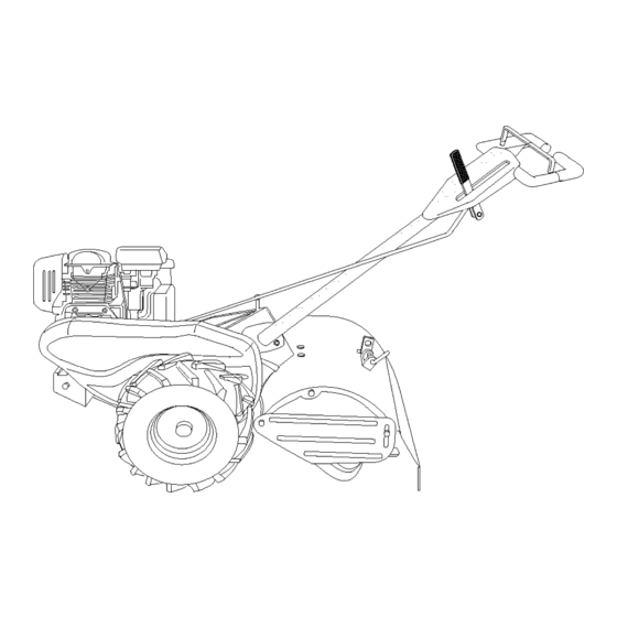
REAR TINE TILLER WITH
COUNTER ROTATING TINES
5.0 HP
17 Inch Tine Width
Model No.
917.294250
• Espahol, p. 21
This product has a low emission engine which operates
differently from previously
built engines. Before
start the
you
engine, read and understand
this Owner's Manual.
IMPORTANT:
Read and follow all Safety
Rules and Instructions
before
operating
this equipment.
Sears, Roebuck and Co., Hoffman Estates, IL 60179
U.S.A.
Visit our Craftsman website:www.sears.com/craftsman
Advertisement
Table of Contents
Troubleshooting

Related Manuals for Craftsman 917.294250


Summary of Contents for Craftsman 917.294250
- Page 1 Before start the engine, read and understand this Owner's Manual. IMPORTANT: Read and follow all Safety Rules and Instructions before operating this equipment. Sears, Roebuck and Co., Hoffman Estates, IL 60179 U.S.A. Visit our Craftsman website:www.sears.com/craftsman...
- Page 2 • If this Craftsman Tiller is used for commercial or rental purposes, this Warranty applies for only thirty (30) days from the date of purchase.
- Page 3 • Use extension cords and receptacles • Never operate the machine at high as specified by the manufacturer for all speeds on slippery surfaces. Look be- units with electric drive motors or elec- hind and use care when backing. tric starting motors. •...
- Page 4 In the state of California the above is PRODUCT SPECIFICATIONS required by law (Section 4442 of the Gasoline 2 Quarts California Public Resources Code). Other Capacity: Unleaded Regular states may have similar laws. Federal SAE 30 laws apply on federal lands. A spark ar- Oil (API-SF-SJ): rester for the muffler is available through (Capacity: 20 oz.)
- Page 5 These accessories were available when the tiller was produced. They are also available at most Sears retail outlets and service centers. Some of these accessories may not apply to your tiller. ENGINE SPARK PLUG MUFFLER AIR FILTER GAS CAN ENGINE OIL STABILIZER TILLER PERFORMANCE FUR_ENER...
- Page 6 Your new tiller has been assembled at the factory with the exception of those parts left unassembled for shipping purposes. To ensure safe and proper operation of your tiller all parts and hardware you assemble must be tightened securely. Use the correct tools as necessary to insure proper tightness.
- Page 7 Handle Column Tighten handle Cables _lock lever to hold Cable Clip Loosen Handle Lock handles14 Lever to Move CONNECT SHIFT Insert end of shift rod farthest from bend into hole of shift lever indicator. Insert hairpin clip through hole of shift 4.
- Page 8 These symbols may appearon yourTiller or in literaturesupplied with the product. Learn and understandtheir meaning. KNOW YOUR TILLER READ THIS OWNER'S MANUAL AND SAFETY RULES BEFORE OPERATING YOUR TILLER. Compare the illustrations with your tiller to familiarize yourself with the location various controls and adjustments.
- Page 9 The operation of any tiller can result in foreign objects thrown into the eyes, which can result in severe eye damage. Always wear safety glasses or eye shields before starting your tiller and while tilling. We recommend a wide vi- sion safety mask over spectacles or standard safety glasses.
- Page 10 CHECK ENGINE OIL LEVEL TURNING 1. Release the drive control bar. The engine in your unit has been shipped, 2. Move throttle control to "SLOW" posi- from the factory, already filled with SAE 30 tion. summer weight oil. 3. Place shift lever indicator in "F" (for- 1.
- Page 11 See "TO ADJUST CARBURETOR" in the CAUTION: Alcohol blended fuels (called gasohol or using ethanol or methanol) can Service and Adjustments section of this manual. attract moisture which leads to separa- tion and formation of acids during storage. NOTE: If engine does not start, see trou- Acidic gas can damage the fuel system bleshooting points.
- Page 12 ADJUST WHEELS CULTIVATING 1. Place blocks under right hand side of tiller and remove hairpin clip and clevis pin from right hand wheel. 2. Move wheel outward approximately inch until hole in inner wheel hub lines up with inner hole in axle. 3.
- Page 13 MAINTENANCE SCHEDULE FILL IN DATES AS YOU COMPLETE REGULAR SERVICE /_y_y SERVICE DATES Check Engine Oil Level Change Engine Oil 1_1,2 Oil Pivot Points Inspect Spark Arrester / Muffler Inspect Air Screen Clean or Replace Air Cleaner Cartridge Clean Engine Cylinder Fins Replace Spark Plug RH Gear Case Grease Fitting (loz,)
- Page 14 5. Refill engine with oil. See "CHECK _CAUTION: Disconnect spark plug ENGINE OIL LEVEl" in the Operation wire before performing any maintenance section of this manual. (except carburetor adjustment) to prevent accidental starting of engine. Prevent fires! Keep the engine free of grass, leaves, spilled oil, or fuel.
- Page 15 SPARK PLUG CLEANING Replace spark plugs at the beginning of Do not clean your tiller when the engine and transmission are hot. We do not rec- each tilling season or after every 50 hours of use, whichever comes first. Spark plug ommend using pressurized water (garden type and gap setting is shown in "PROD- hose, etc.) to clean your unit unless the...
- Page 16 TO REMOVE BELT GUARD 2. Remove old belt by slipping off engine pulley first then remove from trans- NOTE: For ease of removal, remove hair- mission pulley. pin clip and clevis pin from left wheel. Pull wheel out from tiller about 1 inch. 3.
- Page 17 • To maintain the superb tilling perfor- mance of this machine the tines should be checked for sharpness, wear, and bending, particularly the tines which are next to the transmission. If the gap between the tines exceeds 3-1/2 inches they should be replaced or straightened as necessary.
- Page 18 Immediately prepare your tiller for storage NOTE: Fuel stabilizer is an acceptable at the end of the season or if the unit will alternative in minimizing the formation of not be used for 30 days or more. fuel gum deposits during storage. _CAUTION: Never store the tiller with stabilizer to gasoline in fuel tank or stor-...
- Page 19 TROUBLESHOOTING CHART: See appropriate section in manual unless directed to Sears service center PROBLEM CAUSE CORRECTION Will not start 1. Out of fuel. 1. Fill fuel tank. 2. See "TO START ENGINE" in 2. Engine not "CHOKED" properly. the Operation section. 3.
- Page 20 TROUBLESHOOTING CHART: See appropriate section in manual unless directed to Sears service center PROBLEM CAUSE CORRECTION Engine 1. Low oil level/dirty oil. 1. Check oil level/change oil. overheats 2. Dirty engine air screen. 2. Clean engine air screen. 3. Dirty engine. 3.
- Page 21 Mantenimiento ..........GARANTIA LIMITADA DE DOS AI_IOS PARA LA CULTIVADORA CRAFTSMAN Por dos (2) ai_os, a partir de la fecha de compra, cuando esta Cultivadora Craftsman se mantenga, lubrique y afine segt]n las instrucciones para la operaci6n y et mantenimiento en el manual del dueEo, Sears repararA, gratis, todo defecto en el material y la mano de obra.
- Page 22 MANTENIMIENTO Y ALMACENAMIEN- • Despu_s de pegarle a un objeto extra5o, pare el motor, remueva el atambre de la bujfa, inspeccione la cultivadora cuidadosa- • Mantenga los accesorios y aditamentos de mente, para verificar si hay da_os, y repare la mAquina en buenas condiciones para el el da_o antes de volver a arrancar y operar funcionamiento.
- Page 23 REPARACION Capacidad de 2 Cuartos Congratulaciones por su buena compra. gasolina: Sin plomo, regular Su nuevo producto Craftsman® est#, diseSado Aceite(API-SF-SJ): SAE 30 (Sobre 40°F) y fabricado para funcionar de modo fiable por (Capacidad: 20 oz.) SAE 5w-30 SAE 10w-30 muchos aSos.
- Page 24 Estos accesorios estaban disponibles cuando se produjo la cultivadora. Tambi6n est#,n disponibles en la mayorfa de las tiendas de Sears y en los centros de servicio. Algunos de estos accesorios tal vez no se apliquen a su cultivadora. MOTOR BU3JA SILENCIADOR FILTRO DE AIRE LATA DE GASOMNA...
- Page 25 Su cultivadora nueva ha sido montada en la f&brica, con la excepci6n de aquellas partes que se dejaron sin montar per razones de envio. Para asegurarse que la cultivadora operar& en forma segura y adecuada, todas las partes y los arficulos de ferreteda que monte tienen que estar apre- tados en forma segura.
- Page 26 Conjunto del mango Columna del n "Arriba" Mango Apriete la palanca Cables de cierre del mango Abrazadera del Suelte la palanca de Cable moverla CONEXlON DE LA VARILLA DE CAMBIO Inserte el extremo de la varilla de cambio que est& m&s alejado de la dobladura, en el agujero del indicador de la palanca de cambio.
- Page 27 Estos s{mbolos pueden apareser sobre su cultivadora en la literature proporcionada con el pro- ducto, aprenda y comprenda sus significados. CONOZCA SU CULTIVADORA LEA ESTE MANUAL DEL DUEI_IO Y LAS REGLAS DE SEGURIDAD ANTES DE OPERAR SU CULTIVADORA Compare las ilustraciones con su cultivadora para familiarizarse con la ubicacibn de los diversos controles y ajustes.
- Page 28 La operaci6n de cualquier cultivadora puede hacer que salten objetos extraSos dentro de sus ojos, 1oque puede producir daSos graves en 6stos. Siempre use anteojos de seguridad o protecciones para los ojos antes de hacer arrancar su culti- vadora o mientras est6 labrando con 611a. Recomendamos el uso de la mascara de seguridad de visi6n amplia, para uso sobre los espejuelos o anteojos de seguridad estAnda£...
- Page 29 GIRO ANTES DE HACER ARRANCAR MOTOR Suelte la barra de control de la impulsi6n. Mueva el control de ta aceleraci6n a la IMPORTANTE: Tenga mucho cuidado de no posici6n de "LENTO" (SLOW). permitir que entre mugre al motor cuando Ponga el indicador de la patanca de cambio revise o aSada aceite o combustible.
- Page 30 IMPORTANTE: Cuando se opere en temper- AVISO: A mucha altura (sobre 3000 pies) o aturas por debajo de 32°F (0°C) use gasolina en climas fries (debajo de 40 ° F [4° C]) puede de invierno limpia y nueva para auedar a ase- que la mezcla del combustible det carburador gurar un buen arranque en clima fifo.
- Page 31 AJUSTE DE LAS RUEDAS PARA EL CULTIVO Ponga bloques debajo del lado derecho de la cultivadora y remueva la abrazadera de horquilla y la clavija de horquilla de la rueda del lade derecho. Mueva la rueda hacia afuera, aproximada- mente 1 pulgada, hasta que el agujero en el cubo de la rueda interior se alinee con el agujero interior en el eje.
- Page 32 PROGRAMA MANTENIMIENTO LLENE LAS FECHAS DE MEDIDA QUE COMPLETE FECHAS DE SERVICIO SERVICtO REGULAR o[ o7 Revisar el nivel del aceite del motor Cambiar el aceite del motor 1_,2 Aceitar los puntos de pivote lnspeccionar el supresor del silenciador lnspeccionar la rejilla de aire Limpiar/cambiar el cartucho...
- Page 33 Despu6s de que el aceite se haya drenado dHI, P RECAUClON: Desconecte el alambre de completamente, vuelva a colocar et tap6n la bujfa antes de dar mantenimiento (excepto del drenaje del aceite y apri6telo en forma por el ajuste del carburador) para evitar que el segura.
- Page 34 SlLENClADOR LIMPIEZA No opere la cultivadora sin el silenciador. No No limpie su cultivadora cuando el motor y la transmisi6n est6n calientes. No recomendamos manipulee el sistema de escape. Los silenciadores o los amortiguadores de chispas el uso de agua presurizada (manguera del daSados pueden crear un peligro de incendio.
- Page 35 PARA REMOVER LA PROTECCI()N DE LA Remueva la correa antigua desliz_ndola CORREA fuera de la polea del motor primero y rem- AVISO: Para facilitar la remoci6n, remueva la ueva la polea de la transmisi6n. Ponga la correa nueva en la ranura de abrazadera de horquilla y la clavija de horquilla la polea de ta transmisi6n y dentro de la de la rueda izquierda.
- Page 36 • Para que esta m&quina pueda mantener un rendimiento excelente en el labrado, se deben revisar los brazos para verificar si est#,n afilados, desgastados o doblados, especialmente los que se encuentran al lade de la transmisi6n. Si el espacio libre entre los brazos es mAs de 3-1/2 pulgadas, se tienen que cambiar o enderezar, segSn sea necesario.
- Page 37 AVISO: El estabilizador de combustible es una Inmediatamente prepare su cultivadora para el atmacenamiento al final de la temporada o si la altemativa aceptable para reducir a un minimo unidad no se va a usar per 30 dias o m&s. la formaci6n de dep6sitos de goma en et com- bustible durante el periodo de almacenamiento.
- Page 38 IDENTIFICACI(_N DE PROBLEMAS: Vea la seccidn apropiada en el manual a menos que estd dirigido a un centro de servicio Sears. CORRECCI()N PROBLEMA CAUSA No arranca Sin combustible. 1. Llene el estanque de combustible. Motor sin la "ESTRANGU- 2. Vea "PARA ARRANCAR MOTOR"...
- Page 39 IDENTIFICACION DE PROBLEMAS: Vea la seccibn apropiada en el manual a menos que estd dirigido a un centro de servicio Sears. CORRECCION PROBLEMA CAUSA Falta de fuerza 10.Rejilla de aire del motor sucia. 10. Limpie la rejilla de aire del motor. 11.Silenciador sucio/taponado.
- Page 40 TILLER - - MODEL NUMBER 917.294250 HANDLES 9_\\ & " Handle ass7 PART PART DESCRIPTION DESCRIPTION 141406 STD541437 Nut, Crownlock 3/8-16 Grip, Handle 110673X 19131611 Washer 13/32 x 1 x 11 Ga. Grommet, Handle 127254X 109228X Lever, Lock, Handle Bar, Drive Control Assembly 6712J 150628 Handle, Assemble...
- Page 41 TILLER - - MODEL NUMBER 917.294250 MAINFRAME, LEFT SIDE KEY PART PART NO. NO. DESCRIPTION DESCRIPTION 73510500 Nut, Keps 5/16-18 126875X Rivet, Drilled STD551137 Washer, Lock 3/8 4497H Retainer, Spring STD541037 Nut, He)( 3/8-16 165501X613 Guard, Belt 170127 Shield, Inner Belt Guard 132801 Belt, V 164329...
- Page 42 TILLER - - MODEL NUMBER 917.294250 MAINFRAME, RIGHT SIDE //" mainframe right 16 KEY PART PART NO. NO. DESCRIPTION DESCRIPTION 102190X Tire 73970500 Locknut, He)(, Flange 5/16-18 183122X624 102332X Bracket, Reinfomement 795R Tire Valve 102173X CounterWeight, R.H. STD551137 Washer, Lock 3/8 Engine, (See Breakdown) Honda Model No.
- Page 43 TILLER - - MODEL NUMBER 917.294250 TRANSMISSION transmission 19.5b PART PART DESCRIPTION DESCRIPTION 188554 Transmission Assembly (Includes 150737 Ground Shaft Assembly Key Nos. 2-52) 143008 Bearing, Shaft, Ground Drive R.H. 188482 Gearcase, LH. w/Bearing 106388X Spacer 0.70x 1.00x 1.150 (Includes Key No. 4) 102121X Sprocket and Gear Assembly 161963...
- Page 44 TILLER - - MODEL NUMBER 917.294250 TINE SHIELD fine shield PART PART DESCRIPTION DESCRIPTION 73900500 Nut, Lock Hex Fig 5/16-18 Uric 102701X Grip 161415X613 Shield, Side, Outer L H. STD541037 Nut, Hex 3/8-16 8393J Pin, Stake, Depth 102156X Stake, Depth 12000035 Ring, Klip 74930632...
- Page 45 TILLER - - MODEL NUMBER 917.294250 TINE ASSEMBLY tine ipb 1 KEY PART PART NO. NO. DESCRIPTION DESCRIPTION 74610616 Bolt, Hex 3/8-24 x 1 4459J Tine, Outer, LH. 132673 Pin, Shear 4460J Tine, Outer, R.H. 132728 Assembly, Hub and Plate, R.H. 6554J Tine, Inner, LH.
- Page 46 TILLER - - MODEL NUMBER 917.294250 DECALS PART DESCRIPTION 189358 Decal, Service CNTRL PNL 189334 Decal, Bit Guard 189335 Decal, Description 137538 Decal, Caution, Drive Control 120431X Decal, Hand Placement 102180X Decal, Shift Indicator 157984 Decal, Tine, Shield, Counter Rotating Tines 120075X Decal, Warning, Rotating Tines 163094...
- Page 47 TILLER - - MODEL NUMBER 917.294250 ENGINE, HONDA - - MODEL NUMBER GC160QHA2 CONTROL FAN COVER I CAMSHAFT RECOIL STARTER CARBURETOR I FLYWHEEL...
- Page 48 TILLER - - MODEL NUMBER 917.294250 ENGINE, HONDA - - MODEL NUMBER GC160QHA2 CONTROL RECOIL STARTER PART NO DESCRIPTION PART NO DESCRIPTION 5611074 Control assy. 6061204 Starter ass,/., Recoil *nhl * 5611132 Arm, governor 5611140 Rod, governor (black) 5611157 Spring, governor 5580634 Knob, recoil starter 5927033...
- Page 49 TILLER - - MODEL NUMBER 917.294250 ENGINE, HONDA - - MODEL NUMBER GC160QHA2 LABELS CYLINDER BARREL PISTON CRANKSHAFT ] •_i_i, ¸ MUFFLER L AIR CLEANER...
- Page 50 TILLER - - MODEL NUMBER 917.294250 ENGINE, HONDA - - MODEL NUMBER GC160QHA2 PISTON CYLINDER BARREL DESCRIPTION PART NO DESCRIPTION PART NO Ring set, piston (riken) 6842413 Cylinder assy. (010) 5655949 Ring set, piston (teikoku) 2399780 Clip, valve guide 6315717 Piston 6325211 Cover, head...
- Page 51 TILLER - - MODEL NUMBER 917.294250 ENGINE, HONDA - - MODEL NUMBER GC160QHA2 CRANKCASE COVER FUELTANK PART NO DESCRIPTION PART NO DESCRIPTION 7378482 6262422 Cover assy., Crankcase Pump assy., Fuel 3683646 4497947 Gasket, oil filler cap Rubber, supporter (107mm) 5611306 7310998 Gauge assy., Oil level Tube, diaphragm...
- Page 52 Your Home For repair - in your home - of all major brand appliances, lawn and garden equipment, or heating and cooling systems, no matter who made it, no matter who sold it! For the replacement parts, accessories owner's manuals that you need to do-it-yourself. For Sears professional installation of home appliances...