Advertisement
Quick Links
MAc.,. s )ff
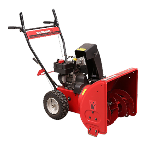
OPERATOR'S
MANUAL
SNOW
THROWER
Model 611
IMPORTANT:
READ SAFETY RULES AND INSTRUCTIONS
CAREFULLY
Warning:This
unit is equipped with an internal combustion engine and should not be used on or near any unimproved forest-
covered, brush-covered
or grass-covered land unless the engine's exhaust system is equipped with a spark arrester meeting
applicable local or state laws (if any). If a spark arrester is used, it should be maintained in effective working order by the operator.
In the State of California the above is required by law (Section 4442 of the California Public Resources Code). Other states may have
similar laws. Federal laws apply on federal lands. A spark arrester for the muffler is available through your nearest engine authorized
service dealer or contact the service department,
P.O. Box 368022 Cleveland, Ohio 44136-9722.
MTD PRODUCTS
INC. P.O. BOX 368022 CLEVELAND,
OHIO 44136-9722
PRINTED IN U.S.A.
FORM NO.770-10001A
6/99
Advertisement

Related Manuals for Yard Machines 247.88347


Summary of Contents for Yard Machines 247.88347
- Page 1 MAc.,. s )ff OPERATOR'S MANUAL SNOW THROWER Model 611 IMPORTANT: READ SAFETY RULES AND INSTRUCTIONS CAREFULLY Warning:This unit is equipped with an internal combustion engine and should not be used on or near any unimproved forest- covered, brush-covered or grass-covered land unless the engine's exhaust system is equipped with a spark arrester meeting applicable local or state laws (if any).
- Page 2 SECTION 1: FINDING YOUR MODEL NUMBER This Operators Manual is an important part of your new snow thrower. It will help you assemble, prepare and maintain your snow thrower. Please read and understand what it says. Before you start to prepare your snow thrower for its first use, please locate the model plate and copy the information from it in this Operators Manual.
- Page 3 SECTION 3: IMPORTANT SAFE OPERATION PRACTICES WARNING: THIS SYMBOL POINTS OUT IMPORTANT SAFETY INSTRUCTIONS WHICH, IF NOT FOLLOWED, COULD ENDANGER THE PERSONAL SAFETY AND/OR PROPERTY YOURSELF OTHERS. READ AND FOLLOW ALL INSTRUCTIONS IN THIS MANUAL BEFORE ATTEMPTING TO OPERATE YOUR SNOW THROWER. FAILURE TO COMPLY WITH THESE INSTRUCTIONS MAY RESULT IN PERSONAL INJURY.
- Page 4 • If the snow thrower should start to vibrate Never operate the machine at high transport abnormally,stop the engine and checkimmediately speeds on slipperysurfaces.Look behind and use for the cause. Vibration is generally a warning of care when backing. trouble. Never direct discharge...
- Page 5 SECTION 4- CONTENTS OF HARDWARE PACK Lay out the hardware according to the illustration for identification purposes. Part numbers are shown in parentheses. (Hardware pack may contain extra items which are not used on your unit.) (4)Lock Washers (C) ATTACHING THE CLUTCH GRIPS ATTACHING THE HANDLES...
- Page 6 SECTION 5" ASSEMBLY INSTRUCTIONS • Roll unit carton. Check carton IMPORTANT: After assembly, service engine thoroughly for loose parts before discarding. with gasoline, and check oil level as instructed in the separate engine manual packed with your unit. TOOLS REQUIRED FOR ASSEMBLY NOTE: References to right or left side of the snow •...
- Page 7 ATTACHING THE HANDLES (Hardware A) Lock Washer HexBolt Place right handle in position against the snow thrower so the flat side of the handle is against Saddle the frame. Secure bottom hole in handle to snow thrower using hex bolt (B) and lock washer (C). There are weld nuts welded to the inside of the frame for these bolts, See Figure 4.
- Page 8 ATTACHING THE HANDLE PANEL (Hardware C) Position the handle panel between handles. Insert carriage bolts (E) and secure with lock washers (C) and hex nuts (D). See Figure 8. ATTACHING SPEED SELECTOR PLATE AND SHIFT LEVER (Hardware D) Assemble speed selector plate to the outside of the handles as shown in Figure 9,...
- Page 9 ATTACHING THE CHUTE ASSEMBLY (Hardware F) Chute ..Assembly Place chute assembly over chute opening, with the opening in the chute assembly facing the front of the unit. Place chute flange keepers beneath lip of chute assembly, with the flat side of chute flange keeper facing downward.
- Page 10 FINAL ASSEMBLY AND ADJUSTMENTS Auger Control Cup _) Side Crown Side To check the adjustment of the auger control, push forward on the left hand clutch grip (depress the rubber bumper). There should be slack in the cable. Left Release clutch grip.
- Page 11 CHUTE DIRECTIONAL CONTROL TIRE PRESSURE (Pneumatic Tires) The chute directional control is located on left hand The tires are overinflated for shipping purposes. Check tire pressure and reduce to 15 to 20 psi. side of the snow thrower. See Figure 17. Refer tire sidewalls...
- Page 12 SECTION 7: OPERATION BEFORE STARTING Electric Starter: (If Equipped) WARNING: optional electric Labels on the snow thrower prior to starter is equipped with a three-wire WARNING: Observe Warning use. See Figure 2. power cord and plug, and is designed to operate volt household...
- Page 13 When engine starts, release starter button, and NOTE: Do not lose ignition key. Keep it in a safe move choke gradually to OFF. If engine falters, place. Engine will not start without the ignition key. move choke immediately to FULL and then Wipe all snow and moisture from the carburetor gradually to OFF.
- Page 14 SECTION 8: ADJUSTMENTS If adjustment is necessary, loosen the lock nut on the traction control cable and thread the chute or make any adjustments while WARNING: NEVER attempt to clean cable in or out as necessary. Tighten the lock engine is running. nut to secure the cable when correct adjustment is reached.
- Page 15 GEAR SHAFr SECTION 9: LUBRICATION Lubricate the gear shaft with a good al-weather multi-purpose light grease at least once a season or after every 25 hours of operation. WARNING: wire and ground Disconnect the spark plug against engine before performing repairs IMPORTANT: Keep all grease and oil off of the...
- Page 16 • To remove skid shoes, remove the four carriage bolts, cupped washers and hex nuts Drive which attach them to the snow thrower. Auger Belt Reassemble new skid shoes with the four Belt carriage bolts, cupped washers (cupped side Drive goes against skid shoes) and hex nuts.
- Page 17 DRIVE BELT Remove six self-tapping screws from the frame cover underneath the snow thrower. Follow steps through previous instructions. Remove the klick pins which secure the wheels, and remove the wheels from the axle. Pull idler pulley up, and lift belt off engine pulley Using a wrench to hold the shaft, loosen, but do and friction wheel disc.
- Page 18 SECTION 11" OFF-SEASON STORAGE NOTE: Fuel stabilizer is an acceptable alternative fuel tank indoors poorly in minimizing the formation of fuel gum deposits WARNING: Never store engine with ventilated areas, where fuel fumes may during storage. Add stabilizer to gasoline in fuel tank or storage container.
- Page 19 SECTION 12: Trouble Shooting Guide Trouble Possible Cause(s) Corrective Action Engine fails to start Fuel tank empty, or stale fuel. Fill tank with clean, fresh gasoline. Fuel will not last over thirty days unless a fuel stabilizer is used. Blocked fuel line. Clean fuel line.
- Page 20 Gear Assembly Model 611 • REF, PART REF. PART DESCRIPTION DESCRIPTION 618-0123 721-0325 Housing--R.H. Plug 618-0124 721-0327 Seal-Oil Housing_L.H. Hex Screw 1/4-20 x .75 Washer-Flat 710-0642 736-0351 Washer-Flat 711-1020 736-0369 Spiral Axle 22" 711-0908 736-0445 Washer-Flat Spiral Axle 24" 714_0161 737-0168 Grease 715-0143...
- Page 21 Engine and V-Belts Model 611 IMPORTANT: For a proper working machine, use Factory Approved Pads. V-BELTS are specially designed to engage and disengage safely. A substitute (non OEM) V-Belt can be dangerous by not disengaging completely. PART PART DESCRIPTION DESCRIPTION 710-1652 Hex Washer Screw 1/4-20 x.625 712-0181...
- Page 22 Blower Housing Model 611...
- Page 23 Blower Housing Model 611 REF. PART PART DESCRIPTION DESCRIPTION 712-0116 Lock Jam Nut 3/8-24 710-0703 Carriage Screw 1/4-20 x .75 756-0178 Flat Idler 710-0604 Hex Washer Screw 5/16-18 784-5632A Auger Idler Arm 736-0169 Lock Washer 3/8 710-0459A 712-0798 Hex Cap Screw 3/8-24 x 1.50 Hex Nut 3/8-16 738-0281 Shoulder Screw...
- Page 24 Handle Assembly Model 611...
- Page 25 Handle Assembly Model 611 PART PART DESCRIPTION DESCRIPTION 705-5234 Clutch Lever Assy - RH 736-0242 Bell Washer 720-0204 Grip 726-0100 Push Cap 731-1500 Pivot Rod Cover 720-0201A Chute Knob 747-0905 Pivot Rod 747-0697 Eyebolt 712-3010 Hex Nut 5/16-18 735-0234 Grommet only 736-0119 Lock Washer 5/16 705-5204A...
- Page 26 Frame Assembly Model 611 Drive Clutch Cable AugerClutch Cable 13" Wheels Auger Clutch Cable Blowe Housing...
- Page 27 Frame Assembly Model 611 PART PART DESCRIPTION DESCRIPTION 710-1652 Hex Screw 717-1445 Gear 784-5688 Drive Cable Guide Bracket 714-0126 784-5687A 717-1444 Auger Clutch Cable Bracket 7-Tooth Shaft 756-0625 Roller Cable 715-0249 Roll Pin 738-0924 Hex Screw 1/4-28 714-0143 Klik Pin 684-0030 684-0042B Frame Assembly...
- Page 28 MANUFACTURER'S LIMITED WARRANTY FOR: b. Routine maintenance items such as lubricants, filters, The limited warranty set forth below is given by MTD blade sharpening and tune-ups, or adjustments such PRODUCTS INC ("MTD") with respect to new merchan- as brake adjustments, clutch adjustments or deck dise purchased...