Table of Contents
Advertisement
Available languages
Available languages
Operator's
Manual
Snow Thrower
5.0 Horsepower
Electric Start
21-inch
Single Stage
Auger Propelled
Model 536.885213
CAUTION: Before using this product,
read this manual and follow all of its
Safety Rules and Operating Instructions.
CRRFTSMRN °
Manual del usario
Quitanieves
de 21 pulgadas
5.0 caballos
de fuerza
(hp)
Monoetapico
Arranque
el_ctrico
Propulsado
por barrena
Modelo 536.885213
PRECAUCION:
Antes de usar este producto,
lea este manual y siga todas las reglas de
seguridad e instrucciones de operaci6n.
/
Sears, Roebuck
and Co., Hoffman
Estates,
IL 60179 U.S.A.
F-011005M
www.sears.com/craftsman
Advertisement
Table of Contents

Related Manuals for Craftsman 536.885213


Summary of Contents for Craftsman 536.885213
- Page 1 (hp) Monoetapico Arranque el_ctrico Propulsado por barrena Modelo 536.885213 PRECAUCION: Antes de usar este producto, lea este manual y siga todas las reglas de seguridad e instrucciones de operaci6n. Sears, Roebuck and Co., Hoffman Estates, IL 60179 U.S.A. F-011005M www.sears.com/craftsman...
- Page 2 SERVICE AND ADJUSTMENT PARTS ORDERING/SERVICE LIMITED TWO-YEAR WARRANTY ON CRAFTSMAN SNOW THROWER For two years from the date of purchase, when this Craftsman Snow thrower is maintained, lubricated, and tuned up according to the operating and maintenance instructions in the owner's manual, Craftsman will repair, free of charge, any defect in material or workman- ship.
-
Page 3: Operation
TRAINING Always wear safety glasses or eye shields during operation or while performing an ad- Read the operating and service instruction justment or repair to protect eyes from manual carefully. Be thoroughly familiar foreign objects that may be thrown from the with the controls and the proper use of the snow thrower. -
Page 4: Maintenance
13. Never operate the snow t hrower near en- MAINTENANCE AND STORAGE closures, automobiles, window wells, Check shear bolts and other bolts at fre- drop-offs, and the like without proper ad- quent intervals for proper tightness to be justment of thesnow discharge angle. - Page 5 Drive Clutch Forward Reverse Auger Clutch Auger Collector Engage Push To Engage Fuel FueI OilMixture Electric Starter Discharge DOWN Discharge UP Discharge LEFT Discharge RIGHT Weight Transfer Weight Transfer Transmission Ignition Key Lift Handle To Depress Pedal Insert To Run, Engage To Disengage Pull Out To Stop.
-
Page 6: Tools Required
CARTON d_lb WARNING: Always wear while assembling snow 1. Locate and remove container of thrower. Craftsman 2-cycle oil. 2. Locate all parts packed separately TOOLS REQUIRED and remove from the carton. 1 - Knife to cut carton 3. Remove and discard the packing... -
Page 7: Product Specifications
_" CHECKLIST Before you operate your new snow thrower, to ensure that you receive the best performance and satisfaction from this quality product, please review the following checklist: _' All assembly instructions have been completed. _' The discharge chute rotates freely. No remaining loose parts in carton. -
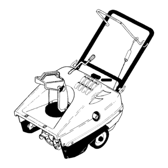
Page 8: Know Your Snow Thrower
KNOW YOUR SNOW THROWER READ THIS OWNER'S MANUAL AND SAFETY RULES BEFORE OPERATING YOUR SNOW THROWER. Compare the illustrations with your SNOW THROWER to familiarize yourself with the location of various controls and adjustments. Save this manual for future reference. Drive Lever Chute Deflector Ignition... -
Page 9: To Control Snow Discharge
HOW TO THROW SNOW The operation of any snow thrower can result in foreign objects being thrown 1. Engage the auger drive lever. into the eyes, which can result in se- 2. To stop throwing snow, release the vere eye damage. Always wear safety auger drive lever. -
Page 10: How To Mix The Fuel Mixture
FILL GAS: HOW TO MIX THE FUEL MIXTURE The two cycle engine, used on this NOTICE: ENGINES WHICH ARE CER- snow thrower, requires a mixture of TIFIED TO COMPLY WITH CALIFOR- gasoline and oil for lubrication of the NIA AND US EPA EMISSION bearings and other moving parts. -
Page 11: Before Starting The Engine
mable. Always use caution designed to operate on 120 ARNING: The starter is ARNING: Gasoline is flam- volt A.C. household current. when handling or storing gasoline. Carefully follow all instructions in Do not fill fuel tank while snow the "How To Start The Engine" sec- tion. -
Page 12: Warm Start
electric s tarter overheates, itwill a u- shutdown, leave choke at "OFF" and do tomatically stop and canonly bere- not push the primer button. If the en- started w hen ithascooled t oa safe gine fails to start, follow the Cold Start temperature. -
Page 13: Snow Throwing Tips
SNOW THROWING TIPS 10. After each snow throwing job, allow the engine to run for a few minutes. 1. When the handle is raised, the au- The snow and accumulated ice will ger blades will engage the ground melt off the engine. and the snow thrower will move for- 11. - Page 14 CUSTOMER RESPONSIBILITIES SERVICE R ECORDS Fillindatesasyou Before Every Every Every complete r egular Each Each Before SERVICE service. Often Hours Hours Hours Season Storage DATES Tighten Atl Screws and Nuts Check Spark Plug Lubricate Chute Control ..Flange Drain Fuel Check Fuel Check Auger Ddve _able Ad ustment...
-
Page 15: How To Remove The Top Cover
HOW TO REMOVE THE TOP COVER Top Cover 1. Remove the discharge chute. 2. Remove the fuel cap. 3. Remove the two bolts and nuts (A) from the front of the top cover. 4. Remove the two bolts (B) from the left and right side of the top cover. -
Page 16: How To Adjust The Chutecrank
the outer diameter of the worm tal starting when making any gear. ARNING: To prevent acciden- adjustments or repairs, always 4. Tighten the nuts. disconnect the spark plug wire and place it where it cannot make contact with the spark plug. HOW TO ADJUST THE CHUTECRANK Ifthe chute crank will not rotate fuIly to the... -
Page 17: How To Replace The Drive Belt
HOW TO REPLACE THE DRIVE BELT The drive belt is of special construction 7. Tip the auger enough to allow the auger to slide out of the auger and must be replaced with original fac- housing. tory replacement belt available from your nearest Sears authorized service 8. -
Page 18: How To Adjust The Brake Pad
HOW TO ADJUST THE BRAKE PAD The brake pad is adjusted at the factory 3. Tie the auger drive lever to the han- and a periodic adjustment is not neces- dle. This will engage the drive sys- tem. sary. IMPORTANT: An adjustment is only Loosen the screw and nut on the necessary if the brake pad has become brake pad arm (Figure 14). -
Page 19: To Adjust The Carburetor
TO ADJUST THE CARBURETOR The carburetor is not adjustable. En- proper engine speed. Over-speeding gine performance should not be af- the engine above the factory high fected at altitudes up to 7,000 feet. speed setting can be dangerous. If the operation at higher elevations, contact engine-governed high speed needs an... -
Page 20: Snow Thrower
If you do not remove the gasoline, tank, fumes may reach an open use fuel stabilizer supplied with unit flame, spark or pilot light from a fur- or purchase Craftsman Fuel Stabi- nace, water heater, clothes dryer, lizer No. 3550. Add fuel stabilizer to cigarette, etc. - Page 21 TROUBLE CAUSE CORRECTION Difficult starting Defective spark plug. Replace spark plug. Water or dirt in fuel system. Use carburetor bowl drain to flush and refill with fresh fuel mixture. Engine runs erratic Blocked fuel line, empty gas Clean fuel line; check fuel tank, or stale fuel mixture, supply;...
- Page 22 SEARS, ROEBUCK Federal and California Emission Control Systems Limited Warranty Small Off-Road Engines CALIFORNIA & US EPA EMISSION quired maintenance listed in your Owner's CONTROL WARRANTY STATEMENT Manual, but Sears, Roebuck and Co. will not deny warranty solely due to the lack of receipts The U.
- Page 23 ershall pay any charges formaking service Sears, Roebuck and Co. according to Subsec- calls and/or fortransporting theproducts tion 4 below. Any such part repaired or re- and from the place w here the inspection and/ placed under the ECS Warranty shall be orwarranty work i sperformed.
- Page 24 use shall not r educe Sears, Roebuck and Co. EMISSION-RELATED PARTS ECS Warranty obligations. INCLUDE THE FOLLOWING: 9.Unapproved add-on ormodified parts m ay 1. Carburetor Assembly and its Internal Com- not b eused t omodify orrepair aSears, Roe- ponents buck a nd C o. engine. Such u se voids this ECS a) Fuel filter Warranty and shall besufficient grounds for...
- Page 25 GARANTiA LIMITADA DE DOS A_IOS PARA EL QUITANIEVES CRAFTSMAN Durante dos argosa partir de la fecha de compra, siempre que a este quitanieves Craftsman se le de mantenJmJento,lubricaci6n y afinamiento de acuerdo con Ins instruccJones de operacidn y man- tenimiento presentadas en el manual de{ propietario, CRAFTSMAN reparar&, sin recargo a]guno, cua]quJer defecto en material y mano de obra.
- Page 26 CAPACITACION si6n con certificaci6n CSA/UL Use sola- mente tomacorrientes que hayan sido Lea con atenci6n las instrucciones en el instalados de acuerdo con los reglamen- manual de operaci6n y servicio. Familiari- tos de inspecci6n locales. cese completamente con los controles y Ajuste la altura del quitanieves para pasar el uso apropiado de la unidad.
- Page 27 alejado delabujia p ara e vitar unarranque 19. Nunca opere el quitanieves sin tener bue- accidental, na visibilidad o iluminaci6n. Asegt3rese 9. Tome todas lasprecauciones posibles al siempre que tiene buena estabilidad, y dejar elquitanieves desatendido. Desen- sujete con firmeza el mango de la unidad. ganche Iabarrena!propulsor, pare e lmo- Camine;...
- Page 28 B']]_I_t]Kt].'] IMPORTANTE: Muchos de estos simbolos estAn colocados en la unidad o est_n impresos en los manuales que vienen con el producto. Antes de operar Ia unidad aprenda y comprenda el objetivo de cada simbolo. Simbolos de control y operacion Despacio Rapido Arranque electrico...
- Page 29 Simbolos de control y operacion Mezcla de combustible Combustible Aceite y aceite Descarga hacia Descarga hacia Descarga hacia la Descarga hacia la ABAJO ARRIBA IZQUIERDA DERECHA i' o] Transferencia de peso Transterencia de peso Llave de encendido Levante el mango Presione el pedal Insertar para marcha, para enganchar,...
-
Page 30: Herramientas Necesarias
Contenido de la bolsa con las partes 1 - Manual del propietafio (no se muestra) 1 - Cable de arranque el_ctrico (no se 1- Botella de 3,2 onzas de muestra) aceite Craftsman de 2 tiem- C6MO SACAR EL QUlTANIEVES LA CAJA gafas protectoras o protectores... -
Page 31: Especificaciones
I ::1 _[,'..__,'q _vj I :] IV_,IJ_l _" LISTA DE REVISION Antes de operar su nuevo quitanieves, y pa- ra asegurar que obtenga el mejor rendimien- to y la mayor satisfacci6n de este producto de calidad, por favor haga un repaso de la siguiente lista de revisi6n: Se han completado todas las instruccio-... - Page 32 CONOZCA SU QUlTANIEVES LEA ESTE MANUAL DE INSTRUCCIONES Y LAS REGLAS DE SEGURIDAD TES DE OPERAR SU QUITANIEVES. Compare las ilustraciones con su QUITANIEVES para familiarizarse con la ubicaci6n de los diversos controles y ajustes. Guarde este manual para referencia futura. Palanca de propulsi6n Deflector del tubo de descarga...
- Page 33 La operaci6n decualquier quitanieves puede Para detener la descarga de nieve, suet- provocar que objetos extraSos seaR l anza- te la palanca de propulsion de la ba- dos con fuerza hacia s us ojos, Iocual podria rrena. resultar enlesiones graves. Use siempre gafas deseguridad oprotectores para l os...
- Page 34 C()MO PREPARAR LA MEZCLA TIPO DE COMBUSTIBLE DE COMBUSTIBLE AVISO: LOS MOTORES QUE EST_.N CER- El motor de dos tiempos de este quitanieves TIFICADOS PARA CUMPLIR CON LAS ES- requiere una mezcla de gasolina y aceite TIPULAClONES DE LAS NORMAS DE par8 lubricar los cojinetes y los demg=s com- EMISION EN EL ESTADO DE CALIFORNIA ponentes m6viles.
- Page 35 inflamable y debe tener mucho arranque esta diseSado para DVERTENCIA: El motor de ADVERTENCIA: La gasolina es funcionar con corriente domesti- cuidado al manipularla o alam* cenarla. ca de 120 voltios de CA. Siga cuidado- No Ilene el tanque de combustible mien- samente todas las instrucciones de la...
- Page 36 8. (Arranque electrico) Optima el boron very arrojar nieve en temperaturas inferiores de arranque el_ctrico hasta que el mo- a los 0°F(-18°C). tor arranque No optima el boron de arranque el_ctrico por mas de 10 se- ARRANQUEEN CALIENTE gundos cada vez. El arranque el_ctrico Siesta arrancando un motor caliente des-...
- Page 37 SUGERENCIAS PARA EL 10. Despu6s de cada trabajo deje que el LANZAMIENTO DE NIEVE motor funcione por unos minutos. se derretirA la nieve y el hielo acumula- Cuando se levanta el mango, las hojas dos en el motor. de caucho de la barrena entran en con- 11.
-
Page 38: Recomendaciones Generales
RESPONSABILIDADES DEL PROPIETARIO REGISTROSDE SERVICIO Antes Anote las fechas en Antes Cada Cada Cada Ceda FECHA quese hace de ca- A me- esta- gear- mantenimientoregular da uso nudo horas horas horas ei6n darlo SERVICIO Apretar todos _ostorni-' Ilos y tee cas Reviser la bujia Lo r,oa, o, r obor °... - Page 39 I_Vt !:I 1i i _111 I _NI_11 i lie1 C6MO QUITARLA CUBIERTA SUPERIOR Para montar la cubierta superior, reali- ce los pasos anteriores en order inver- Desmonte el tubo de desearga. Quite Ia tapa del tanque de combustible. Cubierta Superior Quite los dos pernos y tuercas (A) de la parle del frente de la cubierta super- ior.
- Page 40 de pulgada (3mm) entre Ia muesca del raborde y eI diametro exterior del torni- _hlL ADVERTENCIA: Para prevenir Iio ainfin. el arranque accidental del mo- tor, siempre desconecte el ca- Apriete Ias taercas. ble de la bujia y mantengalo alejado de esta, mientras realiza ajustes o repara- ciones a la unidad.
- Page 41 C(3MO REEMPLAZAR LA CORREA DE TRANSMISION La correa de transmisi6n esta construida es- Deslice la barrena fuera de la unidad de pecialmente para la unidad y debe ser reem- cojinetes en et lade derecho del quitanie- ves, plazada t3nicamente con una correa original de Ia fAbrica para su unidad, disponible en Incline la barrena suficiente para permi- su centro de servicio autorizado por Sears,...
- Page 42 COMO AJUSTAR LA ZAPATA DE FRENO La zapata de freno viene ajustada de fAbrica Esto mantendra enganchado el sistema de transmisi6n, y no es necesario el ajuste peri6dico. IMPORTANTE: El ajuste es necesario sola- Afloje el tornillo y la tuerca en el brazo mente si la zapata de freno se ha soltado o de la zapata de freno (Figura 14).
-
Page 43: Ajuste Del Carburador
AJUSTE DEL CARBURADOR el gobernador del motor, el cual fue configu- rado en la fAbrica para la velocidad apropia- El carburador no es ajustable. da del motor. Hacer que el motor exceda la El rendimiento de la unidad no debe verse velocidad del ajuste hecho en la fAbrica pue- de set muy peligroso. - Page 44 Craftsman No. 3550. ASada es- tabilizador de combustible a la cantidad NOTA: Para evitar dar_o al motor (si el quita- nieves no se usa por mAs 30 dias) siga los...
- Page 45 II f_,1 :] mL, II _] :11 m[o[o__,1 ml V L,_o,] [o] _h'dl :t :1 -.J_,1 :r±_ [o] _| _] _±\vj _ :t r±_ PROBLEMA CAUSA CORRECCION Dificultad para Buj_a defectuosa. Reemplace la bujia defectuosa. arrancar Agua o suciedad en et sistema Use el escurridor de la taza del de combustible, carburador para enjuagar;...
- Page 46 SEARS, ROEBUCK Garantia limitada de cumplimiento con el Sistema Federal de control de emisiones y con el sistema de control de emisiones del Estado de California Motores pequehos no aptos para carretera (off-road) CONTROL DE EMISIONES SISTEMA PARA EL CONTROL DE CALIFORNIA Y DE LA AGENCIA DE EMISIONES DEL FABRICANTE...
-
Page 47: Nota Importante
Sears, Roebuck and Co. o a Sears, Roebuck A. CAMPO DE APLICAOION: Esta garantia and Co. al 1-800-473-7247 (llamada gratuita de berA aplicarse a los motores peq ue5os para en E.U.A.). vehiculos off-road modelo 1995 y modelos de aSos posteriores en California (para otros es- NOTA IMPORTANTE tados, motores modelo 1997 y modelos de aSos posteriores). - Page 48 Garantia SCE d eberA garantizarse per elresto aprobada per S ears, Roebuck and Co. p ara del P eriodo delamisma. utilizarse eneldesempeflo decualquier man- tenimiento o cambio delaGarantia SCE, la 3.Cualquier parte g arantizada yreIacionada cual se proporcionarA sin cargo alguno para e l con emisiones que seespecifique para c am-...
- Page 49 For repair of major brand appliances in your own home.,. no matter who made it, no matter who sold it! iiiiiiiiiii 1-800-4-MY-HOME SM Any,_me day night (,-800469-4663! iiiiiiiiiii www.sears.com iiiiiiiiiii TO bring in products such as vacuums, lawn equipment and electronics for repair, call for the location of your nearest Sears Parts &...
- Page 50 CRAFTSMAN 21" 5HP SNOW THROWER 536.885213 ELECTRIC START ASSEMBLY 313974C Part No. Key No. Description 57569 RETAINER SCREW 311633 414106 WASHER, FLAT 271163 NUT, KEPS 56023 CORD, EXTENSION F-O11OO5M BOOK, INSTRUCTION F-011005M...
- Page 51 CRAFTSMAN 21" 5HP SNOW THROWER 536.885213 FRAME ASSEMBLY i102 333966 PART PART DESCRIPTION DESCRIPTION 333769-853 FRAME, RIGHT SIDE 73826 NUT, 1/4-20 333767 FRAME, LEFT SIDE 333739 TANK, FUEL 1.5QT 333987 CHANNEL, FRAME 762224 RING, FUEL TANK 180044 SCREW, 1/4-20X2.00 340300...
-
Page 52: Bearing & Plate
CRAFTSMAN 21" 5HP SNOW THROWER 536.885213 AUGER ASSEMBLY 511512 _8_482 520-2 520-8 333969 PART PART DESCRIPTION DESCRIPTION 340091 HOUS_NG_ AUGER 327072 AUGER, ASSY 302628 SCREW, 1/4-20X.75 520-2 302565 BLADE, AUGER RIVET 71067 WASHER, FLAT 520-6 49838 73826 NU_ 1/4-20 520-8... - Page 53 CRAFTSMAN 21" 5HP SNOW THROWER 536.885213 HANDLE ASSEMBLY 765_ 334312A Key No. Part No. Description 313449 CABLE, UPPER CONTROL 313441 LP BRKT, CABLE ADJ 313448 CABLE, LOWER CONTROL 308146 BOOT, CLUTCH SPRING 313471 SPRING, EXTENSION 333909-853 HANDLE, LOWER 313674 SCREW, 1/4-20X1.25 71067 WASHER, FLAT.
- Page 54 CRAFTSMAN 21" 5HP SNOW THROWER 536.885213 CHUTE ROD ASSEMBLY 334313 Key No. Part No. Description 337941 LF ROD, CHUTE 71072 WASHER, FLAT 71082 PIN, COTTER 313431 WASHER, CURVED SPRING 335264 SF ASSY, CHUTE CRANK BRKT 71072 WASHER, FLAT 57082 KNOB, SLEEVE...
- Page 55 CRAFTSMAN 21" 5HP SNOW THROWER 536.885213 DISCHARGE CHUTE ASSEMBLY 6°go _-. _'- v_,,_ 342233 Key No. Part No. Description 333859 RING, CHUTE 711752 SCREW 577021 GUIDE, CHUTE 762173 DONUT, FOAM 305862 CHUTE, LOWER 313686 SCREW, 1/4-20X 302635 NUT, CNTRLK 1/4-20...
- Page 56 CRAFTSMAN 21" 5HP SNOW THROWER 536.885213 TOP COVER ASSEMBLY 142143 173 _ 337370 181_ PART PART DESCRIPTION DESCRIPTION 340097 COVER, BOTTOM 335507 HOSE, PRIMER 313685 SCREW, 1/4-14X.75 271172 NUT, 1/4-20 761538 PANEL, ACCESS 340089 COVER, BELT 578109 NUT, 1/4-10 SPEED...
- Page 57 CRAFTSMAN 21" 5HP SNOW THROWER 536.885213 ENGINE DRIVE ASSEMBLY 7°7 "_._ \_ _ lh"d "_ L 31 SB300M PART PART DESCRIPTION DESCRIPTION ENGINE 48924 PULLEY, IDLER 180077 SCREW 302637 SCREW 18x16 WASHER 333970 LE PAD, BRAKE 301188 WASHER, FLAT 180077...
- Page 58 CRAFTSMAN 21" 5HP SNOW THROWER 536.885213 WHEEL ASSEMBLY 314097 Part No. Key No. Description 313678 AXLE 583409 WASHER, FLAT 760713 TIRE & RIM 583409 WASHER, FLAT 577598 RING, RETAINER F-O11005M...
- Page 59 CRAFTSMAN 21" 5HP SNOW THROWER 536.885213 DECALS NOTILLUSTRATED Part No. Description 340737 DECAL_ELECTRIC START 761568 DECAL, DASH 21"ES 761569 DECAL, SPARK PLUG ACCESS 48x378 DECAL, 5HP_I CRAFTSMAN 69880 DECAL, WARNING-HOT MUFFLER 318494 DECAL, CHOKE 70142 DECAL, DANGER CHUTE -HAND 70141...
- Page 60 CRAFTSMAN2-CYCLE ENGINEMODEL 143.025071 27 29 285 9 F-O11005M...
- Page 61 CRAFTSMAN2-CYCLE ENGINEMODEL 143.025071 PART PART DESCRIPTION DESCRIPTION RPM High 3700 to 4000 650891 Screw, 5/16-18 x 1-5/8" 250296A CylinderAss'y. 611049 Resistor Spark Plug (Incl. 75A, 105, 106, 138) (RCJ8Y) 490317 Governor Lever 570683 Port Cover 490304 Governor Lever 650959 Screw, 5/32 Allen 570721 Extension Spring 510326A...
- Page 62 CRAFTSMAN2-CYCLE ENGINEMODEL 143.025071 F-O11005M...
- Page 63 CRAFTSMAN2-CYCLE ENGINEMODEL 143.025071 PART DESCRIPTION 640088 Carburetor (Incl. 184 of Engine Parts List) 632538 Throttle Shaft & Lever Assembly 631621 Throttle Shutter 650506 Shutter Screw 632734 Choke Shaft & Lever Assembly 631815 Choke Shutter 630735 Choke Positioning Spring 632164 Fuel Fitting 631951 Float Bowl Assembly (Incl.
- Page 64 CRAFTSMAN2-CYCLE ENGINEMODEL 143.025071 PART PART DESCRIPTION DESCRIPTION 590670 Electric Starter (110 Volt) 590677 Thrust Spacer 34952 Retainer Ring 590659 Housing Ass'y. 590608 Dust Washer 590587 Brush & Spring Card 34953 Pinion Driver 590660 Commutator End Cap 590644 Anti-drift Spring 590661 Commutator End Bracket 34949A...
- Page 65 CRAFTSMAN2-CYCLE ENGINEMODEL 143.025071 _--14 m m-7 PART PART DESCRIPTION DESCRIPTION 590743 Rewind Starter 590643 Starter Housing Ass'y 590740 Retainer 590535 Starter Rope 590616 Starter Dog 590701 Starter Handle 590617 Dog Spring 590760 Spring Clip 590645A Pulley & Rewind Spring F-O11005M...