Enterasys RoamAbout RBT-4102 Installation Manual
Enterasys wireless access point installation guide
Hide thumbs
Also See for RoamAbout RBT-4102:
- Configuration manual (160 pages) ,
- Installation manual (72 pages) ,
- Installation manual (92 pages)

Related Manuals for Enterasys RoamAbout RBT-4102


Summary of Contents for Enterasys RoamAbout RBT-4102
- Page 1 Enterasys RoamAbout ® RBT-4102, RBT-4102-BG, RBT-4102C, RBT-4102C-EU, and RBT-4102-EU Wireless Access Point Installation Guide P/N 9034148-16...
- Page 3 ENTERASYS, ENTERASYS NETWORKS, ENTERASYS ROAMABOUT, LANVIEW, NETSIGHT, ROAMABOUT, WEBVIEW, and any logos associated therewith, are trademarks or registered trademarks of Enterasys Networks, Inc. in the United States and other countries. All other product names mentioned in this manual may be trademarks or registered trademarks of their respective companies.
- Page 4 RBT-4102, RBT-4102-BG, and RBT-4102-EU Federal Communication Commission Interference Statement This equipment has been tested and found to comply with the limits for a Class B digital device, pursuant to Part 15 of the FCC Rules. These limits are designed to provide reasonable protection against harmful interference in a residential installation.
- Page 5 EIRP is not more than required for successful communication. Because high power radars are allocated as primary users (meaning they have priority) in 5250-5350 MHz, these radars could cause interference and/or damage to license exempt LAN devices. RBT-4102-EU Australia/New Zealand AS/NZS 4771 N 826 Japan Telec Approval...
- Page 6 003NY05152 003GZ05053 003WY05076 003UX05009 EC Conformance Declaration Marking by the above symbol indicates compliance with the Essential Requirements of the R&TTE Directive of the European Union (1999/5/EC). This equipment meets the following conformance standards: • EN 60950 (IEC 60950) - Product Safety •...
- Page 7 Operation Using 5 GHz Channels in the European Community The user/installer must use the provided configuration utility to check the current channel of operation and make necessary configuration changes to ensure operation occurs in conformance with European National spectrum usage laws as described below and elsewhere in this document.
- Page 8 • The 5 GHz Turbo Mode feature is not allowed for operation in any of the countries. The current setting for this feature is found in the 5 GHz 802.11a Radio Settings Window as described in the user guide. • The 5 GHz radio's Auto Channel Select setting described in the user guide must always remain enabled to ensure that automatic 5 GHz channel selection complies with requirements.
- Page 9 RBT-4102C and RBT-4102C-EU Federal Communication Commission Interference Statement This equipment has been tested and found to comply with the limits for a Class B digital device, pursuant to Part 15 of the FCC Rules. These limits are designed to provide reasonable protection against harmful interference in a residential installation.
- Page 10 Cet appareil numérique respecte les limites de bruits radioélectriques applicables aux appareils numériques de Classe B prescrites dans la norme sur le matérial brouilleur: “Appareils Numériques,” NMB-003 édictée par l’Industrie. Industry Canada Statement Operation is subject to the following two conditions: 1) This device may not cause interference and 2) This device must accept any interference, including interference that may cause undesired operation of the device...
- Page 11 Countries of Operation & Conditions of Use in the European Community This device is intended to be operated in all countries of the European Community. Requirements for indoor vs. outdoor operation, license requirements and allowed channels of operation apply in some countries as described below: Note: The user must use the configuration utility provided with this product to ensure the channels of operation are in conformance with the spectrum usage rules for European Community countries as described below.
- Page 12 Operation Using 5 GHz Channels in the European Community The user/installer must use the provided configuration utility to check the current channel of operation and make necessary configuration changes to ensure operation occurs in conformance with European National spectrum usage laws as described below and elsewhere in this document.
- Page 13 remain enabled to ensure that automatic 5 GHz channel selection complies with requirements. The current setting for this feature is found in the 5 GHz 802.11a Radio Settings Window as described in the user guide. • This device is restricted to indoor use when operated using the 5.15 - 5.25 GHz band: Channels 36, 40, 44, 48.
-
Page 14: Declaration Of Conformity In Languages Of The European Community
German (DE) Hiermit erklärt Enterasys, dass sich dieser/diese/dieses Radio LAN device in Übereinstimmung mit den grundlegenden Anforderungen und den anderen rel- evanten Vorschriften der Richtlinie 1999/5/EG befindet". Eine Kopie der ursprünglichen Erklärung der Übereinstimmung kann von erh- alten werden Enterasys Networks, 50 Minuteman Road, Andover, Ma 01810, USA. - Page 15 προσ τισ ουσιωδεισ απαιτησεισ και τισ λοιπεσ σΧετικεσ διαταξεισ τησ οδηγιασ 1999/5/εκ. Ένα αντίγραφο της αρχικής ∆ιακήρυξης της συμμόρφωσης μπορεί να ληφθεί από Enterasys Networks, 50 Minuteman Road, Andover, Ma 01810, USA. Italian (IT) Con la presente Enterasys dichiara che questo Radio LAN device è conforme ai requisiti essenziali ed alle altre disposizioni pertinenti stabilite dalla direttiva 1999/5/CE.
- Page 16 SAFETY COMPLIANCE Power Cord Safety Please read the following safety information carefully before installing the access point: WARNING: Installation and removal of the unit must be carried out by qualified personnel only. • The unit must be connected to an earthed (grounded) outlet to comply with international safety standards.
- Page 17 Power Cord Set Europe The supply plug must comply with CEE7/7 (“SCHUKO”). The mains cord must be <HAR> or <BASEC> marked and be of type HO3VVF3GO.75 (minimum). IEC-320 receptacle.
- Page 18 This product complies with the requirements of European Directive, 2002/95/EC, Restriction of Hazardous Substances (RoHS) in Electrical and Electronic Equipment EUROPEAN WASTE ELECTRICAL AND ELECTRONIC EQUIPMENT In accordance with Directive 2002/96/EC of the European Parliament on waste electrical and electronic equipment (WEEE): The symbol above indicates that separate collection of electrical and electronic equipment is required and that this product was placed on the European market after August 13, 2005, the date of enforcement for Directive 2002/96/EC.
- Page 19 CAREFULLY READ THIS LICENSE AGREEMENT. This document is an agreement (“Agreement”) between the end user (“You”) and Enterasys Networks, Inc. on behalf of itself and its Affiliates (as hereinafter defined) (“Enterasys”) that sets forth Your rights and obligations with respect to the Enterasys software program/firmware installed on the Enterasys product (including any accompanying documentation, hardware or media) (“Program”) in the package and...
- Page 20 derivative works based on the Program, in whole or in part. (iii) Publish, disclose, copy, reproduce or transmit the Program, in whole or in part. (iv) Assign, sell, license, sublicense, rent, lease, encumber by way of security interest, pledge or otherwise transfer the Program, in whole or in part. (v) Remove any copyright, trademark, proprietary rights, disclaimer or warning notice included on or embedded in any part of the Program.
- Page 21 UNITED STATES GOVERNMENT RESTRICTED RIGHTS. The enclosed Program (i) was developed solely at private expense; (ii) contains “restricted computer software” submitted with restricted rights in accordance with section 52.227-19 (a) through (d) of the Commercial Computer Software-Restricted Rights Clause and its successors, and (iii) in all respects is proprietary data belonging to Enterasys and/or its suppliers.
- Page 22 AUDIT RIGHTS. You hereby acknowledge that the intellectual property rights associated with the Program are of critical value to Enterasys and, accordingly, You hereby agree to maintain complete books, records and accounts showing (i) license fees due and paid, and (ii) the use, copying and deployment of the Program. You also grant to Enterasys and its authorized representatives, upon reasonable notice, the right to audit and examine during Your normal business hours, Your books, records, accounts and hardware devices upon which the Program may be deployed to verify compliance with this Agreement,...
- Page 23 13. SEVERABILITY. In the event any provision of this Agreement is found to be invalid, illegal or unenforceable, the validity, legality and enforceability of any of the remaining provisions shall not in any way be affected or impaired thereby, and that provision shall be reformed, construed and enforced to the maximum extent permissible.
- Page 24 Compliances xxii...
-
Page 25: Table Of Contents
Table of Contents Preface Purpose...xxv Intended Audience ...xxv Associated Documents ...xxv Getting Help ... xxvi Chapter 1: Introduction Package Checklist ...1-2 Hardware Description ...1-2 Component Description ...1-4 Chapter 2: Hardware Installation Chapter 3: Access Point Configuration Using the CLI ...3-1 Required Connections ...3-1 Logging In ...3-2 Using Web Management ...3-6... - Page 26 Contents Wiring Map for Serial Cable ...B-4 Appendix C: Specifications General Specifications ... C-1 Maximum Channels ... C-1 Data Rate ... C-1 Modulation Type ... C-2 Network Configuration ... C-2 Operating Frequency ... C-2 AC Power Adapter ... C-2 Unit Power Supply ... C-2 PoE (DC) ...
-
Page 27: Preface
You can download the documentation from the Enterasys Networks web site, http://www.enterasys.com/products/wireless: • RoamAbout RBT-4102 Wireless Access Point Configuration Guide This document provides the information to configure and manage the RBT-4102 Wireless Access Point. • RoamAbout RBT-4102 / RBT-1602 Wireless Access Point Antenna Site... -
Page 28: Getting Help
• A description of the failure • A description of any action(s) already taken to resolve the problem • The serial and revision numbers of all involved Enterasys Networks products in the network • A description of your network environment (for example, layout, and cable type) •... -
Page 29: Chapter 1: Introduction
10/100 Mbps Ethernet LAN. The RBT-4102 supports up to eight Virtual Access Points per physical radio interface, that is eight on the 802.11a radio and eight on the 802.11g radio. This allows traffic to be separated for different user groups using an access point that services one area. -
Page 30: Package Checklist
Package Checklist The RoamAbout package includes: • One RoamAbout access point • One RS-232 console cable • One AC power adapter and power cord • Four rubber feet • Three wall-mounting screws • Bezel • Mounting bracket • Documentation CD (includes this document). Please go to http://www.enterasys.com Inform your dealer if there are any incorrect, missing or damaged parts. -
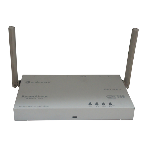
Page 31: Rear Panel
Hardware Description Rear Panel External Antenna DC Power Reset Security External Antenna RJ-45 Port, Console Connector Supply Button Slot Connector Port (802.11a) Radio Connector (802.11b/g Radio) -
Page 32: Component Description
For a list of external antennas, their model type and gain refer to “External Antennas” on page C-8. For information on the external antennas available, refer to the RoamAbout RBT-4102 / RBT-1602 Wireless Access Point Antenna Site Preparation and Installation Guide. This document is available for download from http://www.enterasys.com/products/wireless. -
Page 33: Security Slot
Status Power On Green Flashing Green On Amber Flashing Amber (Prolonged) Ethernet Link On Green Flashing Green Wireless Link On Green Flashing Green Wireless Link On Green Flashing Green Security Slot The access point includes a Kensington security slot on the rear panel. You can prevent unauthorized removal of the access point by wrapping the Kensington security cable (not provided) around an unmovable object, inserting the lock into the slot, and turning the key. -
Page 34: Ethernet Port
Ethernet Port The access point has one 10BASE-T/100BASE-TX RJ-45 port that can be attached directly to 10BASE-T/100BASE-TX LAN segments. These segments must conform to the IEEE 802.3 or 802.3u specifications. This port supports automatic MDI/MDI-X operation, so you can use straight-through cables for all network connections to PCs, switches, or hubs. -
Page 35: Reset Button
Reset Button This button is used to reset the access point or restore the factory default configuration. If you hold down the button for less than 5 seconds, the access point will perform a hardware reset. If you hold down the button for 5 seconds or more, any configuration changes you may have made are removed, and the factory default configuration is restored to the access point. - Page 36 Introduction...
-
Page 37: Chapter 2: Hardware Installation
Chapter 2: Hardware Installation To install the access point, follow the steps outlined below: Select a Site – Choose a proper place for the access point. In general, the best location is at the center of your wireless coverage area, within line of sight of all wireless devices. - Page 38 • Using the mounting bracket, mark the position of the four screw holes on the wall or ceiling. For concrete or brick walls, you will need to drill holes and insert wall plugs for the screws. • Position the mounting bracket over the wall or ceiling screw holes, then insert the included screws and tighten them down to secure the bracket firmly to the wall or ceiling.
- Page 39 For example, if the access point is mounted on a horizontal surface, both antennas should be positioned pointing vertically up to provide optimum coverage. Connect the Console Port – Connect the console cable (included with RBT-4102) to the RS-232 console port for accessing the command-line interface. You can manage the access point using the console port, the web interface, or SNMP management software such as Enterasys NetSight, or HP’s OpenView.
- Page 40 Hardware Installation...
-
Page 41: Chapter 3: Access Point Configuration
You can manage the RoamAbout Access Point 4102 with: • The Command Line Interface (CLI) accessed through a direct connection to the console port. Refer to the RoamAbout RBT-4102 Wireless Access Point Configuration Guide to view a complete list of all of the CLI commands, and how to use them. -
Page 42: Logging In
• Set the emulation mode to VT100. • When using HyperTerminal, select Terminal keys, not Windows keys. Note: When using HyperTerminal with Microsoft® Windows® 2000, make sure that you have Windows 2000 Service Pack 2 or later installed. Windows 2000 Service Pack 2 fixes the problem of arrow keys not functioning in HyperTerminal’s VT100 emulation. - Page 43 Enter country ? to display the list of countries. RoamAbout 4102#country ? WORD Country code: AL-ALBANIA, DZ-ALGERIA, AR-ARGENTINA, AM-ARMENIA, AU-AUSTRALIA, AT-AUSTRIA, AZ-AZERBAIJAN, BH-BAHRAIN, BY-BELARUS, BE-BELGIUM, BZ-BELIZE, BO-BOLVIA, BR-BRAZIL, BN-BRUNEI DARUSSALAM, BG-BULGARIA, CL-CHILE, CN-CHINA, CO-COLOMBIA, CR-COSTA RICA, HR-CROATIA, CY-CYPRUS, CZ-CZECH REPUBLIC, DK-DENMARK, DO-DOMINICAN REPUBLIC, EC-ECUADOR, EG-EGYPT, SV-EL SALVADOR, EE-ESTONIA, FI-FINLAND, FR-FRANCE, GE-GEORGIA, DE-GERMANY, GR-GREECE, GT-GUATEMALA, HN-HONDURAS, HK-HONG KONG, HU-HUNGARY,...
- Page 44 Enter no ip dhcp to disable DHCP. RoamAbout 4102(if-ethernet)#no ip dhcp DHCP client state has changed. Please reset AP for change to take effect. RoamAbout 4102(if-ethernet)#exit RoamAbout 4102#reset board Reboot system now? <y/n>: y Username: admin Password:******** RoamAbout 4102#configure Enter configuration commands, one per line. End with CTRL/Z RoamAbout 4102(config)#interface ethernet Enter Ethernet configuration commands, one per line.
- Page 45 The switch port must also be configured to accept the access point’s management VLAN ID and native VLAN IDs. RoamAbout 4102(config)#management-vlanid 10 Reboot system now? <y/n>:y Username: admin Password:******** Refer to the RoamAbout RBT-4102 Wireless Access Point Configuration Guide for advanced configuration.
-
Page 46: Using Web Management
Using Web Management Notes: • The default username is admin, and the default password is password. • To get help, click on Help, located at the bottom of the screen. • You must click on the Apply button, located at the bottom of the each Web interface page for the configuration to take effect. - Page 47 Enter the default username admin and the default password password, and click LOGIN. • If applicable, the Country Code page appears, go to step 3. • If the Country Code page does not appear, go to step 4. If applicable, set the Country Code: Click the arrow in the Country pull-down menu to select the appropriate country, then click Apply at the bottom of the page.
- Page 48 Click the Reset button next to Reset Access Point, located at the bottom of the page. The access point prompts you to confirm that you want to reboot the system. Click OK. The access point reboots, and the Login window appears. Enter the username admin and the password password, and click LOGIN.
- Page 49 Go to step 4. Enter the following information, and click Apply. • System Name is an alias used for the access point, enabling the device to be uniquely identified on the network. Default: RoamAbout AP. Length: 1 to 22 characters •...
- Page 50 Enter the IP Address, Subnet Mask, Default Gateway, and Primary and Secondary DNS. Note: Enterasys Networks recommends that you reset the access point after changing the DHCP client status. • IP Address is the IP address of the access point. Valid IP addresses consist of four decimal numbers, 0 to 255, separated by periods.
- Page 51 • Default Gateway is the IP address of the router for the access point, which is used if the requested destination address is not on the local subnet. If you have management stations, DNS, RADIUS, or other network servers located on another subnet, type the IP address of the default gateway router in the text field provided.
- Page 52 To change the username and password. Click Administration from the menu on the left hand side of the page. The Administration page appears. Specify a new username in the Username field. Specify a new password in the Password field. Specify the new password again in the Confirm Password field. Click Apply at the bottom of the page.
- Page 53 The access point displays a Settings Saved message. Click OK. To specify the management VLAN ID: Click Filter Control from the menu. The Filter Control page appears. 3-13...
- Page 54 The switch port must also be configured to accept the access point’s management VLAN ID and native VLAN IDs. Click Apply at the bottom of the page. Refer to the RoamAbout RBT-4102 Wireless Access Point Configuration Guide for more information about advanced configuration. 3-14...
-
Page 55: Chapter 4: Network Configuration
Chapter 4: Network Configuration Wireless networks support a standalone configuration as well as an integrated configuration with 10/100 Mbps Ethernet LANs. The RoamAbout RBT-4102 also provides bridging services that can be configured independently on either the 5 GHz or 2.4 GHz radio interfaces. -
Page 56: Network Topologies
Network Topologies Ad Hoc Wireless LAN (no Access Point) An ad hoc wireless LAN consists of a group of computers, each equipped with a wireless adapter, connected via radio signals as an independent wireless LAN. Computers in a specific ad hoc wireless LAN must therefore be configured to the same radio channel. An ad hoc wireless LAN can be used for a branch office or SOHO operation. -
Page 57: Infrastructure Wireless Lan
Infrastructure Wireless LAN The access point also provides access to a wired LAN for wireless workstations. An integrated wired/wireless LAN is called an Infrastructure configuration. A Basic Service Set (BSS) consists of a group of wireless PC users, and an access point that is directly connected to the wired LAN. -
Page 58: Infrastructure Wireless Lan For Roaming Wireless Pcs
Network Configuration Infrastructure Wireless LAN for Roaming Wireless PCs The Basic Service Set (BSS) defines the communications domain for each access point and its associated wireless clients. The BSS ID is a 48-bit binary number based on the access point’s wireless MAC address, and is set automatically and transparently as clients associate with the access point. -
Page 59: Infrastructure Wireless Bridge
The access point supports WDS bridge links on either the 5 GHz (802.11a) or 2.4 GHz (802.11b/g) bands, and can be used with various external antennas to offer flexible deployment options. For external antenna information, refer to the RoamAbout RBT-4102 / RBT-1602 Wireless Access Point Antenna Site Preparation and Installation Guide. - Page 60 Network Configuration...
-
Page 61: Appendix A: Troubleshooting
Symptom Power LED is Off Power LED is Amber Ethernet/Link LED is Off Note: For troubleshooting wireless connectivity problems, refer to the RoamAbout RBT-4102 Wireless Access Point Configuration Guide. Troubleshooting Chart Action • AC power adapter may be disconnected. Check connections between the access point, the power adapter, and the wall outlet. - Page 62 Troubleshooting...
-
Page 63: Appendix B: Cables And Pinouts
Appendix B: Cables and Pinouts Twisted-Pair Cable Assignments For 10/100BASE-TX connections, a twisted-pair cable must have two pairs of wires. Each wire pair is identified by two different colors. For example, one wire might be green and the other, green with white stripes. Also, an RJ-45 connector must be attached to both ends of the cable. -
Page 64: 10/100Base-Tx Pin Assignments
10/100BASE-TX Pin Assignments Use unshielded twisted-pair (UTP) or shielded twisted-pair (STP) cable for RJ-45 connections: 100-ohm Category 3 or better cable for 10 Mbps connections. Also be sure that the length of any twisted-pair connection does not exceed 100 meters (328 feet). The RJ-45 port on the access point supports automatic MDI/MDI-X operation, so you can use straight-through or crossover cables for all network connections to PCs, switches, or hubs. -
Page 65: Straight-Through Wiring
Straight-Through Wiring If the twisted-pair cable is to join two ports and only one of the ports has an internal crossover (MDI-X), the two pairs of wires must be straight-through. End A Crossover Wiring If the twisted-pair cable is to join two ports and either both ports are labeled with an “X” (MDI-X) or neither port is labeled with an “X”... -
Page 66: Console Port Pin Assignments
Console Port Pin Assignments The DB-9 console port on the front panel of the access point is used to connect to the access point for out-of-band console configuration. The command-line configuration program can be accessed from a terminal, or a PC running a terminal emulation program. -
Page 67: Appendix C: Specifications
RBT-4102C-EU ETSI: 4 channels (normal mode) Japan: 8 channels (normal mode) RBT-4102-EU ETSI: 19 channels (normal mode) Japan: 15 channels (normal mode) 802.11b/g RBT-4102, RBT-4102C FCC/IC: 1-11 RBT-4102C-EU, RBT-4102-EU ETSI: 1-13 France: 10-13 Japan: 1-13 b/g Japan: 1-14 b only Data Rate 802.11a... -
Page 68: Modulation Type
802.11b: CCK, BPSK, QPSK Network Configuration Infrastructure Operating Frequency 802.11a: RBT-4102, RBT-4102-BG, RBT-4102-EU: 5.15 ~ 5.35 GHz US/Canada, Europe, Japan 5.470 ~ 5.725 GHz (Europe) 5.725 ~ 5.825 GHz US/Canada 4.92 ~ 4.98 GHz Japan 5.04 ~ 5.08 GHz Japan RBT-4102C, RBT-4102C-EU: 5.15 ~ 5.25 GHz US/Canada, Europe, Japan... -
Page 69: Physical Size
General Specifications Physical Size 21.83 x 13.73 x 3.27 cm (8.60 x 5.40 x 1.29 in) Weight 0.687 kg (1.514 lbs) LED Indicators Power, Ethernet Link/Activity, 11a and 11g Wireless Link/Activity Network Management Web-browser, RS232 console, Telnet, SSH, SNMP Temperature °... -
Page 70: Compliances
EN 301.893, EN 300.328, EN 301.489-1, EN 301.489-17 ARB STD-T70, ARB STD-66, RCR STD-33, ARB STD-T71 (Japan) Safety UL/CUL (CSA 22.2 No. 60950-1 & UL60950-1) EN60950-1 (T V/GS), EN60601, IEC60950-1 (CB) Ü EN60601 (RBT-4102-EU PoE only) Standards IEEE 802.3 10BASE-T, IEEE 802.3u 100BASE-TX, IEEE 802.11a, b, g... -
Page 71: Sensitivity
Sensitivity IEEE 802.11a Sensitivity (GHz - dBm) Modulation/Rates 5.15-5.250 BPSK (6 Mbps) BPSK (9 Mbps) QPSK (12 Mbps) QPSK (18 Mbps) 16 QAM (24 Mbps) 16 QAM (36 Mbps) 64 QAM (48 Mbps) 64 QAM(54 Mbps) IEEE 802.11g Data Rate 6 Mbps 9 Mbps 12 Mbps... -
Page 72: Transmit Power
Transmit Power IEEE 802.11a Maximum Output Power (GHz - dBm) Data Rate 5.15-5.250 6 Mbps 9 Mbps 12 Mbps 18 Mbps 24 Mbps 36 Mbps 48 Mbps 54 Mbps IEEE 802.11g Maximum Output Power (GHz - dBm) Data Rate 2.412 6 Mbps 9 Mbps 12 Mbps... -
Page 73: Operating Range
Operating Range The operating range distances listed in the following tables are for typical Note: environments only. Operating ranges can vary considerably depending on factors such as local interference and barrier composition. It is recommended to do a site survey to determine the maximum ranges for specific access point locations in your environment. -
Page 74: External Antennas
External Antennas The RBT-4102, RBT-4102-BG, and the RBT-4102C are certified by the FCC, for use in the United States, to operate with these antennas: High gain point to point antenna, model RBTES-AH-P23M (Gain 23 dBi), is certified Note: under specific point to point condition and the use of point to multipoint systems, omnidirectional applications, and multiple co-related intentional radiators transmitting the same information is prohibited. - Page 75 2.4-2.5 GHz Directional Panel, outdoor For information on the external antennas supported by the access point, refer to the RoamAbout RBT-4102 / RBT-1602 Wireless Access Point Antenna Site Preparation and Installation Guide available from the Enterasys Networks web site: http://www.enterasys.com/support...
- Page 76 Specifications C-10...
-
Page 77: Index
Index antennas, positioning Basic Service Set See BSS cable assignments change username and password channels, maximum change username and password country code configuring default username and password disable DHCP Gateway address IP address configuring logging in VLAN management console port connecting pin assignments country codes... - Page 78 power connection Power over Ethernet See PoE power supply, specifications reset button set username and password web management 3-12 specifications subnet mask 3-10 system location length system name length troubleshooting using the CLI VLAN management web management 3-13 web management country code logging in set static address...