Table of Contents
Advertisement
OPERATOR'S
MANUAL
II:RRFTSMRN I
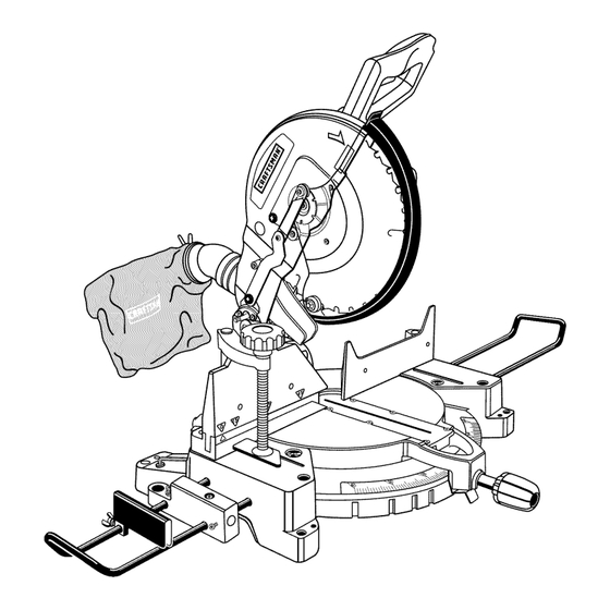
12 in. COMPOUND
MITER SAW
DOUBLE INSULATED
Model No.
315.212050
_
WARNING:
To reduce the risk of injury,
the user must read and understand the
operator's manual before using this product.
Customer
Help Line: t-800-932-3188
Sears, Roebuck
and Co., 3333 Beverly Rd., Hoffman
Estates, IL 60179 USA
Visit the Craftsman web page: www.sears.com/craftsman
983000-549
6-04
Save this manual for future reference
Advertisement
Table of Contents

Related Manuals for Craftsman 315.212050


Summary of Contents for Craftsman 315.212050
- Page 1 Customer Help Line: t-800-932-3188 Sears, Roebuck and Co., 3333 Beverly Rd., Hoffman Estates, IL 60179 USA Visit the Craftsman web page: www.sears.com/craftsman Save this manual for future reference 983000-549 6-04...
-
Page 2: One Year Full Warranty
ONE YEAR FULL WARRANTY ON CRAFTSMAN TOOL If this Craftsman tool fails due to a defect in material or workmanship within one year from the date of purchase, CONTACT THE NEAREST SEARS PARTS & REPAIR CENTER at 1-800-4-MY-HOME ® and Sears will repair it, free of charge. - Page 3 • SECURE WORK. Use clamps or a vise to hold work _IL WARNING: Read and understand all instruc- tions. Failure to follow all instructions listed below, when practical. It's safer than using your hand and may result in electric shock, fire and/or serious frees both hands to operate tool.
- Page 4 • INSPECT TOOL CORDS PERIODICALLY. If damaged, • DO NOT USE TOOL IF SWITCH DOES NOT TURN IT haverepaired bya qualified service technician at ON AND OFF. Have defective switches replaced by an anauthorized s ervice facility. T heconductor w ith authorized service center.
- Page 5 • NEVER reach to pickupa workpiece, a pieceof scrap, • MAKE SURE THE WORK AREA HAS AMPLE LIGHT- or anything elsethatis inor nearthe cuttingpathofthe ING to see the work and that no obstructions will inter- blade. fere with safe operation BEFORE performing any work •...
-
Page 6: Symbols
Someofthefollowing symbols maybeusedonthistool.Please studythemandlearn theirmeaning. Proper interpretation ofthesesymbols willallowyouto operate thetoolbetterandsafer. SYM BOL NAM E DESIG NATION/EXPLANATION Volts Voltage Amperes Current Hertz Frequency ( cycles persecond) Watt Power Minutes Time "%, Alternating Current Type of current Direct Current Type or a characteristic of current No Load Speed Rotational speed, at no load... - Page 7 Thefollowing signal w ordsandmeanings a reintended to explain the levels ofriskassociated withthis product. SYMBOL SIGNAL MEANING Indicates an imminently hazardous situation, which, if not avoided, will DANGER: result in death or serious injury. Indicates a potentially hazardous situation, which, if not avoided, could WARNING: result in death or serious injury.
-
Page 8: Double Insulation
DOUBLE INSULATION EXTENSION CORDS Double insulation is a concept in safety in electric power When using a power tool at a considerable distance from tools, which eliminates the need for the usual three-wire a power source, be sure to use an extension cord that has grounded power cord. - Page 9 Anti-Kickback Pawls (radial arm and table saws) Non-Through Cuts A devise which, when properly installed and maintained, Any cutting operation where the blade does not extend is designed to stop the workpiece from being kicked back completely through the thickness of the workpiece. toward the front of the saw during a ripping operation.
- Page 10 PRODUCT SPECIFICATIONS Cutting Capacity with Miter at 0°/Bevel 0°: Maximum nominal ]umber sizes: ....2 x 8, 4 x 4 Blade Diameter ....12 in. (305 mm) Cutting Capacity with Miter at 45°/Bevel 0°: Blade Arbor ....... 5/8 in. Maximum nominal lumber sizes: ......2 x 6 No Load Speed ......
-
Page 11: Features
KNOW YOUR COMPOUND MITER SAW SPINDLE LOCK BUTTON See Figure 1. See Figure 3. Before attempting to use this product, familiarize yourself A spindle lock button has been provided for locking the with all operating features and safety rules. spindle which keeps the blade in your saw from rotating. Depress and hold the lock button while installing, chang- 15 AMP MOTOR ing, or removing blade. - Page 12 ROTATING BEVEL LOCK KNOB HANDLE The bevel lock knob securely locks your compound miter saw at desired bevel angles. A positive stop adjustment screw has been provided on each side of the saw arm. These adjustment screws are for making fine adjustments HANDLE at 0 and 45 °.
- Page 13 Thefollowing tools(notincluded) areneeded forchecking adjustments o fyoursaworforinstalling theblade: PHILLIPSSCREWDRIVER COMBINATION SQUARE FRAMINGSQUARE Fig. 6...
-
Page 14: Clamp Extension
Thefollowing itemsareincluded withyourCompound M iterSaw: • MiterLockHandle • Small W ingScrew • DustGuide • Table Extensions ( 2) • DustBag • Clamp Brackets (2) • Blade Wrench • Clamp Bracket S crews (2) • 10mmHexKey • Clamp Extension R od •... - Page 15 UNPACKING WARNING: Do not attempt to modify this tool or create accessories not recommended for use This product has been shipped completely assembled. with this tool. Any such alteration or modification • Carefully lift saw from the carton by the carrying handle misuse and could result in a hazardous condition and the saw base, and place it on a level work surface.
-
Page 16: Miter Lock Handle
MITER LOCK HANDLE See Figure 9. Cut the tie-wraps holding the saw arm and the miter lock in place. To install the miter lock handle, place the thread- EXHAUST ed stud into the threaded hole in the control arm. Turn PORT clockwise to tighten. -
Page 17: Stop Block
WARNING: Before connecting saw to power SAWVIEWEDFROMBOTTOM source, make sure the blade or blade guard will not hit the work clamp or table extensions when cutting 35 ° to 45 ° angles. MITER SAW BASE TABLE EXTENSIONS See Figures 12- 13. If you plan to use both the stop block and miter clamp, TABLE slide the stop block on the back arm of the desired table... -
Page 18: Work Clamp
WORK CLAMP SCREWHOLDCLAMP SUPPORTTO TABLE See Figure 14. CLAMP EXTENSION ASSEMBLY SMALL TABLE SCREW EXTENSION CLAMP EXTENSION CLAMP CLAMP BRACKET SUPPORT CLAMP CLAMPWORKPIECE TO THE FENCE SUPPORT Fig. 15 SMALL CLAMPING WORKPIECE TO THE FENCE SCREW See Figures 15- 16. SMALL •... - Page 19 TO INSTALL BLADE See Figures 18 - 20. WARNING: A 12 in. blade is the maximum blade capacity of your saw. Never use a blade that is too thick to allow outer blade washer to engage with the flats on the spindle. Larger blades will come in contact with the blade guards, while thicker blades will prevent the blade screw from securing the blade on the spindle.
- Page 20 LOWER WARNING: If inner blade washer has been BLADEGUARD removed, replace it before placing blade on spindle. Failure to do so could cause an accident since blade will not tighten properly. • Fit blade inside lower blade guard and onto spindle. The blade teeth point downward at the front of saw as BLADE _HILLIPS...
- Page 21 MOUNTING THE LASER GUIDE ALIGNING THE LASER GUIDE LINE See Figure 21. See Figure 22. • Unplug your saw. The laser guide will generate a red colored line on the work surface when the blade is spinning above 500 rpm. See "To Install Blade"...
-
Page 22: Squaring The Miter Table To The Fence
NOTE: M anyoftheillustrations i nthismanual showonly FRAMING FENCE SQUARE portions of yourcompound mitersaw. T hisis intentional MITER TABLE sothatwecanclearly showpointsbeingmadeinthe illustrations. Neveroperateyoursawwithoutall guards securelyin placeandin goodoperatingcondition. SQUARING THE MITER TABLE TO THE FENCE See Figures 23 - 26. • Unplug your saw. •... -
Page 23: Squaring The Saw Blade To The Fence
SQUARING THE SAW BLADE TO THE FENCE See Figures 27 - 30. • Unplug your saw. • Pull the saw arm all the way down and engage the lock pin to hold the saw arm in transport position. • Loosen the miter lock handle. •... -
Page 24: Squaring The Blade To The Miter Table
FENCE SQUARING THE BLADE TO THE MITER TABLE See Figures 31 - 33. • Unplug your saw. • Pull the saw arm all the way down and engage the lock BLADE pin to hold the saw arm in transport position. •... -
Page 25: Operation
Yoursawhastwoscaleindicators, oneonthebevel s cale FENCE andoneonthemiterscale. A ftersquaring adjustments havebeenmade, i t maybenecessary to loosen the indi- catorsscrews andreset t hemto zero. BLADE MITER COMBINATION TABLE SQUARE VIEW OFBLADENOT SQUARE WITH MITER TABLE, ADJUSTMENTS AREREQUIRED Fig. 34 CUTTING WITH YOUR COMPOUND MITER ,l&... - Page 26 • Loosen the miter lock handle. TO MITER CUT • Pull out the lock pin and lift saw arm to its full height. • Rotate the saw table until the pointer aligns with zero on the miter scale. • Loosen the miter lock handle. •...
-
Page 27: Bevel Cut
• Before turningonthe saw,perform a dryrunofthecut- • Rotate the saw table until the pointer aligns with the tingoperation justto makesurethatnoproblems w ill desired angle on the miter scale. occurwhen thecutis made. • Tighten the miter lock handle securely. • Grasp thesawhandle firmly thensqueeze theswitch trigger. -
Page 28: Support Long Workpieces
• Before turning on the saw, perform a dry run of the cut- ting operation just to make sure that no problems will occur when the cut is made. • Grasp the saw handle firmly then squeeze the switch trigger. Allow several seconds for the blade to reach maximum speed. - Page 29 CUTTING COMPOUND MITERS To aid in making the correct settings, the compound angle setting chart below has been provided. Since compound cuts are the most difficult to accurately obtain, trial cuts should be made in scrap material, and much thought and planning made, prior to making your required cut.
-
Page 30: Cutting Crown Molding
CUTTING CROWN MOLDING When setting the bevel and miter angles for compound miters, remember that the settings are interdependent; Your compound miter saw does an excellent job of cut- changing one angle changes the other angle as well. ting crown molding. In general, compound miter saws do a better job of cutting crown molding than any other tool Keep in mind that the angles for crown moldings are very... -
Page 31: Clamping Wide Workpieces
Bevel Angle Type of Cut Setting Left side, inside corner 1. Top edge of molding against fence 33.85 ° 2. Miter table set right 31.62 3. Save left end of cut Right side, inside corner 1. Bottom edge of molding against fence 33.85 °... -
Page 32: Travel Pivot Adjustment
PIVOT ADJUSTMENTS WARNING:Before performing a nyadjustment, makesurethetool isunplugged f romthe power NOTE: These adjustments were made at the factory and supply andthe switchis inthe OFF ( O ) position. normally do not require readjustment. Failure to heed this warning could result in serious TRAVEL PIVOT ADJUSTMENT personal injury. -
Page 33: Brush Replacement
WARNING:Whenservicing, useonlyidentical replacement parts.Useofanyotherpartmaycreate a hazard orcauseproduct d amage. BRUSH WARNING: Always wear safety goggles or safety glasses with side shields during power tool operation or when blowing dust. If operation is dusty, also wear a dust mask. BRUSH GENERAL ASSEMBLY Avoid using solvents when cleaning plastic parts. -
Page 34: Changing The Batteries
CHANGING THE BATTERIES See Figure 47. • Unplug your saw. LASERGUIDE Remove the laser guide from the saw. Lay laser guide on SUPPORT a flat surface with the two phillips screws facing upward. "( Remove the screws and separate the laser guide cover from the laser guide support. - Page 37 CRAFTSMAN COMPOUND MITER SAW = MODEL NUMBER 315.212050 SEE BACK PAGE FOR PARTS ORDERmNG mNSTRUCTmONS PARTS UST FOR F GURE A PART PART NUMBER DESCRIPTION QUAN. NUMBER D_=SORIPTJON QUAN. A31703010008 Lock Nut .............. A10003050105 * Screw (M5 x 10 mm Pan Hd.) ......
- Page 38 _,__ CRAFTSMAN COMPOUND MITER SAW- MODEL NUMBER 315.212050 Figure NOTE : The assembly shown represents an important part of the double insulated system. To avoid the possibility of alteration or damage to the system, service should be performed by your nearest Sears Repair Center. Contact your nearest Sears retail store for service center information.
- Page 39 CRAFTSMAN COMPOUND MITER SAW = MODEL NUMBER 315.212050 SEE SACK PAGE FOR PARTS ORDERmNG mNSTRUCTmONS PARTS FOR NGURE PART PART NUMBER DESCRIPTION QUAN. NUMBER DESCRIPTION QUAN. Al1003030057 558314008 Screw (M3 x 5 mm L+S, Pan Hd.) ......2 Pin Cap ..............
- Page 41 CRAFTSMAN COMPOUND IVimTERSAW- MODEL NUMBER 315.212050 The model number will be found on a plate attached to the motor housing, Always mention the model number in all correspondence regarding your COMPOUND MITER SAW or when ordering repair parts, SEE BACK...
- Page 43 CRAFTSMAN COMPOUND MINTER SAW- MOOEL NUMBER 315.212050 The model number will be found on a p}ate attached to the motor housing. Always mention the model number in a}l correspondence regarding your COMPOUND MITER SAW or when ordering repair parts. SEE BACK...
-
Page 44: Maintenance
Your Home For repair-in your home-of all major brand appliances, lawn and garden equipment, or heating and cooling systems, no matter who made it, no matter who sold it! ....For the replacement parts, accessories owner's manuals that you need to do-it-yourself....