Table of Contents
Advertisement
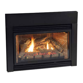
INNSBROOK FIREPLACE INSERT
Installer: Leave this manual with the appli-
ance.
Consumer: Retain this manual for future refer-
ence.
WARNING: If the information in these instruc-
tions are not followed exactly, a fire or explosion
may result causing property damage, personal
injury or loss of life.
— Do not store or use gasoline or other flamma-
ble vapors and liquids in the vicinity of this or
any other appliance.
— WHAT TO DO IF YOU SMELL GAS
•
Do not try to light any appliance.
•
Do not touch any electrical switch; do not
use any phone in your building.
•
Immediately call your gas supplier from a
neighbor's phone. Follow the gas suppli-
er's instructions.
•
If you cannot reach your gas supplier, call
the fire department.
— Installation and service must be performed by
a qualified installer, service agency or the gas
supplier.
INSTALLATION INSTRUCTIONS
OWNER'S MANUAL
AND
DIRECT VENT
GAS FIREPLACE HEATER
MODEL SERIES
DV25IN33L(N,P)-1
DV33IN33L(N,P)-1
DV35IN33L(N,P)-1
GAS-FIRED
UL FILE NO. MH30033
This appliance may be installed in an aftermarket,
permanently located, manufactured home (USA
only) or mobile home, where not prohibited by
state or local codes.
This appliance is only for use with the type of gas
indicated on the rating plate. This appliance is
not convertible for use with other gases, unless a
certified kit is used.
WARNING: If not installed, operated and main-
tained in accordance with the manufacturer's
instructions, this product could expose you to
substances in fuel or from fuel combustion which
can cause death or serious illness.
Page 1
Advertisement
Table of Contents

Related Manuals for White Mountain Hearth DV25IN33L


Summary of Contents for White Mountain Hearth DV25IN33L
-
Page 1: Installation Instructions
OWNER’S MANUAL DIRECT VENT GAS FIREPLACE HEATER MODEL SERIES DV25IN33L(N,P)-1 DV33IN33L(N,P)-1 DV35IN33L(N,P)-1 UL FILE NO. MH30033 This appliance may be installed in an aftermarket, permanently located, manufactured home (USA only) or mobile home, where not prohibited by state or local codes. -
Page 2: Table Of Contents
TABLE OF CONTENTS SECTION PAGE Important Safety Information ...3 Safety Information for Users of LP Gas ...4 Introduction ...5 Specifications ...6 Fireplace Insert Dimensions ...7 Mantle and Trim Clearances ...8 Gas Supply ...9 Venting and Installation ... 10-12 Vertical Termination ...13 Alternate ON/OFF Switch Installation ...14 Surround Panel Installation ...15 Blower Accessory Information ...16... -
Page 3: Important Safety Information
IMPORTANT SAFETY INFORMATION Before enclosing the vent pipe assembly, operate the appliance to ensure it is venting properly. DO NOT OPERATE THIS APPLIANCE WITHOUT GLASS FRONT PANEL INSTALLED • Children and adults should be alerted to the hazards of high surface temperatures and should stay away to avoid burns or clothing ignition. -
Page 4: Safety Information For Users Of Lp Gas
SAFETY INFORMATION FOR USERS OF LP GAS Propane (LP-Gas) is a flammable gas which can cause fires and explosions. In its natural state, propane is odorless and colorless. You may not know all the following safety precau- tions which can protect both you and your family from an accident. -
Page 5: Introduction
• Installation of any damaged fireplace insert or vent system component. • Modification of the fireplace insert or direct vent system. • Installation other than as instructed by Empire Comfort Systems, Inc. • Improper positioning of the logs or glass door assembly. -
Page 6: Specifications
DV25IN33L MODELS Input Btu/hr Maximum 25,000 Btu/hr Minimum 17,000 KWH (Maximum) 7.30 (Minimum) 5.00 Orifice #53 (0.0596) Air Shutter Opening Full Open DV33IN33L MODELS Input Btu/hr Maximum 33,000 Btu/hr Minimum 25,000 KWH (Maximum) 9.57 (Minimum) 7.30 Orifice #51 (0.067) Air Shutter Opening... -
Page 7: Fireplace Insert Dimensions
FIREPLACE INSERT DIMENSIONS When planning a fireplace insert installation, it’s necessary to determine: • The vent system configuration to be used. • Gas supply piping. MODEL DV25IN 19 3/8” 14 1/2” DV33IN 22 3/8” DV35IN 24 3/8” Fireplace Opening Dimensional Information/Sizing MINIMUM FIREPLACE OPENING DIMENSIONS MODEL HEIGHT... -
Page 8: Mantle And Trim Clearances
MANTLE AND TRIM CLEARANCES MINIMUM CLEARANCE TO PERPENDICULAR COMBUSTIBLE SIDE-WALL (FROM EDGE OF DOOR FRAME) Figure 3 Page 8 8” Combustible Material No greeting cards, stockings or ornamentation of any type should be placed on or attached to the fireplace. The flow of heat can ignite combustibles. -
Page 9: Gas Supply
The gas pipeline can be brought in through the right or left side of the appliance. The insert has a Flexline with shutoff valve located on the right side when facing the unit. See Figures 5 and 6. Consult the current National Fuel Gas Code, ANSI Z223.1 CAN/CGA-B149 (.1 or .2) installation code. -
Page 10: Venting And Installation
VENTING AND INSTALLATION Before beginning, remove glass door and log package from unit. Also check to make sure there is no hidden damage to the unit. Take a minute and plan out the gas, venting and elec- trical route. It is best to start with the gas line first, followed by the chimney liner and electrical supply requirements. - Page 11 VENTING AND INSTALLATION Vent System Approvals Figure 8 shows the vent termination caps and systems approved for use with these models. Approved vent system terminations are labeled for identification. 3-inch diameter listed flexible aluminum or stainless steel gas vent is used for both the incoming combustion air and exhaust vent pipes.
-
Page 12: Venting And Installation
VENTING AND INSTALLATION ROUND TERMINATION CAP (DVKI KIT) ROUND CO-LINEAR TO CO-AXIAL ADAPTOR RETAINER SCREWS MAY BE INSTALLED THROUGH THE VENT CLAMPS TO ENSURE POSITIVE SECUREMENT OF VENTING. OPTIONAL ON/OFF SWITCH LOCATION OPTIONAL LOW VOLTAGE WIRES BLOWER POWER CORD Page 12 RECTANGULAR TERMINATION CAP (DVVK3FV KIT) -
Page 13: Vertical Termination
Determining Minimum Vent Height Above the Roof. WARNING: Major U.S. building codes specify minimum chimney and/or vent height above the roof top. These minimum heights are necessary in the interest of safety. These specifica- tions are summarized in Figure 9. ROOF PITCH H (Min.) Flat to 6/12... -
Page 14: Alternate On/Off Switch Installation
ALTERNATE ON/OFF SWITCH INSTALLATION WIRING THE FIREPLACE Note: Electrical wiring must be installed by a licensed electrician. CAUTION: DISCONNECT REMOTE CONTROLS IF YOU ARE AB- SENT FOR EXTENDED TIME PERIODS. THIS WILL PREVENT ACCIDENTAL FIREPLACE OPERATION. Installation of Alternate Surround Panel ON/OFF Switch An ON/OFF switch and wire assembly are provided. -
Page 15: Surround Panel Installation
SURROUND PANEL INSTALLATION INSTALLING THE TRIM SURROUNDS Combustible materials MUST NEVER overlap onto the front face. WARNING: WHEN FINISHING THE FIREPLACE INSERT, NEVER OBSTRUCT OR MODIFY THE AIR INLET/OUTLET LOUVERS ON THE FIREPLACE IN- SERT IN ANY MANNER. NOTE: INSTALL SURROUND PANELS SO THAT THE TOP PANEL RETURN FLANGE SLIDE’S OVER THE TOP FLANGE ON... -
Page 16: Blower Accessory Information
BLOWER ACCESSORY INFORMATION The appliance, when installed must be electrically connected and grounded in accordance with local codes or, in the absence of local codes, with the current CSA C22.1 Canadian Electrical Code. U.S. Installations, follow local codes and the National Electrical Code, ANSI/NFPA No. -
Page 17: Log Placement
Before you begin: This fireplace insert is supplied with a set of seven ce- ramic fiber logs. Do not handle these logs with your bare hands. Always wear gloves to prevent skin irritation from ceramic fibers. After handling logs, wash your hands gently with soap and water to remove any traces of fiber. -
Page 18: Operating Instructions
OPERATING INSTRUCTIONS 750 Millivolt System The standing pilot (750 millivolt system) is a continuous burning pilot. The pilot remains ON even when the main burner is OFF. When you ignite the pilot, the thermopile produces millivolts (electrical current) which energizes the magnet in the gas valve. After 30 seconds to 1 minute time period you can release the gas control knob and the pilot will stay ON. -
Page 19: To Turn Off Gas
STANDING PILOT LIGHTING INSTRUCTIONS FOR YOUR SAFETY READ BEFORE LIGHTING WARNING: If you do not follow these instructions exactly, a fire or explosion may result causing property damage, personal injury or loss of life. A. This appliance has a pilot which must be lighted by hand. When lighting the pilot, follow these instructions exactly. -
Page 20: Standing Pilot Wiring
For Standing Pilot Ignition Wiring Appliance Requirements WARNING: DO NOT CONNECT 110-120 VAC TO THE GAS CONTROL VALVE OR THE APPLIANCE WILL MALFUNCTION AND THE VALVE WILL BE DE- STROYED. STANDING PILOT WIRING DIAGRAM Page 20 STANDING PILOT WIRING Optional Wall Switch Position the wall switch in the desired position on a wall. -
Page 21: Standing Pilot Troubleshooting
6. Glass soots, and/or soot deposits collected on logs. a. Flame impingement on logs incorrect. —Check and adjust log position. See Page 17. Contact Empire Comfort Systems, Inc. b. Debris around throat of main burner. —Inspect the opening at the base of the main burner. It is imperative that NO material be placed in this opening. -
Page 22: Insert Maintenance And Service
INSERT MAINTENANCE AND SERVICE Although the frequency of servicing and maintenance will depend on use and the type of installation, you should have a qualified service technician perform an appliance checkup at the beginning of each heating season. Specific guidelines regarding each appliance maintenance task are listed below. -
Page 23: Decorative Accessories
DECORATIVE ACCESSORIES The following accessory parts can be obtained from your Empire Comfort Systems dealer. If you need additional information beyond what your dealer can furnish, contact Empire Comfort Systems Inc., Nine Eighteen Freeburg Ave., Belleville, Illinois 62220. Decorative Mission Louver •... -
Page 24: Insert Parts View
INSERT PARTS VIEW Page 24 23015-3-0707... -
Page 25: Insert Parts List
INDEX NO. DV25IN33L(N,P) 22950 23309 R9188 R9192 R9195 R9194 20448 22951 22958 23303 23329 23158 23315 R3435 R3436 R2708 23159 23521 R7612 R7611 R9189 R5676 P253 P286 P214 23311 22959 22739 22973 R7577 R7578 22953 16223 M163 23009 R9257 R9258... -
Page 26: How To Order Repair Parts
Do not order bolts, screws, washers or nuts. They are standard hardware items and can be purchased at any local hardware store. Shipments contingent upon strikes, fires and all causes beyond our control. Empire Comfort Systems, Inc. Nine Eighteen Freeburg Ave. Belleville, Illinois 62222-2623 Page 26... -
Page 27: Service Notes
SERVICE NOTES 23015-3-0707 Page 27... - Page 28 Empire Comfort Systems, Inc. 918 Freeburg Ave. Belleville, IL 62220 PH: 618-233-7420 or 800-851-3153 FAX: 618-233-7097 or 800-443-8648 info@empirecomfort.com www.empirecomfort.com Page 28 23015-3-0707...