Table of Contents
Advertisement
Quick Links
Instruction Manual
D100311X012
r
Fisher
667 Diaphragm Actuators
Size 80 and 100
Contents
. . . . . . . . . . . . . . . . . . . . . . . . . . . . . . . . .
. . . . . . . . . . . . . . . . . . . . . . . . . . . . .
. . . . . . . . . . . . . . . . . . . . . . . . . . . . . . . . .
. . . . . . . . . . . . . . . . . . . . . . . . . . . . . . .
. . . . . . . . . . . . . . . . . . . . . . . . . . . . . . . . . . .
. . . . . . . . . . . . . . . . . . . . . . . . . . .
. . . . . . . . . . . . . . . . . . . . . . . . . .
. . . . . . . . . . . . . . . . . . . . . . . . . . . . . . . . .
. . . . . . . . . . . . . . . . . . . . . . . . . . . . . . . . . . . . . .
. . . . . . . . . . . . . . . . . . . . . . . . . . . . . . . . . .
. . . . . . . . . . . . . . . . . . . . . . . . . . . . . . . . .
. . . . . . . . . . . . . . . . . . . . . . . . . . . . . . .
. . . . . . . . . . . . . . . . . . . . . . . . . . . . . . . . . . .
. . . . . . . . . . . . . . . . . . . . . . . . . . . . . . . . . . .
Introduction
Scope of Manual
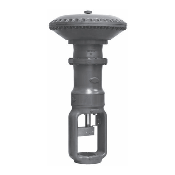
This instruction manual provides information on installation, adjustment, maintenance, and parts ordering for the
Fisher 667 actuator in sizes 80 and 100 (figure 1). Refer to separate instruction manuals for information about other
equipment and accessories used with these actuators.
www.Fisher.com
. . . . . . . . . . . . . . . . .
. . . . . . . . . . . . . . . . . . . . . . .
. . . . . . . . . . . . . . . . . .
. . . . . . . . . . . . . . . . . .
. . . . . . . . . . . . . . .
. . . . . . . . . . . . . . . . . . .
. . . . . . . . . . . . . . . . . . .
. . . . . . . . . . . . .
. . . . . . . . . . . . . . . . . . . .
. . . . . . . . . . . . . .
Figure 1. Size 80 Fisher 667 Actuator
1
1
2
2
3
4
4
5
5
6
5
6
6
7
8
12
15
17
20
21
21
22
W1950
23
23
667 Size 80 and 100 Actuators
May 2011
Advertisement
Table of Contents

Related Manuals for Emerson Fisher 667


Summary of Contents for Emerson Fisher 667
-
Page 1: Table Of Contents
This instruction manual provides information on installation, adjustment, maintenance, and parts ordering for the Fisher 667 actuator in sizes 80 and 100 (figure 1). Refer to separate instruction manuals for information about other equipment and accessories used with these actuators. -
Page 2: Description
This air pressure increases valve seat load on valve applications where additional seat‐loading is necessary. Specifications Refer to table 1 for Specifications of the 667 actuator. See the actuator nameplate for information about a specific actuator. ACTUATOR SIZE... -
Page 3: Maximum Pressure Limitations
Use pressure‐limiting or pressure‐relieving devices to prevent casing pressure from exceeding these limits. The casing and diaphragm of 667 actuators are pressure operated. This air pressure provides force to compress the spring and stroke the actuator. The following explanations describe the maximum pressure limits for 667 actuators. -
Page 4: Installation
667 Size 80 and 100 Actuators May 2011 Because the actuator has traveled its specified travel, and the diaphragm head is physically stopped from movement, the force from any additional air pressure is transmitted to the diaphragm and diaphragm casings. The amount of air pressure that can be added once the actuator has traveled to the stops is limited by the resultant adverse effects that may occur. -
Page 5: Loading Connection
Make travel adjustments when the motion observed during actuator travel is different from the travel stamped on the actuator nameplate. If the Actuator Mounting procedure was followed correctly, this adjustment should not be necessary. 667 Size 80 and 100 Actuators May 2011... -
Page 6: Size 80 Actuator Spring
667 Size 80 and 100 Actuators May 2011 When adjusting travel of a direct‐acting valve, put a slight pressure on the actuator diaphragm. This moves the valve plug off the seat, reducing the chance of damaging the valve plug or seat during adjustments. -
Page 7: Maintenance
B and the remaining adjustment required or valve travel, whichever is less. Tighten the jam nut when adjustment is complete. Maintenance WARNING Avoid personal injury or property damage from sudden release of process pressure or bursting of parts. Before performing any maintenance operations: 667 Size 80 and 100 Actuators May 2011... -
Page 8: Size 80 Actuator Maintenance
667 Size 80 and 100 Actuators May 2011 D Do not remove the actuator from the valve while the valve is still pressurized. D Always wear protective gloves, clothing, and eyewear when performing any maintenance operations to avoid personal injury. D Disconnect any operating lines providing air pressure, electric power, or a control signal to the actuator. Be sure the actuator cannot suddenly open or close the valve. - Page 9 (key 31) to the actuator stem (key 144) to prevent the stem from turning while unscrewing the stem and piston assembly (key 23). 667 Size 80 and 100 Actuators May 2011...
- Page 10 667 Size 80 and 100 Actuators May 2011 b. Using a wrench on the wrench flats near the top of the stem and piston assembly, unscrew the stem and piston assembly from the actuator stem. c. Unscrew the cap screws (key 106), and remove the cylinder (key 93) and attached parts.
- Page 11 Standard and top‐loaded constructions use the same key numbers for parts. The parts look different, but they use the same assembly and disassembly sequence. See figure 4, Size 80 Actuator Construction. STANDARD DIAPHRAGM CONSTRUCTION TOP LOADED DIAPHRAGM CONSTRUCTION 667 Size 80 and 100 Actuators May 2011 VENT ASSEMBLY (KEY 17) UPPER DIAPHRAGM...
-
Page 12: Size 100 Actuator Maintenance
667 Size 80 and 100 Actuators May 2011 10. Position the upper diaphragm casing (key 1) on the diaphragm (key 3), and align the holes. Note When you replace actuator diaphragms in the field, take care to ensure the diaphragm casing cap screws are tightened to the proper load to prevent leakage, but do not crush the material. - Page 13 (keys 144, 19, and 18). This will facilitate removal of the nut (key 24) or actuator stem connector (key 31, figure 8). 667 Size 80 and 100 Actuators May 2011...
- Page 14 667 Size 80 and 100 Actuators May 2011 Figure 5. Size 100 Actuator Construction DIAPHRAGM CASING COVER (KEY 15) UPPER DIAPHRAGM PLATE (KEY 4) UPPER DIAPHRAGM CASING (KEY 1) DIAPHRAGM (KEY 3) CAP SCREW (KEY 13) BACK UP PLATE (KEY 6)
-
Page 15: For Actuators Without The Top-Loaded Option
5. Lubricate the seal bushing O‐rings (keys 8 and 9) and the seal bushing (key 7) with lithium grease lubricant. Install the seal bushing O‐rings, seal bushing, and seal bushing retainer (keys 8, 9, 7 and 10) and secure with the cap screws (key 11). 667 Size 80 and 100 Actuators May 2011... - Page 16 667 Size 80 and 100 Actuators May 2011 6. Install the diaphragm backup plate, diaphragm retainer, diaphragm, upper diaphragm plate, and washer (keys 6, 5, 3, 4, and 37) on the actuator stem (key 144). CAUTION Install the diaphragm with the fabric side facing away from the spring. Smooth the edge of the diaphragm to avoid wrinkling and be careful that the diaphragm fold does not get pinched when the upper diaphragm casing (key 1) is installed.
-
Page 17: For Actuators With The Top-Loaded Option
Rotate the adjusting nut (key 25) to position the spring seat 305 mm (12 inches) from the end of the stem. 667 Size 80 and 100 Actuators May 2011... - Page 18 667 Size 80 and 100 Actuators May 2011 3. Install the actuator stem assembly into the yoke assembly (key 67). Place a support under the stem to position the lower end of the stem 254 mm (10 inches) above the bottom surface of the actuator (actuator‐to‐bonnet joint).
- Page 19 23. After the last cap screw is tightened to 68 NSm (50 lbfSft), all of the cap screws should be tightened again to 68 NSm (50 lbfSft) in a circular pattern around the bolt circle. 667 Size 80 and 100 Actuators May 2011...
-
Page 20: Size 80 Side-Mounted Handwheel
667 Size 80 and 100 Actuators May 2011 24. Once completed, no more tightening is recommended. 25. For actuators with a top‐mounted handwheel (see figure 9), mount the gear case assembly (key 41) on the actuator using cap screws (key 16). Install the hex nuts (key 47) and travel stop cap screw (if used) on the actuator stem extension (key 36). -
Page 21: Size 80 Hydraulic Snubber
Size 80 Hydraulic Snubber The size 80 667 actuator is available with a hydraulic snubber, as shown in figure 8, to aid vertical stability of the actuator stem movement. The snubber is adjusted by rotating the adjusting screws (key 104, figure 8) counterclockwise out of the reservoir (key 99, figure 8) to increase damping action and clockwise to decrease damping action. -
Page 22: Parts Ordering
Note Neither Emerson, Emerson Process Management, nor any of their affiliated entities assumes responsibility for the selection, use, or maintenance of any product. Responsibility for the selection, use, and maintenance of any product remains with the purchaser and end user. -
Page 23: Parts Kits
Parts kit includes keys 8, 9, and 70. Description Size 80 R667X000802 Parts List Note Part numbers are shown for recommended spares only. For part numbers not shown, contact your Emerson Process Management sales office. Actuator Description 1 Upper Diaphragm Casing 2... - Page 24 667 Size 80 and 100 Actuators May 2011 Key 18 Spring, steel RANGE ACTUATOR SIZE 0.2‐1 3‐15 0.2‐1 3‐15 0.3‐1.7 5‐25 0.4‐2 6‐30 0.4‐2 6‐30 0.3‐1.7 5‐25 0.2‐1 3‐15 0.4‐2 6‐30 Key 18 Spring, steel COMPRESSION ACTUATOR SIZE N/mm 310.8 516.5...
- Page 25 Instruction Manual D100311X012 Figure 6. Size 80 Fisher 667 Actuator TOP‐LOADED ACTUATOR DETAIL 50A8599‐C APPLY LUB/SEALANT NOTE: KEYS 243, 244, 245, AND 246 ARE NOT SHOWN. 50A8597‐D Hydraulic Snubber Size 80 Description 23 Stem & Piston Assembly 93 Cylinder 94 Cylinder Head 95...
- Page 26 667 Size 80 and 100 Actuators May 2011 Figure 7. Size 100 Fisher 667 Actuator 50A2623‐F APPLY LUB NOTES: THIS PART IS LOCATED 90_ TO FRONT OF POSITION SHOWN 2. KEYS 243 AND 244 ARE NOT SHOWN Instruction Manual 56A9820‐B TOP‐LOADED ACTUATOR DETAIL...
-
Page 27: D100311X012 May
Instruction Manual 667 Size 80 and 100 Actuators D100311X012 May 2011 Figure 8. Size 80 Fisher 667 Actuator with Side‐Mounted Handwheel and Hydraulic Snubber VIEW A SECTION B‐B VIEW A 50A8759‐C APPLY LUB/SEALANT... - Page 28 APPLY LUB Fisher is a mark owned by one of the companies in the Emerson Process Management business division of Emerson Electric Co. Emerson Process Management, Emerson, and the Emerson logo are trademarks and service marks of Emerson Electric Co. All other marks are the property of their respective owners.