Table of Contents
Advertisement
Intel® Desktop Board
D2500CC
Technical Product Specification
June 2012
Part Number: G34964-004
®
The Intel
Desktop Board D2500CC may contain design defects or errors known as errata that may cause the product to deviate from published specifications.
Current characterized errata are documented in the Intel Desktop Board D2500CC Specification Update.
Advertisement
Table of Contents

Related Manuals for Intel D2500CC


Summary of Contents for Intel D2500CC
- Page 1 Part Number: G34964-004 ® The Intel Desktop Board D2500CC may contain design defects or errors known as errata that may cause the product to deviate from published specifications. Current characterized errata are documented in the Intel Desktop Board D2500CC Specification Update.
-
Page 2: Revision History
Contact your local Intel sales office or your distributor to obtain the latest specifications before placing your product order. Intel, the Intel logo, and Intel Atom are trademarks of Intel Corporation in the U.S. and/or other countries. * Other names and brands may be claimed as the property of others. - Page 3 Board Identification Information Basic Desktop Board D2500CC Identification Information AA Revision BIOS Revision Notes G43154-303 CCDT10N.86A.0014 G43154-304 CCDT10N.86A.0014 G43154-305 CCDT10N.86A.0030 G43154-308 CCDT10N.86A.0030 G43156-301 CCDT10N.86A.0014 G43156-302 CCDT10N.86A.0030 G43156-305 CCDT10N.86A.0030 Notes: The AA number is found on a small label on the component side of the board.
- Page 4 Intel Desktop Board D2500CC Technical Product Specification...
-
Page 5: Intended Audience
Intended Audience The TPS is intended to provide detailed, technical information about the Intel Desktop Board D2500CC and its components to the vendors, system integrators, and other engineers and technicians who need this level of information. It is specifically not intended for general audiences. - Page 6 Intel Desktop Board D2500CC Technical Product Specification Other Common Notation Used after a signal name to identify an active-low signal (such as USBP0#) Gigabyte (1,073,741,824 bytes) GB/s Gigabytes per second Gb/s Gigabits per second Kilobyte (1024 bytes) Kilobit (1024 bits)
-
Page 7: Table Of Contents
1.3 Processor ..................16 ® 1.3.1 Intel D2500 Graphics Subsystem ........... 17 1.4 System Memory ................18 ® 1.5 Intel NM10 Express Chipset .............. 20 1.5.2 USB ..................22 1.5.3 SATA Support ............... 23 1.6 Real-Time Clock Subsystem ............... 23 1.7 Legacy I/O Controller ................ - Page 8 Intel Desktop Board D2500CC Technical Product Specification 2.5 Electrical Considerations ..............58 2.5.1 Fan Header Current Capability ..........58 2.5.2 Add-in Board Considerations ........... 58 2.6 Thermal Considerations ..............58 2.6.1 Passive Heatsink Design in a Passive System Environment ..60 2.7 Power Consumption ................
- Page 9 12. Connection Diagram for Front Panel Header ......... 52 13. Connection Diagram for Front Panel USB 2.0 Header ......54 14. Connection Diagram for Front Panel USB 2.0 Header with Intel Z-USB Solid-State Drive or Compatible Device Support ........54 15.
- Page 10 22. Front Panel Audio Header for AC ’97 Audio ........... 48 23. Front Panel USB 2.0 Headers ............. 48 24. Front Panel USB Header with Intel Z-U130 USB Solid-State Drive or Compatible Device Support ..............48 25. Internal S/PDIF Header ..............49 26.
-
Page 11: Product Description
Product Description Overview 1.1.1 Feature Summary Table 2 summarizes the major features of Intel Desktop Board D2500CC. Table 2. Feature Summary Form Factor Mini-ITX (6.7 inches by 6.7 inches [170 millimeters by 170 millimeters]) compatible with microATX ® Processor Passively-cooled, soldered-down Dual-Core Intel Atom™... - Page 12 Intel Desktop Board D2500CC Technical Product Specification Table 2. Feature Summary (continued) ® • Intel BIOS (resident in the SPI Flash device) BIOS • Support for Advanced Configuration and Power Interface (ACPI), Plug and Play, and SMBIOS • Suspend to RAM support...
-
Page 13: Board Layout
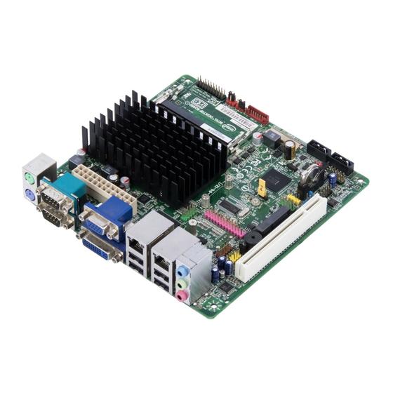
Product Description 1.1.2 Board Layout Figure 1 shows the location of the major components. Figure 1. Major Board Components Table 3 lists the components identified in Figure 1. -
Page 14: Board Components Shown In Figure 1
BIOS setup configuration jumper block PCI Express Full-/Half-Mini Card slot Conventional PCI bus add-in card connector Piezoelectric speaker Parallel port header Front panel audio header Front panel USB header with Intel Z-U130 USB Solid-State Drive or compatible device support (brown-colored) -
Page 15: Block Diagram
Product Description 1.1.3 Block Diagram Figure 2 is a block diagram of the major functional areas. Figure 2. Block Diagram... -
Page 16: Online Support
025414.htm Integration information http://www.intel.com/support/go/buildit Processor The board has a passively-cooled, soldered-down Dual-Core Intel Atom processor with integrated graphics and integrated memory controller. NOTE The board is designed to be passively cooled in a properly ventilated chassis. Chassis venting locations are recommended above the processor heatsink area for maximum heat dissipation effectiveness. -
Page 17: Intel ® D2500 Graphics Subsystem
® 1.3.1 Intel D2500 Graphics Subsystem ® 1.3.1.1 Intel Graphics Media Accelerator 3600 Graphics ® Controller (Intel GMA) ® The Intel GMA 3600 graphics controller features the following: • 400 MHz core frequency High quality texture engine • DX9.3* and OpenGL* 3.0 compliant ... -
Page 18: System Memory
Intel Desktop Board D2500CC Technical Product Specification System Memory The board has two 204-pin DDR3 SO-DIMM sockets and supports the following memory features: • DDR3 SDRAM SO-DIMMs with gold-plated contacts Unbuffered, single-sided or double-sided DIMMs • 4 GB maximum total system memory •... -
Page 19: Memory Channel And So-Dimm Configuration
Product Description Figure 3 illustrates the memory channel and SO-DIMM configuration. Figure 3. Memory Channel and SO-DIMM Configuration... -
Page 20: Intel ® Nm10 Express Chipset
Intel NM10 Express Chipset The Intel NM10 Express Chipset provides interfaces to the processor and the USB, SATA, LPC, LAN, PCI, and PCI Express interfaces. The Intel NM10 Express Chipset is a centralized controller for the board’s I/O paths. NOTE The board is designed to be passively cooled in a properly ventilated chassis. -
Page 21: Configuration Modes
• “Screen brightness” adjustment slider NOTE Support for flat panel display configuration complies with the following: ® 1. Internal flat panel display settings are not exposed through Intel Integrator ® Toolkit or Intel Integrator Assistant GUIs. 2. Internal flat panel display settings will not be overwritten by loading BIOS setup defaults. -
Page 22: Usb
• parameters, if necessary. NOTE Support for flat panel display configuration complies with the following: ® 1. Internal flat panel display settings are not exposed through Intel Integrator ® Toolkit or Intel Integrator Assistant GUIs. 2. Internal flat panel display settings will not be overwritten by loading BIOS setup defaults. -
Page 23: Sata Support
Product Description For information about Refer to The location of the USB connectors on the back panel Figure 9, page 41 The location of the front panel USB headers Figure 11, page 43 1.5.3 SATA Support The board provides two SATA interface connectors that support one device per connector. -
Page 24: Legacy I/O Controller
Intel Desktop Board D2500CC Technical Product Specification Legacy I/O Controller The Legacy I/O Controller provides the following features: Two serial port headers • Two serial port connectors on the back panel • One parallel port header with Enhanced Parallel Port (EPP) support •... -
Page 25: Lan Subsystem
Full device driver compatibility • PCI Express power management support • 1.8.2 LAN Subsystem Software and Drivers LAN software and drivers are available from Intel’s World Wide Web site. For information about Refer to Obtaining LAN software and drivers http://downloadcenter.intel.com... -
Page 26: Rj-45 Lan Connector With Integrated Leds
Intel Desktop Board D2500CC Technical Product Specification 1.8.3 RJ-45 LAN Connector with Integrated LEDs Two LEDs are built into the RJ-45 LAN connectors (shown in Figure 4). Figure 4. LAN Connector LED Locations Table 5 describes the LED states when the board is powered up and the Ethernet LAN subsystem is operating. -
Page 27: Audio Subsystem
The back panel audio jacks are capable of retasking according to the user’s definition, or can be automatically switched depending on the recognized device type. Front panel Intel HD Audio and AC ’97 audio support. • 3-port analog audio out stack. -
Page 28: Audio Subsystem Software
Intel Desktop Board D2500CC Technical Product Specification 1.9.1 Audio Subsystem Software Audio software and drivers are available from Intel’s World Wide Web site. For information about Refer to Obtaining audio software and drivers Section 1.2, page 16 1.9.2 Audio Connectors and Headers The board contains audio connectors and headers on both the back panel and the component side of the board. -
Page 29: 1.10 Hardware Management Subsystem
Product Description 1.10 Hardware Management Subsystem The hardware management features enable the board to be compatible with the Wired for Management (WfM) specification. The board has several hardware management features, including the following: Thermal monitoring • Voltage monitoring • 1.10.1 Hardware Monitoring The hardware monitoring and fan control subsystem is based on the Winbond W83627DHG-P device, which supports the following:... -
Page 30: Thermal Monitoring
Intel Desktop Board D2500CC Technical Product Specification 1.10.2 Thermal Monitoring Figure 6 shows the locations of the thermal sensors and fan header. Item Description Remote thermal sensor DTS, located on the processor die System fan header Figure 6. Thermal Sensors and Fan Header... -
Page 31: 1.11 Power Management
Product Description 1.11 Power Management Power management is implemented at several levels, including: Software support through Advanced Configuration and Power Interface (ACPI) • Hardware support: • Power connector Fan header LAN wake capabilities Instantly Available PC technology ... -
Page 32: Power States And Targeted System Power
Intel Desktop Board D2500CC Technical Product Specification 1.11.1.1 System States and Power States Under ACPI, the operating system directs all system and device power state transitions. The operating system puts devices in and out of low-power states based on user preferences and knowledge of how devices are being used by applications. -
Page 33: Wake-Up Devices And Events
Product Description 1.11.1.2 Wake-up Devices and Events Table 9 lists the devices or specific events that can wake the computer from specific states. Table 9. Wake-up Devices and Events Devices/events that wake up the system… …from this sleep state Note 1) Power switch S3, S4, S5 (Note 1) -
Page 34: Hardware Support
Intel Desktop Board D2500CC Technical Product Specification 1.11.2 Hardware Support The board provides several power management hardware features, including: Power connector • Fan header • LAN wake capabilities • Instantly Available PC technology • Wake from USB • Wake from PS/2 devices •... -
Page 35: Instantly Available Pc Technology
Product Description 1.11.2.3 Instantly Available PC Technology Instantly Available PC technology enables the board to enter the ACPI S3 (Suspend-to- RAM) sleep-state. While in the S3 sleep-state, the computer will appear to be off (the hard drive(s) and fan will power off, the front panel LED will blink). When signaled by a wake-up device or event, the system quickly returns to its last known state. -
Page 36: Location Of The Standby Power Indicator Led
Intel Desktop Board D2500CC Technical Product Specification 1.11.2.9 +5 V Standby Power Indicator LED The +5 V standby power indicator LED shows that power is still present even when the computer appears to be off. Figure 7 shows the location of the standby power indicator LED. -
Page 37: Technical Reference
Technical Reference Memory Map 2.1.1 Addressable Memory The board utilizes 4 GB of addressable system memory. Typically the address space that is allocated for Conventional PCI bus add-in cards, PCI Express configuration space, BIOS (SPI Flash), and chipset overhead resides above the top of DRAM (total system memory). -
Page 38: Detailed System Memory Address Map
Intel Desktop Board D2500CC Technical Product Specification The amount of installed memory that can be used will vary based on add-in cards and BIOS settings. Figure 8 shows a schematic of the system memory map. All installed system memory can be used when there is no overlap of system addresses. -
Page 39: System Memory Map
Technical Reference Table 10 lists the system memory map. Table 10. System Memory Map Address Range Address Range (decimal) (hex) Size Description 1024 K - 4194304 K 100000 - FFFFFFFF 4095 MB Extended memory 960 K - 1024 K F0000 - FFFFF 64 KB Runtime BIOS 896 K - 960 K... -
Page 40: Connectors And Headers
Intel Desktop Board D2500CC Technical Product Specification Connectors and Headers CAUTION Only the following connectors/headers have overcurrent protection: Back panel and front panel USB, VGA, serial, and PS/2. The other internal connectors/headers are not overcurrent protected and should connect only to devices inside the computer’s chassis, such as fans and internal peripherals. -
Page 41: Back Panel
Technical Reference 2.2.1 Back Panel 2.2.1.1 Back Panel Connectors Figure 9 shows the location of the back panel connectors. Item Description PS/2 mouse port PS/2 keyboard port Serial port connector Serial port connector VGA connector DVI-I connector LAN port USB 2.0 ports LAN port USB 2.0 ports Line in... -
Page 42: I/O Shield Reference Diagram
Intel Desktop Board D2500CC Technical Product Specification 2.2.1.2 I/O Shield The I/O shield provided with the board allows access to all back panel connectors and is compatible with standard mini-ITX and microATX chassis. As an added benefit for system configurations with wireless PCI Express Mini Card solutions, the I/O shield also provides pre-cut holes for user installation of up to three external wireless antennas. -
Page 43: Component-Side Connectors And Headers
Technical Reference 2.2.2 Component-side Connectors and Headers Figure 11 shows the locations of the component-side connectors and headers. Figure 11. Component-side Connectors and Headers... -
Page 44: Component-Side Connectors And Headers Shown In Figure 11
Front Panel Wireless Activity LED header Serial port header PCI Express Full-/Half-Mini Card slot Conventional PCI bus add-in card connector Parallel port header Front panel audio header Front panel USB header with Intel Z-U130 USB Solid-State Drive or compatible device support (brown-colored) -
Page 45: Tpm Header
Technical Reference 2.2.2.1 Signal Tables for the Connectors and Headers Table 12. TPM Header Signal Name Signal Name CK_33M_TPM_DIP Ground LFRAME# Key (no pin) PLTRST# No connection LAD3 LAD2 +3.3 V LAD1 LAD0 Ground No connection No connection +3.3 VSB TPM_SERRQ Ground TPM_CLKRUN#... -
Page 46: Lvds Data Connector
Intel Desktop Board D2500CC Technical Product Specification Table 14. LVDS Data Connector Signal Name Signal Name EVEN_Lane3_P EVEN_Lane3_N EDID_3.3 V EVEN_Lane2_P LCD_GND EVEN_Lane2_N LCD_GND EVEN_Lane1_P LCD_GND EVEN_Lane1_N EVEN_CLK_P EVEN_Lane0_P EVEN_CLK_N EVEN_Lane0_N BKLT_GND ODD_Lane3_P BKLT_GND ODD_Lane3_N BKLT_GND ODD_Lane2_P EDID_CLK ODD_Lane2_N BKLT_ENABLE... -
Page 47: Fpd Brightness Connector
Technical Reference Table 16. FPD Brightness Connector Signal Name Description BKLT_EN Backlight enable BKLT_PWM Backlight control BKLT_PWR (5 V/12 V) Backlight inverter power BKLT_PWR (5 V/12 V) Backlight inverter power BKLT_GND/Brightness_GND Ground (shared) BKLT_GND/Brightness_GND Ground (shared) Brightness_Up Panel brightness increase Brightness_Down Panel brightness decrease Table 17. -
Page 48: Front Panel Wireless Activity Led Header
Signal Name +5 VDC +5 VDC Ground Ground KEY (no pin) No Connect Table 24. Front Panel USB Header with Intel Z-U130 USB Solid-State Drive or Compatible Device Support Signal Name Signal Name +5 VDC Ground KEY (no pin) LED#... -
Page 49: Parallel Port Header
Technical Reference Table 25. Internal S/PDIF Header Signal Name Description Ground SPDIF_OUT S/PDIF signal from the codec Key (no pin) Key (no pin) +5V_DC 5 V power (for optical/TOSLINK module) Table 26. Parallel Port Header Standard Signal Name ECP Signal Name EPP Signal Name STROBE# STROBE#... -
Page 50: Add-In Card Connectors
Intel Desktop Board D2500CC Technical Product Specification 2.2.2.2 Add-in Card Connectors The board has the following add-in card connectors: PCI Express Full-/Half-Mini Card slot • Conventional PCI bus connector (with riser card support for up to two PCI cards) •... -
Page 51: Power Connector
Technical Reference 2.2.2.3 Power Supply Connector The board has a 2 x 12 power connector (see Table 27). This board requires a TFX12V or SFX12V power supply. Table 27. Power Connector Signal Name Signal Name +3.3 V +3.3 V +3.3 V -12 V Ground Ground... -
Page 52: Connection Diagram For Front Panel Header
Intel Desktop Board D2500CC Technical Product Specification 2.2.2.4 Front Panel Header This section describes the functions of the front panel header. Table 28 lists the signal names of the front panel header. Figure 12 is a connection diagram for the front panel header. -
Page 53: States For A One-Color Power Led
Technical Reference 2.2.2.4.1 Hard Drive Activity LED Header Pins 1 and 3 can be connected to an LED to provide a visual indicator that data is being read from or written to a hard drive. 2.2.2.4.2 Reset Switch Header Pins 5 and 7 can be connected to a momentary single pole, single throw (SPST) type switch that is normally open. -
Page 54: Connection Diagram For Front Panel Usb 2.0 Header
Use only a front panel USB connector that conforms to the USB 2.0 specification for • high-speed USB devices. Figure 13. Connection Diagram for Front Panel USB 2.0 Header Figure 14. Connection Diagram for Front Panel USB 2.0 Header with Intel Z-USB Solid-State Drive or Compatible Device Support... -
Page 55: Bios Configuration Jumper Block
Technical Reference BIOS Configuration Jumper Block CAUTION Do not move the jumper with the power on. Always turn off the power and unplug the power cord from the computer before changing a jumper setting. Otherwise, the board could be damaged. Figure 15 shows the location of the jumper block. -
Page 56: Bios Configuration Jumper Settings
Intel Desktop Board D2500CC Technical Product Specification Table 30. BIOS Configuration Jumper Settings Jumper Function/Mode Setting Configuration Normal The BIOS uses current configuration information and passwords for booting. Configure After the POST runs, Setup runs automatically. The maintenance menu is displayed. -
Page 57: Mechanical Considerations
Technical Reference Mechanical Considerations 2.4.1 Form Factor The board is designed to fit into a mini-ITX or microATX form-factor chassis. Figure 16 illustrates the mechanical form factor for the board. Dimensions are given in inches [millimeters]. The outer dimensions are 6.7 inches by 6.7 inches [170 millimeters by 170 millimeters]. -
Page 58: Electrical Considerations
Failure to ensure appropriate airflow may result in reduced performance of both the processor and/or voltage regulator or, in some instances, damage to the board. For a list of chassis that have been tested with Intel Desktop Boards please refer to the following website: http://www3.intel.com/cd/channel/reseller/asmo-na/eng/tech_reference/53211.htm... -
Page 59: Localized High Temperature Zones
Description Processor voltage regulator area Intel Atom processor Intel NM10 Express Chipset Figure 17. Localized High Temperature Zones Table 32 provides maximum case temperatures for the board components that are sensitive to thermal changes. The operating temperature, current load, or operating frequency could affect case temperatures. -
Page 60: Passive Heatsink Design In A Passive System Environment
This information should be used in conjunction with the Thermal and Mechanical Design Guide (TMDG) published for the Intel Atom processor D2000 series. The TMDG contains detailed package information and thermal mechanical specifications for the processors. -
Page 61: Chassis Design Guideline
Technical Reference 2.6.1.2 Thermal Specifications Guideline Terms Requirements ≤ 50 °C ≤ 100 °C Ψ ≤ 3.85 °C/W Honeywell PCM45F 10 W external ≤ 35 °C 2.6.1.3 Heatsink Design Guideline (Note) Maximum heatsink size 87 x 52 x 29 mm Heatsink mass ≤... -
Page 62: Fan Location Guide For Chassis Selection (Chassis Orientation Is Not Restricted)
Intel Desktop Board D2500CC Technical Product Specification Figure 18. Fan Location Guide for Chassis Selection (Chassis Orientation is Not Restricted) For all chassis configurations, the heatsink performance parameter, Ψ should be less than 3.85 °C/W. The detail thermal measurement metrology is described in the TMSDG. -
Page 63: Power Consumption
3.5-inch SATA hard disk drive, running Microsoft Windows Vista Home Basic • Load: continuous read/write benchmark • Intel Z-U130 USB Solid-State Drive or compatible device on the USB flash drive header Load: continuous read/write benchmark Wireless card on PCI Express Full-/Half-Mini Card slot, connected via 802.11n •... -
Page 64: Reliability
Method I Case 1 50% electrical stress, 55 ºC ambient. The MTBF prediction is used to estimate repair rates and spare parts requirements. The MTBF data was calculated from predicted data at 55 ºC. The Intel Desktop Board D2500CC has an MTBF of at least 314,073 hours. -
Page 65: Overview Of Bios Features
Overview of BIOS Features Introduction The board uses an Intel BIOS that is stored in the Serial Peripheral Interface Flash Memory (SPI Flash) and can be updated using a disk-based program. The SPI Flash contains the BIOS Setup program, POST, the PCI auto-configuration utility, LAN EEPROM information, and Plug and Play support. -
Page 66: Bios Flash Memory Organization
Intel Desktop Board D2500CC Technical Product Specification Table 36 lists the BIOS Setup program menu features. Table 36. BIOS Setup Program Menu Bar Maintenance Main Advanced Security Power Boot Exit Clears Displays Configures Sets Configures Selects boot Saves or passwords and... -
Page 67: System Management Bios (Smbios)
Overview of BIOS Features System Management BIOS (SMBIOS) SMBIOS is a Desktop Management Interface (DMI) compliant method for managing computers in a managed network. The main component of SMBIOS is the Management Information Format (MIF) database, which contains information about the computing system and its components. -
Page 68: Legacy Usb Support
Legacy USB support from the BIOS is no longer used. 7. Additional USB legacy feature options can be accessed by using Intel Integrator Toolkit. To install an operating system that supports USB, verify that Legacy USB support in the BIOS Setup program is set to Enabled and follow the operating system’s... -
Page 69: Bios Updates
Overview of BIOS Features BIOS Updates The BIOS can be updated using either of the following utilities, which are available on the Intel World Wide Web site: ® • Intel Express BIOS Update utility, which enables automated updating while in the Windows environment. -
Page 70: Custom Splash Screen
Integrator’s Toolkit that is available from Intel can be used to create a custom splash screen. NOTE If you add a custom splash screen, it will share space with the Intel branded logo. Refer to For information about Intel Integrator Toolkit http://developer.intel.com/design/motherbd/software/itk/... -
Page 71: Booting Without Attached Devices
Overview of BIOS Features 3.7.3 Booting Without Attached Devices For use in embedded applications, the BIOS has been designed so that after passing the POST, the operating system loader is invoked even if the following devices are not present: Video adapter •... -
Page 72: Bios Boot Optimizations
It is possible to optimize the boot process to the point where the system boots so quickly that the Intel logo screen (or a custom logo splash screen) will not be seen. Monitors and hard disk drives with minimum initialization times can also contribute to a boot time that might be so fast that necessary logo screens and POST messages cannot be seen. -
Page 73: Bios Security Features
Overview of BIOS Features BIOS Security Features The BIOS includes security features that restrict access to the BIOS Setup program and who can boot the computer. A supervisor password and a user password can be set for the BIOS Setup program and for booting the computer, with the following restrictions: The supervisor password gives unrestricted access to view and change all the Setup •... - Page 74 Intel Desktop Board D2500CC Technical Product Specification...
-
Page 75: Board Status And Error Messages
Board Status and Error Messages BIOS Beep Codes The BIOS uses audible beep codes to signal status messages and error messages indicating recoverable errors that occur during the POST. The beep codes are listed in Table 41. These beep codes can be heard through a speaker attached to the board’s line out audio jack (see Figure 5, B on page 28). -
Page 76: Front-Panel Power Led Blink Codes
Intel Desktop Board D2500CC Technical Product Specification Front-panel Power LED Blink Codes Whenever a recoverable error occurs during POST, the BIOS causes the board’s front panel power LED to blink an error message describing the problem (see Table 42). Table 42. Front-panel Power LED Blink Codes... -
Page 77: Port 80H Post Codes
Board Status and Error Messages Port 80h POST Codes During the POST, the BIOS generates diagnostic progress codes (POST codes) to I/O port 80h. If the POST fails, execution stops and the last POST code generated is left at port 80h. This code is useful for determining the point where an error occurred. Displaying the POST codes requires a PCI bus add-in card, often called a POST card. -
Page 78: Port 80H Post Codes
Intel Desktop Board D2500CC Technical Product Specification Table 45. Port 80h POST Codes Port 80 Code Progress Code Enumeration ACPI S States 0x00,0x01,0x02,0x03,0x04,0x05 Entering S0, S2, S3, S4, or S5 state 0x10,0x20,0x30 Resuming from S2, S3, S4, or S5 state... - Page 79 Board Status and Error Messages Table 45. Port 80h POST Codes (continued) Port 80 Code Progress Code Enumeration CPU DXE Phase 0x47 CPU DXE Phase begin 0x48 Refresh memory space attributes according to MTRRs 0x49 Load the microcode if needed 0x4A Initialize strings to HII database 0x4B...
- Page 80 Intel Desktop Board D2500CC Technical Product Specification Table 45. Port 80h POST Codes (continued) Port 80 Code Progress Code Enumeration Keyboard (PS/2 or USB) 0x90 Resetting keyboard 0x91 Disabling the keyboard 0x92 Detecting the presence of the keyboard 0x93 Enabling the keyboard...
-
Page 81: Typical Port 80H Post Sequence
Board Status and Error Messages Table 46. Typical Port 80h POST Sequence POST Code Description Detecting presence of memory DIMMs Configuring memory Testing memory Loading recovery capsule Entered DXE phase Enumerating PCI buses Allocating resourced to PCI bus Detecting the presence of the keyboard Resetting keyboard Clearing keyboard input buffer Keyboard Self Test... - Page 82 Intel Desktop Board D2500CC Technical Product Specification...
-
Page 83: Regulatory Compliance And Battery Disposal Information
Electromagnetic Compatibility (EMC) standards • Product certification markings • 5.1.1 Safety Standards Intel Desktop Board D2500CC complies with the safety standards stated in Table 47 when correctly installed in a compatible host system. Table 47. Safety Standards Standard Title CSA/UL 60950-1 Information Technology Equipment –... -
Page 84: European Union Declaration Of Conformity Statement
European Union Declaration of Conformity Statement ® We, Intel Corporation, declare under our sole responsibility that the product Intel Desktop Board D2500CC is in conformity with all applicable essential requirements necessary for CE marking, following the provisions of the European Council Directive 2004/108/EC (EMC Directive), 2006/95/EC (Low Voltage Directive), and 2002/95/EC (ROHS Directive). -
Page 85: Product Ecology Statements
请参考http://www.intel.com/intel/other/ehs/product_ecology 了解此计划的详情,包括涉及 产品之范围、回收地点、运送指导、条款和条件等。 Deutsch Als Teil von Intels Engagement für den Umweltschutz hat das Unternehmen das Intel Produkt-Recyclingprogramm implementiert, das Einzelhandelskunden von Intel Markenprodukten ermöglicht, gebrauchte Produkte an ausgewählte Standorte für ordnungsgemäßes Recycling zurückzugeben. Details zu diesem Programm, einschließlich der darin eingeschlossenen Produkte, verfügbaren Standorte, Versandanweisungen, Bedingungen usw., finden Sie auf der... - Page 86 Français Dans le cadre de son engagement pour la protection de l'environnement, Intel a mis en œuvre le programme Intel Product Recycling Program (Programme de recyclage des produits Intel) pour permettre aux consommateurs de produits Intel de recycler les produits usés en les retournant à...
-
Page 87: Emc Regulations
şartlar v.s dahil bütün ayrıntılarını ögrenmek için lütfen http://www.intel.com/intel/other/ehs/product_ecology Web sayfasına gidin. 5.1.4 EMC Regulations Intel Desktop Board D2500CC complies with the EMC regulations stated in Table 48 when correctly installed in a compatible host system. Table 48. EMC Regulations Regulation Title... - Page 88 • Consult the dealer or an experienced radio/TV technician for help. Any changes or modifications to the equipment not expressly approved by Intel Corporation could void the user’s authority to operate the equipment. Tested to comply with FCC standards for home or office use.
- Page 89 Regulatory Compliance and Battery Disposal Information Japan VCCI Statement Japan VCCI Statement translation: This is a Class B product based on the standard of the Voluntary Control Council for Interference from Information Technology Equipment (VCCI). If this is used near a radio or television receiver in a domestic environment, it may cause radio interference.
-
Page 90: Energy Star* 5.0, E-Standby, And Erp Compliance
Intel Desktop Board D2500CC Technical Product Specification 5.1.5 ENERGY STAR* 5.0, e-Standby, and ErP Compliance Intel Desktop Board D2500CC meets the ENERGY STAR requirements listed in Table 49 when used in corresponding system configurations. Table 49. ENERGY STAR Requirements Typical... -
Page 91: Regulatory Compliance Marks (Board Level)
Regulatory Compliance and Battery Disposal Information 5.1.6 Regulatory Compliance Marks (Board Level) Intel Desktop Board D2500CC has the regulatory compliance marks shown in Table 50. Table 50. Regulatory Compliance Marks Description Mark UL joint US/Canada Recognized Component mark. Includes adjacent UL file number for Intel Desktop Boards: E210882. -
Page 92: Battery Disposal Information
Intel Desktop Board D2500CC Technical Product Specification Battery Disposal Information CAUTION Risk of explosion if the battery is replaced with an incorrect type. Batteries should be recycled where possible. Disposal of used batteries must be in accordance with local environmental regulations. - Page 93 Regulatory Compliance and Battery Disposal Information PRECAUCIÓN Existe peligro de explosión si la pila no se cambia de forma adecuada. Utilice solamente pilas iguales o del mismo tipo que las recomendadas por el fabricante del equipo. Para deshacerse de las pilas usadas, siga igualmente las instrucciones del fabricante.
- Page 94 Intel Desktop Board D2500CC Technical Product Specification AWAS Risiko letupan wujud jika bateri digantikan dengan jenis yang tidak betul. Bateri sepatutnya dikitar semula jika boleh. Pelupusan bateri terpakai mestilah mematuhi peraturan alam sekitar tempatan. OSTRZEŻENIE Istnieje niebezpieczeństwo wybuchu w przypadku zastosowania niewłaściwego typu baterii.
- Page 95 Regulatory Compliance and Battery Disposal Information...
- Page 96 Intel Desktop Board D2500CC Technical Product Specification...