Table of Contents
Advertisement
Advertisement
Table of Contents

Related Manuals for Intel D2500CC


Summary of Contents for Intel D2500CC
- Page 1 Intel® Desktop Board D2500CC Product Guide Order Number: G34962-001...
-
Page 2: Revision History
Intel may make changes to specifications and product descriptions at any time, without notice. Intel Desktop Board D2500CC may contain design defects or errors known as errata which may cause the product to deviate from published specifications. Current characterized errata are available on request. -
Page 3: Intended Audience
The suitability of this product for other PC or embedded non-PC applications or other environments, such as medical, industrial, alarm systems, test equipment, etc. may not be supported without further evaluation by Intel. Document Organization The chapters in this Product Guide are arranged as follows:... - Page 4 Intel Desktop Board D2500CC Product Guide Terminology The table below gives descriptions to some common terms used in the product guide. Term Description Gigabyte (1,073,741,824 bytes) Gigahertz (one billion hertz) Kilobyte (1024 bytes) Megabyte (1,048,576 bytes) Megabit (1,048,576 bits) Megahertz (one million hertz)
-
Page 5: Table Of Contents
Installing and Removing Memory................28 Connecting SATA Drives..................29 Installing a PCI Express Mini Card ................30 ® Installing an Intel Z-U130 USB Solid-State Drive or Compatible Device ....32 Connecting to the Internal Headers ..............33 Front Panel Audio Header ................34 Front Panel USB 2.0 Headers................34 Parallel Port Header ..................35... - Page 6 Intel Desktop Board D2500CC Product Guide Setting the BIOS Configuration Jumper ..............40 Clearing Passwords ..................41 Replacing the Battery ..................42 3 Updating the BIOS ® Updating the BIOS with the Intel Express BIOS Update Utility.........47 Updating the BIOS Using the F7 Function Key ............48 Updating the BIOS with the Iflash Memory Update Utility .........48...
- Page 7 14. Connecting Power Supply Cables ..............39 15. BIOS Configuration Jumper Block..............40 16. Removing the Battery ...................46 17. Intel Desktop Board D2500CC China RoHS Material Self Declaration Table ....58 Tables 1. Feature Summary..................9 2. Intel Desktop Board D2500CC Components ............12 3.
- Page 8 Intel Desktop Board D2500CC Product Guide viii...
-
Page 9: Desktop Board Features
HD Audio) and AC ’97 Audio. Included are: • Back panel audio connectors • Onboard S/PDIF digital audio header • Front panel microphone/headphone header with support for Intel HD Audio or AC ’97 Audio Legacy I/O Controller (Nuvoton* W83677HG-I) that provides: Legacy I/O •... -
Page 10: Operating System Support
• Support for Advanced Configuration and Power Interface (ACPI) PC Technology • Wake on USB, PCI, PCI Express, LAN, serial, PS/2, and front panel For more information on Intel Desktop Board D2500CC consult the following online resources: To find information Visit this World Wide Web site: about…... -
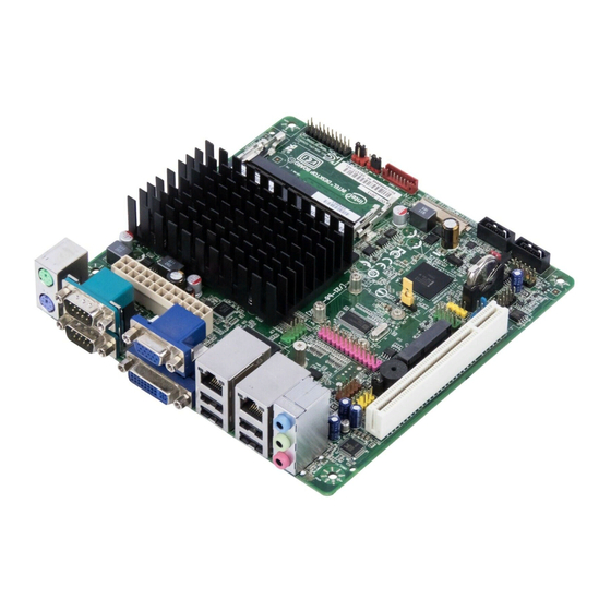
Page 11: Desktop Board Components
Desktop Board Features Desktop Board Components Figure 1 shows the location of the major components on Intel Desktop Board D2500CC. Figure 1. Intel Desktop Board D2500CC Components... -
Page 12: Intel Desktop Board D2500Cc Components
Front panel wireless activity LED header Serial port header BIOS configuration jumper block PCI Express Full-Mini Card slot PCI bus connector Piezoelectric speaker Parallel port header Front panel audio header USB front panel header with Intel Z-U130 USB Solid-State Drive (or compatible device) support... -
Page 13: Processor
Desktop Board Features Processor Intel Desktop Board D2500CC includes a passively-cooled, dual-core Intel Atom processor with integrated graphics and memory controller. The processor is soldered to the Desktop Board and is not customer upgradeable. NOTE The board is designed to be passively cooled in a properly ventilated chassis. Chassis venting locations are recommended above the processor heatsink area for maximum heat dissipation effectiveness. -
Page 14: Graphics Support
Flat panel display brightness connector • Backlight inverter voltage selection header The connectors and headers are shown in Figure 2. For more information on flat panel display support, refer to the Intel Desktop Board D2500CC Technical Product Specification located at http://www.intel.com/products/motherboard/index.htm. -
Page 15: External Graphics
(see Figure 1, X). ® Intel NM10 Express Chipset The Intel NM10 Express Chipset is a centralized controller for the board’s I/O paths. For more information about the Intel NM10 Express Chipset, go to http://www.intel.com/products/chipsets/index.htm?iid=prod+prod_chipset. Onboard Audio Subsystem The onboard audio subsystem supports both Intel HD Audio and AC ’97 Audio. The subsystem is based on the following components: •... -
Page 16: Back Panel Audio Connectors
Intel Desktop Board D2500CC Product Guide • Front panel audio header (supports both Intel HD Audio and AC ’97 Audio), including functionality for: ― Line out (headphones/speaker) ― Microphone in The board supports 2-channel audio output from the back panel analog ports with jack detection as indicated in Table 3. -
Page 17: Legacy Input/Output (I/O) Controller
The LAN subsystem consists of the following: • Intel NM10 Express Chipset • Two Intel 82574L Gigabit Ethernet Controllers for 10/100/1000 Mb/s Ethernet LAN connectivity • Two RJ-45 LAN connectors with integrated status LEDs Additional features of the LAN subsystem include: •... -
Page 18: Usb 2.0 Support
USB 2.0 headers). One of the front panel USB headers supports an Intel Z-U130 USB Solid-State Drive or compatible device. The USB 2.0 ports are compatible with USB 1.1 devices. USB 1.1 devices will function normally at USB 1.1 speeds. -
Page 19: Bios
Desktop Board Features BIOS The BIOS provides the Power-On Self-Test (POST), the BIOS Setup program, the PCI and SATA auto-configuration utilities, and the video BIOS. PCI/PCI Express Auto Configuration If you install a PCI Card or a PCI Express Mini Card in your computer, the PCI/PCI Express auto-configuration utility in the BIOS automatically detects and configures the resources (IRQs, DMA channels, and I/O space) for that add-in card. -
Page 20: Power Management Features
Intel Desktop Board D2500CC Product Guide Power Management Features Power management is implemented at several levels, including: • Software support through the Advanced Configuration and Power Interface (ACPI) • Hardware support: ― Power connector ― Fan header ― +5 V standby power indicator LED ―... -
Page 21: Location Of The Standby Power Indicator
Desktop Board Features Figure 5. Location of the Standby Power Indicator For more information on standby current requirements for the Desktop Board, refer to the Technical Product Specification on the Intel Desktop D2500CC web page at http://www.intel.com/products/motherboard/index.htm. Instantly Available PC Technology Instantly Available PC technology enables the board to enter the ACPI S3 (Suspend-to- RAM) sleep-state. -
Page 22: Battery
Intel Desktop Board D2500CC Product Guide LAN Wake Capabilities The board’s LAN wake capabilities enable remote wake-up of the computer through a network. The LAN subsystem network adapter monitors network traffic at the Media Independent Interface. The board supports LAN wake capabilities with ACPI in the following ways: •... -
Page 23: Installing And Replacing Desktop Board Components
Install and remove system memory • Connect SATA drives • Install a PCI Express Mini Card • Install an Intel Z-U130 USB Solid-State Drive or compatible device • Connect to internal headers • Connect system fan and power supply cables •... - Page 24 All responsibility for determining the adequacy of any thermal or system design remains solely with the reader. Intel makes no warranties or representations that merely following the instructions presented in this document will result in a system with adequate thermal performance.
-
Page 25: Installation Precautions
Installing and Replacing Desktop Board Components Installation Precautions When you install and test the Intel Desktop Board, observe all warnings and cautions in the installation instructions. To avoid injury, be careful of: • Sharp pins on connectors or headers •... -
Page 26: Installing The I/O Shield
Intel Desktop Board D2500CC Product Guide Installing the I/O Shield The Desktop Board comes with an I/O shield. When installed in the chassis, the shield blocks radio frequency transmissions, protects internal components from dust and foreign objects, and promotes correct airflow within the chassis. -
Page 27: Installing And Removing The Desktop Board
Refer to your chassis manual for instructions on installing and removing the Desktop Board. Figure 7 shows the location of the mounting screw holes for Intel Desktop Board D2500CC. Figure 7. Intel Desktop Board D2500CC Mounting Screw Holes... -
Page 28: Installing And Removing Memory
Intel Desktop Board D2500CC Product Guide Installing and Removing Memory NOTE To be fully compliant with all applicable Intel SDRAM memory specifications, the boards require SO-DIMMs that support the Serial Presence Detect (SPD) data structure. The Desktop Board has two 204-pin DDR3 SO-DIMM sockets that support up to 4 GB of system memory. -
Page 29: Connecting Sata Drives
Installing and Replacing Desktop Board Components Connecting SATA Drives The board has two SATA connectors each supporting one SATA drive. The included SATA cables support the Serial ATA protocol. For correct cable and drive function: 1. Observe the precautions in "Before You Begin" on page 23. 2. -
Page 30: Installing A Pci Express Mini Card
Intel Desktop Board D2500CC Product Guide Installing a PCI Express Mini Card You can install a PCI Express Full-Mini Card or a PCI Express Half-Mini Card in the Desktop Board’s PCI Express Mini Card slot. To install a Full-Mini Card, see Figure 10 and follow these steps: 1. -
Page 31: Installing A Pci Express Mini Card
Installing and Replacing Desktop Board Components Figure 10. Installing a PCI Express Mini Card... -
Page 32: Installing An Intel Z-U130 Usb Solid-State Drive Or Compatible Device
Z-U130 USB Solid-State Drive or Compatible Device An Intel Z-U130 USB Solid-State Drive or compatible device can be installed on the Desktop Board by using the onboard USB 2.0 header shown in Figure 1, Z. This header provides support for the solid-state drive. -
Page 33: Connecting To The Internal Headers
Installing and Replacing Desktop Board Components Connecting to the Internal Headers Before connecting cables to the internal headers, observe the precautions in "Before You Begin" on page 23. Figure 12 shows the location of the board’s internal headers. Figure 12. Internal Headers... -
Page 34: Front Panel Audio Header
Figure 12, A shows the location of the front panel audio header. The front panel audio header can be used for both Intel HD Audio and AC ‘97 Audio. Table 5 shows the pin assignments for the Intel HD Audio and Table 6 shows the pin assignments for AC ‘97 Audio. -
Page 35: Parallel Port Header
Installing and Replacing Desktop Board Components Table 8. Front Panel USB Header with Intel Z-U130 USB Solid-State Drive or Compatible Device Support Signal Name Signal Name +5 VDC No Connect No Connect No Connect Ground No Connect KEY (no pin) -
Page 36: Tpm Header
Intel Desktop Board D2500CC Product Guide TPM Header The TPM header is shown in Figure 12, E. Table 11 shows the pin assignments and signal names for TPM header. Table 11. TPM Header Signal Name Signal Name TPM_HDR_CLK Ground LFRAME#... -
Page 37: S/Pdif Header
Installing and Replacing Desktop Board Components S/PDIF Header Figure 12, H shows the location of the S/PDIF output header. Table 13 shows the pin assignments for the header. Table 13. S/PDIF Header Signal Name Ground S/PDIF Key (no pin) + 5 VDC Front Panel Wireless Activity LED Header Before connecting to the front panel wireless activity LED header, observe the precautions in "Before You Begin"... -
Page 38: Connecting A System Fan
Intel Desktop Board D2500CC Product Guide Connecting a System Fan Figure 13 shows the location of the system fan header. Connect the system fan cable to this header. Figure 13. Location of the System Fan Header... -
Page 39: Connecting To A Power Supply
Installing and Replacing Desktop Board Components Connecting to a Power Supply CAUTION Failure to connect an appropriate power supply to the Desktop Board may result in damage to the board or the system may not function properly. Figure 14 shows the location of the power connector. Figure 14. -
Page 40: Setting The Bios Configuration Jumper
Intel Desktop Board D2500CC Product Guide Setting the BIOS Configuration Jumper NOTE Always turn off the power and unplug the power cord from the computer before changing the jumper. Moving the jumper with the power on may result in unreliable computer operation. -
Page 41: Clearing Passwords
Installing and Replacing Desktop Board Components Figure 15 shows the location of the Desktop Board’s BIOS configuration jumper block. Table 15. Jumper Settings for the BIOS Setup Program Modes Jumper Setting Mode Description Normal (default) The BIOS uses the current configuration and passwords for booting. -
Page 42: Replacing The Battery
Intel Desktop Board D2500CC Product Guide Replacing the Battery A coin-cell battery powers the Desktop Board’s real-time clock and CMOS memory. When the computer is not plugged into a wall socket, the battery has an estimated life of three years. When the computer is plugged in, the standby current from the power supply extends the life of the battery. - Page 43 Installing and Replacing Desktop Board Components AVVERTIMENTO Esiste il pericolo di un esplosione se la pila non viene sostituita in modo corretto. Utilizzare solo pile uguali o di tipo equivalente a quelle consigliate dal produttore. Per disfarsi delle pile usate, seguire le istruzioni del produttore. PRECAUCIÓN Existe peligro de explosión si la pila no se cambia de forma adecuada.
- Page 44 Intel Desktop Board D2500CC Product Guide AWAS Risiko letupan wujud jika bateri digantikan dengan jenis yang tidak betul. Bateri sepatutnya dikitar semula jika boleh. Pelupusan bateri terpakai mestilah mematuhi peraturan alam sekitar tempatan. OSTRZEŻENIE Istnieje niebezpieczeństwo wybuchu w przypadku zastosowania niewłaściwego typu baterii.
- Page 45 Installing and Replacing Desktop Board Components OСТОРОГА Використовуйте батареї правильного типу, інакше існуватиме ризик вибуху. Якщо можливо, використані батареї слід утилізувати. Утилізація використаних батарей має бути виконана згідно місцевих норм, що регулюють охорону довкілля.
-
Page 46: Removing The Battery
Intel Desktop Board D2500CC Product Guide 1. Observe the precautions in "Before You Begin" (see page 23). 2. Turn off all peripheral devices connected to the computer. Disconnect the computer’s power cord from the AC power source (wall outlet or power adapter). -
Page 47: Updating The Bios
Power-On Self-Test (POST) memory test begins and before the operating system boot begins. This chapter tells you how to update the BIOS by either using the Intel Express BIOS Update utility or the Iflash Memory Update utility, and how to recover the BIOS if an update fails. -
Page 48: Updating The Bios Using The F7 Function Key
You can obtain either of these files through your computer supplier or by navigating to the Intel Desktop Board D2500CC page at http://www.intel.com/p/en_US/support?iid=hdr+support Navigate to the Intel Desktop D2500CC page, click “[view] Latest BIOS updates,” and select the Iflash BIOS Update utility file. CAUTION... -
Page 49: Using The Iflash Memory Update Utility
CD-ROM drive connected to the SATA interface USB removable drive (a USB Flash Drive, for example) USB diskette drive (with a 1.44 MB diskette) USB hard disk drive NOTE For more information about BIOS update and recovery, go to http://support.intel.com/support/motherboards/desktop/sb/CS-022312.htm. - Page 50 Intel Desktop Board D2500CC Product Guide...
-
Page 51: A Board Status And Error Messages
A Board Status and Error Messages This appendix describes status and error messages generated by the Desktop Board’s BIOS. The BIOS indicates these error messages with front-panel Power LED blink codes, speaker beep codes, and by displaying text on the video monitor. BIOS Beep Codes The BIOS uses audible beep codes to signal status messages and error messages indicating recoverable errors that occur during the POST. -
Page 52: Bios Front-Panel Power Led Blink Codes
Intel Desktop Board D2500CC Product Guide BIOS Front-panel Power LED Blink Codes The BIOS also blinks the front-panel power LED to signal status messages and error messages indicating certain recoverable errors that occur during the POST. The blink codes are listed in Table 18. -
Page 53: B Regulatory Compliance
Product Ecology statements • Electromagnetic Compatibility (EMC) regulations • Product certifications Safety Standards Intel Desktop Board D2500CC complies with the safety standards stated in Table 20 when correctly installed in a compatible host system. Table 20. Safety Standards Regulation Title CSA/UL 60950-1 Information Technology Equipment –... -
Page 54: European Union Declaration Of Conformity Statement
Intel Desktop Board D2500CC Product Guide European Union Declaration of Conformity Statement We, Intel Corporation, declare under our sole responsibility that the product Intel ® Desktop Board D2500CC is in conformity with all applicable essential requirements necessary for CE marking, following the provisions of the European Council Directives 2004/108/EC (EMC Directive), 2006/95/EC (Low Voltage Directive), and 2002/95/EC (ROHS Directive). -
Page 55: Product Ecology Statements
The following information is provided to address worldwide product ecology concerns and regulations. Recycling Considerations As part of its commitment to environmental responsibility, Intel has implemented the ® Intel Product Recycling Program to allow retail consumers of Intel’s branded products to return used products to selected locations for proper recycling. - Page 56 Français Dans le cadre de son engagement pour la protection de l'environnement, Intel a mis en œuvre le programme Intel Product Recycling Program (Programme de recyclage des produits Intel) pour permettre aux consommateurs de produits Intel de recycler les produits usés en les retournant à...
- Page 57 Regulatory Compliance Portuguese Como parte deste compromisso com o respeito ao ambiente, a Intel implementou o Programa de Reciclagem de Produtos para que os consumidores finais possam enviar produtos Intel usados para locais selecionados, onde esses produtos são reciclados de maneira adequada.
-
Page 58: China Rohs
The China Ministry of Information Industry (MII) stipulates that a material Self Declaration Table (SDT) must be included in a product’s user documentation. The SDT for Intel Desktop Board D2500CC is shown in Figure 17. Figure 17. Intel Desktop Board D2500CC China RoHS Material... -
Page 59: Emc Regulations
Regulatory Compliance EMC Regulations Intel Desktop Board D2500CC complies with the EMC regulations stated in Table 21 when correctly installed in a compatible host system. Table 21. EMC Regulations Regulation Title FCC 47 CFR Part 15, Title 47 of the Code of Federal Regulations, Part 15, Subpart B, Subpart B Radio Frequency Devices. -
Page 60: Canadian Department Of Communications Compliance Statement
• Consult the dealer or an experienced radio/TV technician for help. Any changes or modifications to the equipment not expressly approved by Intel Corporation could void the user’s authority to operate the equipment. Tested to comply with FCC standards for home or office use. -
Page 61: Korea Class B Statement
Regulatory Compliance Korea Class B Statement Korea Class B Statement translation: This equipment is for home use, and has acquired electromagnetic conformity registration, so it can be used not only in residential areas, but also other areas. Ensure Electromagnetic Compatibility (EMC) Compliance Before computer integration, make sure that the power supply and other modules or peripherals, as applicable, have passed Class B EMC testing and are marked... -
Page 62: Product Certifications
Intel Desktop Board D2500CC Product Guide Product Certifications Board-Level Certifications Intel Desktop Board D2500CC has the regulatory compliance marks shown in Table 22. Table 22. Regulatory Compliance Marks Description Mark UL joint US/Canada Recognized Component mark. Includes adjacent UL file number for Intel Desktop Boards: E210882. -
Page 63: Chassis- And Component-Level Certifications
Regulatory Compliance Chassis- and Component-Level Certifications Ensure that the chassis and certain components; such as the power supply, peripheral drives, wiring, and cables; are components certified for the country or market where used. Agency certification marks on the product are proof of certification. Typical product certifications include: In Europe The CE mark indicates compliance with all applicable European requirements. -
Page 64: Energy Star*, E-Standby, And Erp Compliance
Intel Desktop Board D2500CC Product Guide ENERGY STAR*, e-Standby, and ErP Compliance Intel Desktop Board D2500CC meets the ENERGY STAR requirements listed in Table 23 when used in corresponding system configurations. Table 23. ENERGY STAR Requirements Typical Electricity ENERGY STAR...