Table of Contents
Advertisement
Advertisement
Table of Contents

Related Manuals for Intel BOXDP67BG


Summary of Contents for Intel BOXDP67BG
- Page 1 Intel® Desktop Board DP67BG Product Guide Order Number: G13846-001...
-
Page 2: Revision History
WARRANTIES RELATING TO FITNESS FOR A PARTICULAR PURPOSE, MERCHANTABILITY, OR INFRINGEMENT OF ANY PATENT, COPYRIGHT OR OTHER INTELLECTUAL PROPERTY RIGHT. Intel products are not intended for use in medical, life saving, or life sustaining applications. Intel may make changes to specifications and product descriptions at any time, without notice. -
Page 3: Intended Audience
The suitability of this product for other PC or embedded non-PC applications or other environments, such as medical, industrial, alarm systems, test equipment, etc. may not be supported without further evaluation by Intel. Document Organization The chapters in this Product Guide are arranged as follows:... - Page 4 Intel Desktop Board DP67BG Product Guide Terminology The table below gives descriptions of some common terms used in the product guide. Term Description Gigabyte (1,073,741,824 bytes) Gigahertz (one billion hertz) Kilobyte (1024 bytes) Megabyte (1,048,576 bytes) Megabit (1,048,576 bits) Megahertz (one million hertz)
-
Page 5: Table Of Contents
Contents 1 Desktop Board Features Supported Operating Systems................11 Desktop Board Components.................12 Processor......................14 Main Memory.....................15 ® Intel P67 Express Chipset ..................16 Audio Subsystem ....................16 LAN Subsystem ....................17 USB Support .....................18 Serial ATA Support .....................18 Legacy I/O ......................18 Expandability.....................18 BIOS ........................19 Serial ATA Auto Configuration...............19 PCI* and PCI Express* Auto Configuration .............19... - Page 6 ® 4 Configuring for RAID Using Intel Rapid Storage Technology Configuring the BIOS..................69 Creating Your RAID Set..................69 Loading the Intel Rapid Storage Technology RAID Drivers and Software (Required for Microsoft Windows XP Installation) ..............70 Setting Up a “RAID Ready” System...............70...
- Page 7 5. Location of the Processor and Voltage Regulator LEDs........25 6. Location of the Diagnostic LEDs ..............27 7. Installing the I/O Shield ................31 8. Intel Desktop Board DP67BG Mounting Screw Hole Locations ......32 9. Unlatch the Socket Lever ................33 10. Lift the Load Plate..................34 11.
- Page 8 28. Location of the BIOS Configuration Jumper Block ..........55 29. Removing the Battery ...................62 30. Installing the WiFi/Bluetooth Module ...............64 31. POST Code LED Display .................73 32. Intel Desktop Board DP67BG China RoHS Material Self Declaration Table....82 Tables 1. Feature Summary..................9 2. Intel Desktop Board DP67BG Components............13 3.
-
Page 9: Desktop Board Features
• Support for non-ECC memory • Support for up to 32 GB of memory ® Chipset Intel P67 Express Chipset consisting of the Intel P67 Platform Controller Hub (PCH) Graphics Support for multiple PCI Express* 2.0 graphics cards Audio • Independent multi-streaming 8-channel (7.1) audio and 2-channel audio subsystem, featuring: ®... - Page 10 ® ® RAID Intel Rapid Storage Technology (Intel RST) LAN Support Intel 82579V Gigabit (10/100/1000 Mb/s) Ethernet LAN controller including an RJ-45 back panel connector with integrated status LEDs ® • Intel Platform Innovation Framework for extensible firmware BIOS interface •...
-
Page 11: Supported Operating Systems
Desktop Board Features Supported Operating Systems The Desktop Board provides full support for the following operating systems: • Microsoft Windows* 7 Ultimate 64-bit edition • Microsoft Windows 7 Ultimate 32-bit edition • Microsoft Windows 7 Professional 64-bit edition • Microsoft Windows 7 Professional 32-bit edition •... -
Page 12: Desktop Board Components
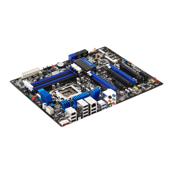
Intel Desktop Board DP67BG Product Guide Desktop Board Components Figure 1 shows the approximate location of the major components on Intel Desktop Board DP67BG. Figure 1. Intel Desktop Board DP67BG Components... -
Page 13: Intel Desktop Board Dp67Bg Components
Desktop Board Features Table 2. Intel Desktop Board DP67BG Components Label Description PCI Express 2.0 x1 connector PCI bus connector PCI Express 2.0 x16 connector (x8 electrical; x16 compatible) Front panel audio header PCI bus connector PCI Express 2.0 x1 connector PCI Express 2.0 x16 connector... -
Page 14: Processor
Intel Desktop Board DP67BG Product Guide Online Support For more information on Intel Desktop Board DP67BG consult the following online resources: • Intel Desktop Board DP67BG http://www.intel.com/products/motherboard/index.ht • Desktop Board Support http://www.intel.com/p/en_US/support?iid=hdr+supp • Available configurations for Intel http://ark.intel.com Desktop Board DP67BG •... -
Page 15: Main Memory
Main Memory NOTE ® To be fully compliant with all applicable Intel SDRAM memory specifications, the board should be populated with DIMMs that support the Serial Presence Detect (SPD) data structure. If your memory modules do not support SPD, you will see a notification to this effect on the screen at power up. -
Page 16: Intel P67 Express Chipset
® Intel P67 Express Chipset The Intel P67 Express Chipset consists of the Intel P67 Platform Controller Hub (PCH). The PCH is the centralized controller for the board’s I/O paths. Audio Subsystem The onboard audio subsystem consists of the following components: ®... -
Page 17: Lan Subsystem
Desktop Board Features LAN Subsystem The LAN subsystem includes: • Intel P67 PCH • Intel 82579V Gigabit (10/100/1000 Mb/s) Ethernet LAN controller • RJ-45 LAN connector with integrated status LEDs The subsystem features: • CSMA/CD protocol engine • LAN connect interface between PCH and the LAN controller •... -
Page 18: Usb Support
SuperSpeed, high-speed, full-speed, and low-speed capable. Serial ATA Support Intel Desktop Board DP67BG supports two onboard 6.0 Gb/s Serial ATA (SATA) channels and four onboard 3.0 Gb/s SATA channels. The board also provides one 3.0 Gb/s external SATA (eSATA) channel via a back panel connector. -
Page 19: Bios
Desktop Board Features BIOS The BIOS provides the Power-On Self-Test (POST), the BIOS Setup program, and the PCI/PCI Express and SATA auto-configuration utilities. The BIOS is stored in the Serial Peripheral Interface (SPI) Flash device. The BIOS can be updated by following the instructions in Chapter 3 starting on page 65. -
Page 20: Back To Bios Button
Figure 3. Location of the Back to BIOS Button Hardware Management The hardware management features of Intel Desktop Board DP67BG enable the board to be compatible with the Wired for Management (WfM) specification. The board has several hardware management features including the following: •... -
Page 21: Chassis Intrusion
Desktop Board Features • A thermal sensor in the processor • Thermally monitored closed-loop fan control, for all onboard fans, that can adjust fan speed Chassis Intrusion The board supports a chassis security feature that detects if the chassis cover has been removed. -
Page 22: Fan Headers
Intel Desktop Board DP67BG Product Guide Fan Headers The function/operation of the fans is as follows: • The fans are on when the computer is in the ACPI S0 state. • The fans are off when the computer is in the ACPI S3, S4, or S5 state. -
Page 23: Wake From Usb
Desktop Board Features Instantly Available PC technology enables the board to enter the ACPI S3 (Suspend-to- RAM) sleep state. While in the S3 sleep state, the computer will appear to be off. If the computer has a dual-colored power LED on the front panel, the sleep state is indicated by the LED turning amber. -
Page 24: Onboard Power And Reset Buttons
Intel Desktop Board DP67BG Product Guide Onboard Power and Reset Buttons The lighted Power button on the Desktop Board (Figure 4, B) can be used to turn the computer on or off. This button duplicates the function of the front panel power button. -
Page 25: Processor And Voltage Regulator Leds
Desktop Board Features Processor and Voltage Regulator LEDs The Desktop Board contains two red LEDs (see Figure 5) that indicate the status of the board’s voltage regulation circuitry and the processor: • The Processor LED (Figure 5, B) indicates an elevated temperature on the processor that could affect performance. -
Page 26: Diagnostic Leds
Intel Desktop Board DP67BG Product Guide Diagnostic LEDs The Desktop Board provides eight LEDs that allow you to monitor the board’s progress through the BIOS Power-on Self-Test (see Figure 6). At initial power on, all the LEDs are off. When the BIOS starts an activity such as memory initialization, the corresponding LED starts flashing. -
Page 27: Speaker
Desktop Board Features Figure 6. Location of the Diagnostic LEDs Speaker A speaker is mounted on the Desktop Board. The speaker provides audible error code (beep code) information during the Power-On Self-Test (POST). Refer to Appendix A for a description of the board’s beep codes. Battery A battery on the Desktop Board keeps the values in CMOS RAM and the clock current when the computer is turned off. - Page 28 Intel Desktop Board DP67BG Product Guide...
-
Page 29: Installing And Replacing Desktop Board Components
2 Installing and Replacing Desktop Board Components This chapter tells you how to: • Install the I/O shield • Install and remove the Desktop Board • Install and remove a processor • Install and remove memory • Install and remove a PCI Express x16 graphics card •... -
Page 30: Installation Precautions
Intel Desktop Board DP67BG Product Guide Installation Precautions When you install and test the Intel Desktop Board, observe all warnings and cautions in the installation instructions. To avoid injury, be careful of: • Sharp pins on connectors • Sharp pins on printed circuit assemblies •... -
Page 31: Installing The I/O Shield
Installing and Replacing Desktop Board Components Installing the I/O Shield The Desktop Board comes with an I/O shield. When installed in the chassis, the shield blocks radio frequency transmissions, protects internal components from dust and foreign objects, and promotes correct airflow within the chassis. Install the I/O shield before installing the Desktop Board in the chassis. -
Page 32: Installing And Removing The Desktop Board
Refer to your chassis manual for instructions on installing and removing the Desktop Board. Figure 8 shows the location of the mounting screw holes for Intel Desktop Board DP67BG. Figure 8. Intel Desktop Board DP67BG Mounting Screw Hole Locations... -
Page 33: Installing And Removing A Processor
Installing and Replacing Desktop Board Components Installing and Removing a Processor Instructions on how to install the processor on the Desktop Board are given below. Installing a Processor CAUTION Before installing or removing a processor, make sure the AC power has been removed by unplugging the power cord from the computer. -
Page 34: Lift The Load Plate
Intel Desktop Board DP67BG Product Guide 3. Rotate the socket lever to lift the load plate away from the socket (Figure 10, A). Make sure that the load plate is in the fully open position (Figure 10, B) while being careful not to damage adjacent components. -
Page 35: Remove The Processor From The Protective Cover
Installing and Replacing Desktop Board Components 4. Remove the processor from its protective cover. Hold the processor only at the edges, being careful not to touch the bottom of the processor (see Figure 11). NOTE Do not discard the processor cover. Always replace the processor cover if you remove the processor from the socket. -
Page 36: Secure The Load Plate In Place
Intel Desktop Board DP67BG Product Guide 7. Carefully lower the socket lever (Figure 13, A) while making sure that the front edge of the load plate slides under the shoulder screw cap as the lever is lowered. Latch the socket lever under the load plate tab (Figure 13, C, D). The socket cover (Figure 13, B) will pop off as shown. -
Page 37: Installing The Processor Fan Heat Sink
Installing and Replacing Desktop Board Components Installing the Processor Fan Heat Sink Intel Desktop Board DP67BG has mounting holes for a processor fan heat sink. For instructions on how to attach the processor fan heat sink to the Desktop Board, refer to the boxed processor manual or boxed thermal solution manual. -
Page 38: Installing And Removing System Memory
Intel Desktop Board DP67BG Product Guide Installing and Removing System Memory Desktop board DP67BG has four 240-pin DDR3 DIMM sockets arranged in two channels (A and B). Guidelines for Dual Channel Memory Configuration Before installing DIMMs, read and follow these guidelines for dual channel memory configuration. -
Page 39: Three Dimms
Installing and Replacing Desktop Board Components Figure 16. Example Dual Channel Memory Configuration with Four DIMMs Three DIMMs If you want to use three DIMMs in a dual-channel configuration, install a matched pair of DIMMs equal in speed and size in DIMM 1 and DIMM 3 of channel A. Then install another DIMM equal to the speed and total size of the DIMMs installed in channel A in either DIMM 2 or DIMM 4 of channel B (Figure 17). -
Page 40: Installing Dimms
Intel Desktop Board DP67BG Product Guide Installing DIMMs To make sure you have the correct DIMM, place it on the illustration of the DDR3 DIMM in Figure 18. All the notches should match with the DDR3 DIMM. Figure 18. Use DDR3 DIMMs... -
Page 41: Installing A Dimm
Installing and Replacing Desktop Board Components NOTE For best memory performance, install memory in the blue DIMM sockets first. To install a DIMM, follow these steps: 1. Observe the precautions in "Before You Begin" on page 29. 2. Turn off all peripheral devices connected to the computer. Turn off the computer and disconnect the AC power cord. -
Page 42: Removing Dimms
Intel Desktop Board DP67BG Product Guide Removing DIMMs To remove a DIMM, follow these steps: 1. Observe the precautions in "Before You Begin" on page 29. 2. Turn off all peripheral devices connected to the computer. Turn off the computer. -
Page 43: Installing A Pci Express X16 Graphics Card
Installing and Replacing Desktop Board Components Follow these instructions to install a PCI Express x16 graphics card: 1. Observe the precautions in "Before You Begin" on page 29. 2. Place the card in the PCI Express x16 connector (Figure 20, A) and press down on the card until it is completely seated in the connector and the card retention notch on the card snaps into place around the retention mechanism pin on the connector. -
Page 44: Removing A Pci Express X16 Graphics Card
Intel Desktop Board DP67BG Product Guide Removing a PCI Express x16 Graphics Card Follow these instructions to remove a PCI Express x16 graphics card from a connector: 1. Observe the precautions in "Before You Begin" on page 29. 2. Remove the screw (Figure 21, A) that secures the card’s metal bracket to the chassis back panel. -
Page 45: Installing Linked Pci Express Graphics Cards
Installing and Replacing Desktop Board Components To install two linked PCI Express graphics cards: 1. Observe the precautions in "Before You Begin" on page 29. 2. Install the first card in the PCI Express x16 connector as described in “Installing a PCI Express x16 Graphics Card”... -
Page 46: Connecting The Serial Ata (Sata) Cables
Intel Desktop Board DP67BG Product Guide Connecting the Serial ATA (SATA) Cables SATA cables support the Serial ATA protocol. Each cable can be used to connect one internal SATA drive to the Desktop Board. For correct cable function: 1. Observe the precautions in “Before You Begin” on page 29. -
Page 47: Connecting To The Internal Headers
Connecting to the Internal Headers Before connecting cables to any of the internal headers, observe the precautions in “Before You Begin” on page 29. Figure 24 shows the location of the internal headers and connectors on Intel Desktop Board DP67BG. Figure 24. Internal Headers... -
Page 48: S/Pdif Header
Key (no pin) Ground Front Panel Intel HD Audio Header Figure 24, C shows the location of the front panel Intel HD Audio header. Table 8 shows the pin assignments and signal names for the front panel Intel HD Audio header. -
Page 49: Alternate Front Panel Power Led Header
Installing and Replacing Desktop Board Components Alternate Front Panel Power LED Header Figure 24, D shows the location of the alternate front panel power LED header. Pins 1 and 3 of this header duplicate the signals on pins 2 and 4 of the front panel header. If your chassis has a three-pin power LED cable, connect it to this header. -
Page 50: Back Panel Cir Header Emitter (Output) Header Signal Names
Intel Desktop Board DP67BG Product Guide Table 11. Back Panel CIR Header Emitter (Output) Header Signal Names Signal Name Signal Name Emitter Out 1 Emitter Out 2 Ground Key (no pin) Jack Detect 1 Jack Detect 2 USB 2.0 Headers Figure 24, G shows the location of the USB 2.0 headers. -
Page 51: Front Panel Header
Installing and Replacing Desktop Board Components Front Panel Header Figure 24, H shows the location of the front panel header. Table 13 shows the pin assignments and signal names for the front panel header. Table 13. Front Panel Header Signal Names Description In/Out Pin Description... -
Page 52: Connecting To The Audio System
Intel Desktop Board DP67BG Product Guide Connecting to the Audio System ® After installing the Realtek audio driver from the Intel Express Installer DVD-ROM, the multi-channel audio feature can be enabled. Figure 25 shows the back panel audio connectors. The default connector assignments are shown in the table. -
Page 53: Connecting Chassis Fan And Power Supply Cables
Installing and Replacing Desktop Board Components Connecting Chassis Fan and Power Supply Cables Connecting Chassis Fan Cables Connect chassis fan cables to the chassis fan headers on the Desktop Board. Figure 26 shows the location of the chassis fan headers. Figure 26. -
Page 54: Connecting Power Supply Cables
Intel Desktop Board DP67BG Product Guide Connecting Power Supply Cables Figure 27 shows the location of the power connectors. CAUTION Failure to use an appropriate power supply and/or not connecting the 12 V (Figure 27, A) power connector to the Desktop Board may result in damage to the board or the system may not function properly. -
Page 55: Setting The Bios Configuration Jumper
Installing and Replacing Desktop Board Components 1. Observe the precautions in "Before You Begin" on page 29. 2. Connect the 12 V processor core voltage power supply cable to the 2 x 4 pin connector (Figure 27, A). 3. Connect the main power supply cable to the 2 x 12 pin connector (Figure 27, C). Setting the BIOS Configuration Jumper NOTE Always turn off the power and unplug the power cord from the computer before... -
Page 56: Clearing Passwords
Intel Desktop Board DP67BG Product Guide Table 15. Jumper Settings for the BIOS Setup Program Modes Jumper Setting Mode Description Normal (default) (1-2) The BIOS uses the current configuration and passwords for booting. Configure (2-3) After the Power-On Self-Test (POST) runs, the BIOS displays the Maintenance Menu. -
Page 57: Replacing The Battery
Installing and Replacing Desktop Board Components 10. Turn off the computer. Disconnect the computer’s power cord from the AC power source. 11. Remove the computer cover. 12. To restore normal operation, place the jumper on pins 1-2 as shown below. 13. - Page 58 Intel Desktop Board DP67BG Product Guide VIKTIGT! Risk för explosion om batteriet ersätts med felaktig batterityp. Batterier ska kasseras enligt de lokala miljövårdsbestämmelserna. VARO Räjähdysvaara, jos pariston tyyppi on väärä. Paristot on kierrätettävä, jos se on mahdollista. Käytetyt paristot on hävitettävä paikallisten ympäristömääräysten mukaisesti.
- Page 59 Installing and Replacing Desktop Board Components UPOZORNÌNÍ V případě výměny baterie za nesprávný druh může dojít k výbuchu. Je-li to možné, baterie by měly být recyklovány. Baterie je třeba zlikvidovat v souladu s místními předpisy o životním prostředí. Προσοχή Υπάρχει κίνδυνος για έκρηξη σε περίπτωση που η μπαταρία αντικατασταθεί από μία λανθασμένου...
- Page 60 Intel Desktop Board DP67BG Product Guide ВНИМАНИЕ При использовании батареи несоответствующего типа существует риск ее взрыва. Батареи должны быть утилизированы по возможности. Утилизация батарей должна проводится по правилам, соответствующим местным требованиям. UPOZORNENIE Ak batériu vymeníte za nesprávny typ, hrozí nebezpečenstvo jej výbuchu. Batérie by sa mali podľa možnosti vždy recyklovať.
- Page 61 Installing and Replacing Desktop Board Components...
- Page 62 Intel Desktop Board DP67BG Product Guide To replace the battery, follow these steps: 1. Observe the precautions in "Before You Begin" (see page 29). 2. Turn off all peripheral devices connected to the computer. Disconnect the computer’s power cord from the AC power source (wall outlet or power adapter).
-
Page 63: Installing The Wifi/Bluetooth* Module In A Desktop Chassis
The WiFi/Bluetooth*module is supplemental hardware that is included with certain Desktop Boards. Additional WiFi/Bluetooth modules can be ordered online from http://click.intel.com/Desktop_system_parts-0-C97.aspx Installing the WiFi/Bluetooth module that is shipped with Intel Desktop Board DP67BG in your desktop system allows you to connect to wireless networks and Bluetooth peripherals. -
Page 64: Installing The Wifi/Bluetooth Module
Intel Desktop Board DP67BG Product Guide Figure 30. Installing the WiFi/Bluetooth Module... -
Page 65: Updating The Bios
Power-On Self-Test (POST) memory test begins and before the operating system boot begins. This chapter tells you how to update the BIOS by either using the Intel Express BIOS Update utility or the Iflash Memory Update utility, and how to recover the BIOS if an update fails. -
Page 66: Updating The Bios Using The F7 Function Key
Memory Update Utility or the ISO Image BIOS Update File ® You can use the information in this section to update the BIOS using either the Intel Flash Memory Update Utility or the ISO Image BIOS update file. Obtaining the BIOS Update File You can update to a new version of the BIOS by using the ISO Image BIOS update file (recommended), or Intel Flash Memory BIOS update file. -
Page 67: Updating The Bios With The Intel Flash Memory Update Utility
Updating the BIOS with the Intel Flash Memory Update Utility With the Intel Flash Memory Update Utility you can update the system BIOS from a bootable CD-ROM, bootable USB flash drive, or other bootable USB media. The utility available on the Intel World Wide Web site provides a simple method for creating a bootable CD-ROM that will automatically update your BIOS. -
Page 68: Recovering The Bios
CD-R with the .BIO file in the root directory will be required. You can obtain the Recovery BIOS Update file through your computer supplier or by navigating to the Intel Desktop Board DP67BG page on the Intel World Wide Web site Download Center at http://downloadcenter.intel.com. -
Page 69: Configuring For Raid Using Intel Rapid Storage Technology
4. Then save your settings by pressing <F10>. Creating Your RAID Set 1. Upon re-boot, you will see the following Intel Rapid Storage Manager option ROM status message on the screen: Press <Ctrl-I> to enter the RAID Configuration Utility. Press <Ctrl-I> and enter the RAID Configuration Utility. -
Page 70: Loading The Intel Rapid Storage Technology Raid Drivers And Software (Required For Microsoft Windows Xp Installation)
SATA RAID Controller driver. 3. Finish the Windows installation and install all necessary drivers. 4. Install the Intel Rapid Storage Console software via the Intel Express Installer CD included with your Desktop Board or after downloading it from the Internet at http://support.intel.com/support/motherboards/desktop/. -
Page 71: A Error Messages And Indicators
A Error Messages and Indicators Intel Desktop Board DP67BG reports POST errors in three ways: • By sounding a beep code and blinking the front panel power LED • By displaying an error message on the monitor • By displaying diagnostic progress codes (POST codes) BIOS Error Codes Whenever a recoverable error occurs during POST, the BIOS causes the board’s... -
Page 72: Bios Error Messages
Intel Desktop Board DP67BG Product Guide BIOS Error Messages When a recoverable error occurs during the POST, the BIOS displays an error message describing the problem. Table 18 gives an explanation of the BIOS error messages. Table 18. BIOS Error Messages... -
Page 73: Port 80H Post Codes
Error Messages and Indicators Port 80h POST Codes During the POST, the BIOS generates diagnostic progress codes (POST codes) to I/O port 80h. If the POST fails, execution stops and the last POST code generated is left at port 80h and displayed on the Desktop Board’s seven-segment LED display shown in Figure 31. - Page 74 Intel Desktop Board DP67BG Product Guide POST Code Description PEI Phase Before MRC Set bootmode, GPIO init Early chipset register programming Basic PCH init, discrete device init LAN init Exit early platform init driver SMBUS driver init 17, 18 Entry/Exit to SMBUS execute read/write...
- Page 75 Error Messages and Indicators POST Code Description Keyboard/Mouse (PS/2 or USB) 90-95 Keyboard initialization 98-9B Mouse initialization Fixed Media B0-BF Detecting and initializing fixed media Runtime Phase/EFI Operating System Boot EFI boot service ExitBootServices EFI runtime service SetVirtualAddressMap...
- Page 76 Intel Desktop Board DP67BG Product Guide...
-
Page 77: B Regulatory Compliance
Product Ecology statements • Electromagnetic Compatibility (EMC) regulations • Product certifications Safety Standards Intel Desktop Board DP67BG complies with the safety standards stated in Table 20 when correctly installed in a compatible host system. Table 20. Safety Standards Regulation Title CSA/UL 60950-1 Information Technology Equipment –... -
Page 78: European Union Declaration Of Conformity Statement
Intel Desktop Board DP67BG Product Guide European Union Declaration of Conformity Statement We, Intel Corporation, declare under our sole responsibility that the product Intel ® Desktop Board DP67BG is in conformity with all applicable essential requirements necessary for CE marking, following the provisions of the European Council Directives 2004/108/EC (EMC Directive), 2006/95/EC (Low Voltage Directive), and 2002/95/EC (ROHS Directive). -
Page 79: Product Ecology Statements
The following information is provided to address worldwide product ecology concerns and regulations. Recycling Considerations As part of its commitment to environmental responsibility, Intel has implemented the ® Intel Product Recycling Program to allow retail consumers of Intel’s branded products to return used products to selected locations for proper recycling. - Page 80 Français Dans le cadre de son engagement pour la protection de l'environnement, Intel a mis en œuvre le programme Intel Product Recycling Program (Programme de recyclage des produits Intel) pour permettre aux consommateurs de produits Intel de recycler les produits usés en les retournant à...
- Page 81 Regulatory Compliance Portuguese Como parte deste compromisso com o respeito ao ambiente, a Intel implementou o Programa de Reciclagem de Produtos para que os consumidores finais possam enviar produtos Intel usados para locais selecionados, onde esses produtos são reciclados de maneira adequada.
-
Page 82: China Rohs
The China Ministry of Information Industry (MII) stipulates that a material Self Declaration Table (SDT) must be included in a product’s user documentation. The SDT for Intel Desktop Board DP67BG is shown in Figure 32. Figure 32. Intel Desktop Board DP67BG China RoHS Material... -
Page 83: Emc Regulations
Regulatory Compliance EMC Regulations Intel Desktop Board DP67BG complies with the EMC regulations stated in Table 21 when correctly installed in a compatible host system. Table 21. EMC Regulations Regulation Title FCC 47 CFR Part 15, Title 47 of the Code of Federal Regulations, Part 15, Subpart B, Subpart B Radio Frequency Devices. -
Page 84: Canadian Department Of Communications Compliance Statement
• Consult the dealer or an experienced radio/TV technician for help. Any changes or modifications to the equipment not expressly approved by Intel Corporation could void the user’s authority to operate the equipment. Tested to comply with FCC standards for home or office use. -
Page 85: Korea Class B Statement
Regulatory Compliance Korea Class B Statement Korea Class B Statement translation: This equipment is for home use, and has acquired electromagnetic conformity registration, so it can be used not only in residential areas, but also other areas. Ensure Electromagnetic Compatibility (EMC) Compliance Before computer integration, make sure that the power supply and other modules or peripherals, as applicable, have passed Class B EMC testing and are marked... -
Page 86: Product Certifications
Intel Desktop Board DP67BG Product Guide Product Certifications Board-Level Certifications Intel Desktop Board DP67BG has the regulatory compliance marks shown in Table 22. Table 22. Regulatory Compliance Marks Description Mark UL joint US/Canada Recognized Component mark. Includes adjacent UL file number for Intel Desktop Boards: E210882. -
Page 87: Chassis- And Component-Level Certifications
Regulatory Compliance Chassis- and Component-Level Certifications Ensure that the chassis and certain components; such as the power supply, peripheral drives, wiring, and cables; are components certified for the country or market where used. Agency certification marks on the product are proof of certification. Typical product certifications include: In Europe The CE mark indicates compliance with all applicable European requirements. -
Page 88: Energy Star*, E-Standby, And Erp Compliance
Compliance The US Department of Energy and the US Environmental Protection Agency have continually revised the ENERGY STAR requirements. Intel has worked directly with these two governmental agencies in the definition of the new requirements. Intel Desktop Board DP67BG meets the following program requirements in an...