Table of Contents
Advertisement
Service
Manual
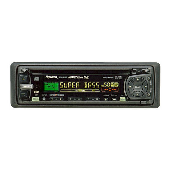
MULTI-CD CONTROL HIGH POWER CD PLAYER WITH FM/AM TUNER
DEH-P300
DEH-P3000
DEH-P200
- See the separate manual CX-916(CRT2300) for the CD mechanism description, disassembly and circuit
description.
- The CD mechanism employed in this model is one of S8 series.
CONTENTS
1. SAFETY INFORMATION ............................................2
2. EXPLODED VIEWS AND PARTS LIST .......................2
3. SCHEMATIC DIAGRAM ...........................................12
4. PCB CONNECTION DIAGRAM ................................34
5. ELECTRICAL PARTS LIST ........................................44
6. ADJUSTMENT..........................................................52
PIONEER ELECTRONIC CORPORATION
PIONEER ELECTRONICS SERVICE INC.
PIONEER ELECTRONIC [EUROPE] N.V.
PIONEER ELECTRONICS ASIACENTRE PTE.LTD. 253 Alexandra Road, #04-01, Singapore 159936
C PIONEER ELECTRONIC CORPORATION 1998
DEH-P300/X1N/UC
1
X
4-1, Meguro 1-Chome, Meguro-ku, Tokyo 153-8654, Japan
P.O.Box 1760, Long Beach, CA 90801-1760 U.S.A.
Haven 1087 Keetberglaan 1, 9120 Melsele, Belgium
1
X
N/UC
N/UC
7. GENERAL INFORMATION .......................................56
7.1 PARTS .................................................................56
7.1.1 IC................................................................56
7.1.2 DISPLAY ....................................................63
7.2 DIAGNOSIS ........................................................64
7.2.1 DISASSEMBLY .........................................64
7.2.2 TEST MODE ..............................................65
7.3 BLOCK DIAGRAM ..............................................69
8. OPERATIONS AND SPECIFICATIONS.....................71
K-ZZD. DEC. 1998 Printed in Japan
ORDER NO.
CRT2310
1
X
N/UC
Advertisement
Table of Contents

Related Manuals for Pioneer DEH-P300


Summary of Contents for Pioneer DEH-P300
-
Page 1: Table Of Contents
PIONEER ELECTRONICS SERVICE INC. P.O.Box 1760, Long Beach, CA 90801-1760 U.S.A. PIONEER ELECTRONIC [EUROPE] N.V. Haven 1087 Keetberglaan 1, 9120 Melsele, Belgium PIONEER ELECTRONICS ASIACENTRE PTE.LTD. 253 Alexandra Road, #04-01, Singapore 159936 C PIONEER ELECTRONIC CORPORATION 1998 K-ZZD. DEC. 1998 Printed in Japan... -
Page 2: Safety Information
DEH-P300,P3000,P200 - CD Player Service Precautions 2. During disassembly, be sure to turn the power off 1. For pickup unit(CXX1285) handling, please refer since an internal IC might be destroyed when a con- to"Disassembly"(CX-916 Service Manual CRT2300). nector is plugged or unplugged. - Page 3 13 ••••• 14 Carton See Contrast table(2) 15 Contain Box See Contrast table(2) (2) CONTRAST TABLE DEH-P300/X1N/UC, DEH-P3000/X1N/UC and DEH-P200/X1N/UC are constructed the same except for the following: Part No. Mark No. Symbol and Description DEH-P300/X1N/UC DEH-P3000/X1N/UC DEH-P200/X1N/UC 14 Carton...
- Page 4 DEH-P300,P3000,P200 2.2 EXTERIOR - DEH-P300/X1N/UC...
- Page 5 DEH-P300,P3000,P200 - EXTERIOR SECTION PARTS LIST Mark No. Description Part No. Mark No. Description Part No. 1 Screw BMZ26P120FMC 51 Bracket CNC6791 2 Screw BSZ26P060FMC 52 Holder CNC8042 3 Screw BSZ30P060FMC 53 Cover CNM6276 4 Screw BSZ30P120FMC 54 Panel CNS5189...
- Page 6 DEH-P300,P3000,P200 - DEH-P3000/X1N/UC...
- Page 7 DEH-P300,P3000,P200 - EXTERIOR SECTION PARTS LIST Mark No. Description Part No. Mark No. Description Part No. 1 Screw BMZ26P120FMC 51 Bracket CNC6791 2 Screw BSZ26P060FMC 52 Holder CNC8042 3 Screw BSZ30P060FMC 53 Cover CNM6276 4 Screw BSZ30P120FMC 54 Panel CNS5189...
- Page 8 DEH-P300,P3000,P200 - DEH-P200/X1N/UC...
- Page 9 DEH-P300,P3000,P200 - EXTERIOR SECTION PARTS LIST Mark No. Description Part No. Mark No. Description Part No. 1 Screw BMZ26P120FMC 51 Bracket CNC6791 2 Screw BSZ26P060FMC 52 Holder CNC8042 3 Screw BSZ30P060FMC 53 Cover CNM6276 4 Screw BSZ30P120FMC 54 Panel CNS5355...
- Page 10 DEH-P300,P3000,P200 2.3 CD MECHANISM MODULE...
- Page 11 DEH-P300,P3000,P200 - CD MECHANISM MODULE SECTION PARTS LIST Mark No. Description Part No. Mark No. Description Part No. 1 Control Unit CWX2344 46 Sheet CNM6215 2 Connector(CN802) CKS2192 47 Ball CNR1189 3 Connector(CN801) CKS2193 48 Belt CNT1086 4 Connector(CN701) CKS2773...
-
Page 12: Schematic Diagram
DEH-P300,P3000,P200 3. SCHEMATIC DIAGRAM 3.1 OVERALL CONNECTION DIAGRAM(GUIDE PAGE)(DEH-P300/X1N/UC) Note: When ordering service parts, be sure to refer to “EXPLODED VIEWS AND PARTS LIST” or “ELECTRICAL PARTS LIST”. Large size SCH diagram IP BUS IN 4.3V 4.3V 4.3V 4.3V 4.3V... - Page 13 DEH-P300,P3000,P200 4.3V 4.3V 4.3V 4.2V 1.8V 4.2V 4.2V 4.3V 4.3V URCE SELECTOR, ECTRONIC VOLUME RESET CEK1136 CEK1014...
- Page 14 DEH-P300,P3000,P200...
- Page 15 DEH-P300,P3000,P200...
- Page 16 DEH-P300,P3000,P200...
- Page 17 DEH-P300,P3000,P200...
- Page 18 DEH-P300,P3000,P200 3.2 OVERALL CONNECTION DIAGRAM(GUIDE PAGE)(DEH-P3000/X1N/UC, DEH-P200/X1N/UC) IP BUS IN 4.3V 4.3V 4.3V 4.3V 4.3V IP BUS 4.3V DRIVER 4.3V 4.3V 4.3V 4.3V ANTENNA CABLE VD REGULATOR...
- Page 19 DEH-P300,P3000,P200 4.3V 4.3V 4.3V 4.3V OURCE SELECTOR, LECTRONIC VOLUME RESET CEK1136 CEK1014...
- Page 20 DEH-P300,P3000,P200...
- Page 21 DEH-P300,P3000,P200...
- Page 22 DEH-P300,P3000,P200...
- Page 23 DEH-P300,P3000,P200 100K...
- Page 24 DEH-P300,P3000,P200 3.3 FM/AM TUNER UNIT Voltage of IC Terminals Mark Band Input Level None – – 0dBf 65dBf F125 125dBf 74dB A125 125dB...
- Page 25 DEH-P300,P3000,P200...
- Page 26 DEH-P300,P3000,P200 3.4 KEYBOARD UNIT KEYBOARD UNIT PROGRAM CLOCK...
- Page 27 DEH-P300,P3000,P200 CAW1497 DEH-P300/X1N/UC, DEH-P3000/X1N/UC CAW1500 DEH-P200/X1N/UC PD6294A...
- Page 28 DEH-P300,P3000,P200 3.5 CD MECHANISM MODULE CONTROL UNIT PICKUP UNIT(SERVICE) PHOTO UNIT...
- Page 29 DEH-P300,P3000,P200 SWITCHES: CONTROL UNIT S801 : HOME SWITCH..ON-OFF S802 : CLAMP SWITCH..ON-OFF The underlined indicates the switch position.
- Page 30 DEH-P300,P3000,P200 Note:1. The encircled numbers denote measuring pointes in the circuit diagram. 2. Reference voltage REFO:2.5V - Waveforms 1 RFI 1 CH1: RFI 1 CH1: RFI 0.5V/div. 0.5µs/div. 1V/div. 1V/div. 0.5ms/div. 0.5ms/div. 2 CH2: MIRR 2 CH2: MIRR Normal mode: play 5V/div.
- Page 31 DEH-P300,P3000,P200 8 CH1: TE 8 CH1: TE 0 MD 0.2V/div. 0.5V/div. 0.5V/div. 0.1s/div. 20ms/div. 5ms/div. 9 CH2: TD ! CH2: SD 0.2V/div. 0.5V/div. Normal mode: play TEST mode: 100 Tracks jump(FWD) Normal mode: Play (12cm) REFO REFO REFO REFO REFO...
- Page 32 DEH-P300,P3000,P200 ( CH1: R OUT 6 CH1: FE 8 CH1: TE 1V/div. 0.2V/div. 0.2V/div. 0.2ms/div. 1ms/div. 1ms/div. ) CH2: L OUT 9 CH2: TD 3 CH2: FD 1V/div. 0.5V/div. 0.5V/div. Normal mode: Play (1kHz 0dB) Normal mode: During AGC Normal mode: During AGC...
- Page 33 DEH-P300,P3000,P200...
-
Page 34: Pcb Connection Diagram
DEH-P300,P3000,P200 4. PCB CONNECTION DIAGRAM 4.1 TUNER AMP UNIT NOTE FOR PCB DIAGRAMS TUNER AMP UNIT 1. The parts mounted on this PCB include all necessary parts for several destination. For further information for respective destinations, be sure to check with the schematic dia- gram. - Page 35 DEH-P300,P3000,P200 SIDE A CORD ASSY IP BUS IN SUB WOOFER/ REAR PREOUT L ch R ch CN1801...
- Page 36 DEH-P300,P3000,P200 TUNER AMP UNIT...
- Page 37 DEH-P300,P3000,P200 SIDE B...
- Page 38 DEH-P300,P3000,P200 4.2 FM/AM TUNER UNIT SIDE A...
- Page 39 DEH-P300,P3000,P200 SIDE B...
- Page 40 DEH-P300,P3000,P200 4.3 KEYBOARD UNIT SIDE A...
- Page 41 DEH-P300,P3000,P200 SIDE B...
- Page 42 DEH-P300,P3000,P200 4.4 CD MECHANISM MODULE SIDE A...
- Page 43 DEH-P300,P3000,P200 SIDE B...
-
Page 44: Electrical Parts List
CKS.., CCS.., CSZS..=====Circuit Symbol and No.===Part Name Part No. =====Circuit Symbol and No.===Part Name Part No. --------- ------------------------------------------ ------------------------- ------ ------------------------------------------ ------------------------- Unit Number : CWM6082(DEH-P300/X1N/UC) Diode HZS9L(B1) Unit Name : Tuner Amp Unit Inductor LAU3R3J Ferri-Inductor LAU4R7K MISCELLANEOUS... - Page 45 DEH-P300,P3000,P200 =====Circuit Symbol and No.===Part Name Part No. =====Circuit Symbol and No.===Part Name Part No. ------ ------------------------------------------ ------------------------- ------ ------------------------------------------ ------------------------- RS1/10S562J RD1/4PU302J RS1/10S223J RS1/10S1R0J RS1/10S513J RS1/10S681J RS1/10S513J RD1/4PU102J RS1/10S473J RS1/10S102J RS1/10S473J RD1/4PU102J RS1/10S330J RS1/10S223J RS1/10S0R0J RS1/10S223J RS1/10S0R0J RS1/10S103J RD1/4PU222J...
- Page 46 DEH-P300,P3000,P200 =====Circuit Symbol and No.===Part Name Part No. =====Circuit Symbol and No.===Part Name Part No. ------ ------------------------------------------ ------------------------- ------ ------------------------------------------ ------------------------- CKSQYB103K50 Transistor DTC124ES CKSQYB223K50 Transistor 2SA933S CKSQYB223K50 Transistor DTC124ES CEJA220M10 Transistor 2SC1740S CKSQYB102K50 Transistor 2SB1243 CEAL101M10 Transistor DTC143EU CKSQYB473K25...
- Page 47 DEH-P300,P3000,P200 =====Circuit Symbol and No.===Part Name Part No. =====Circuit Symbol and No.===Part Name Part No. ------ ------------------------------------------ ------------------------- ------ ------------------------------------------ ------------------------- RS1/10S821J RD1/4PU222J RS1/10S223J RD1/4PU222J RS1/10S223J RD1/4PU222J RS1/10S223J RS1/10S473J RS1/10S223J RD1/4PU472J RS1/10S0R0J RS1/8S472J RS1/8S473J RD1/4PU302J RD1/4PU221J RS1/10S1R0J RD1/4PU221J RS1/10S681J RS1/10S0R0J...
- Page 48 DEH-P300,P3000,P200 =====Circuit Symbol and No.===Part Name Part No. =====Circuit Symbol and No.===Part Name Part No. ------ ------------------------------------------ ------------------------- ------ ------------------------------------------ ------------------------- CKSQYB223K50 Inductor LCTB330K1608 CEJA220M10 Inductor CTF1287 CKSQYB102K50 Inductor LCTA121J3225 CEAL101M10 Coil CTC1154 CKSQYB473K25 Inductor LCTA3R3J3225 CCSQCH101J50 Inductor LCTBR47K1608 CKSQYB102K50...
- Page 49 CKSRYB103K50 CKSYB475K10 CKSRYB473K16 CKSRYB223K25 CCSRCK2R0C50 CKSQYB225K10 CKSRYB103K50 CCSRCH270J50 CKSRYB104K16 CCSRCH270J50 CKSRYB104K16 CKSYB105K16 CKSQYB224K16 CKSRYB103K50 CEALNP100M10 CCSRCH151J50 Unit Number : CWM6096(DEH-P300/X1N/UC, CKSRYB473K16 DEH-P3000/X1N/UC) CKSRYB682K25 Unit Name : Keyboard Unit CEALR68M50 MISCELLANEOUS CKSRYB103K50 CKSQYB474K16 IC 1801 PD6294A CKSQYB474K16 1801 Diode Network DA204U...
- Page 50 DEH-P300,P3000,P200 =====Circuit Symbol and No.===Part Name Part No. =====Circuit Symbol and No.===Part Name Part No. ------ ------------------------------------------ ------------------------- ------ ------------------------------------------ ------------------------- 1805 Lamp 14V 40mA CEL1549 Unit Number : CWX2344 LCD1801 CAW1497 Unit Name : Control Unit RESISTORS MISCELLANEOUS 1801...
- Page 51 DEH-P300,P3000,P200 =====Circuit Symbol and No.===Part Name Part No. ------ ------------------------------------------ ------------------------- CKSQYB104K16 CKSQYB104K16 CEV470M16 CKSRYB471K50 CEV4R7M35 CEV4R7M35 CCSQSL152J50 CCSQSL152J50 CEV220M6R3 CEV101M6R3 22µF/6.3V CCH1300 CKSQYB334K16 Unit Number : Unit Name : Photo Unit Photo-transistor CPT230SX-TU Photo-transistor CPT230SX-TU Miscellaneous Parts List Pickup Unit(Service)(P8)
-
Page 52: Adjustment
DEH-P300,P3000,P200 6. ADJUSTMENT 6.1 CD ADJUSTMENT 1) Precautions 2) Test Mode • This unit uses a single power supply (+5V) for the reg- This mode is used for adjusting the CD mechanism ulator. The signal reference potential, therefore, is module of the device. - Page 53 DEH-P300,P3000,P200 - Flow Chart Test Mode In Reset Sourse CD SOURCE New test mode BAND Power ON (Adjustment for T.Offset) Power ON RF AMP Gain Select (Not adjustment for T.Offset) 00 00 00 Display 99 99 99 GG GG GG...
-
Page 54: Checking The Grating After Changing The Pickup Unit
DEH-P300,P3000,P200 6.2 CHECKING THE GRATING AFTER CHANGING THE PICKUP UNIT • Note : The grating angle of the PU unit cannot be adjusted after the PU unit is changed. The PU unit in the CD mecha- nism module is adjusted on the production line to match the CD mechanism module and is thus the best adjusted PU unit for the CD mechanism module. - Page 55 DEH-P300,P3000,P200 Xch 20mV/div, AC Grating waveform Ych 20mV/div, AC...
-
Page 56: General Information
DEH-P300,P3000,P200 7. GENERAL INFORMATION 7.1 PARTS 7.1.1 IC - Pin Functions (PD4989A) Pin No. Pin Name Function and Operation DRSYS Door system select output DRSENS Door open / close sense input SYSPW System power supply control output DRELAY External relay output... - Page 57 DEH-P300,P3000,P200 Pin No. Pin Name Function and Operation clamp CD disc clamp sense input xsck CD LSI clock output CD LSI data input CD LSI data output CD LSI command/data control output xrst CD LSI reset output xstb CD LSI strobe output...
- Page 58 DEH-P300,P3000,P200 - Pin Functions (PD6294A) Pin No. Pin Name Function and Operation Crystal oscillator connection pin Crystal oscillator connection pin Not used MOD1,0 Connect to GND Not used KYDT Key data output DPDT Display data input REMIN Remote control pulse input...
- Page 59 DEH-P300,P3000,P200 PML003AM Rear- Loud- Front- IN1_R IN2_R IN3_R IN4+_R IN4-_R AGND out_R SVin_R out_R out_R FIE_R DATA Isolator circuit Anti radiation Fader Secondary Anti Alias filter volume volume filter Loudness volume Primary Treble Zero cross volume Auto-Zero detect circuit Bass...
- Page 60 DEH-P300,P3000,P200 - Pin Functions (UPD63710GC) Pin No. Pin Name Function and Operation Logic circuit GND HOLD Defect detection output MIRR MIRR output RFOK signal output Reset signal input Command/parameter identification signal input Data strobe signal input Clock signal input for serial data input/output...
- Page 61 DEH-P300,P3000,P200 Pin No. Pin Name Function and Operation ATEST Test pin RFMODE Use/not use select for internal RF amplifier A.GND Analog circuit GND Focus drive output Tracking drive output Sled drive output Spindle drive output DACO DAC output for adjustment...
- Page 62 DEH-P300,P3000,P200 - Pin Functions (BA5985FM) Pin No. Pin Name Function and Operation Loading driver FWD input OPIN1( ) CH1 pre-amplifier input OPIN1( ) CH1 pre-amplifier inverted input OPOUT1 CH1 pre-amplifier output OPIN2( ) CH2 pre-amplifier input OPIN2( ) CH2 pre-amplifier inverted input...
-
Page 63: Display
DEH-P300,P3000,P200 7.1.2 DISPLAY - CAW1497, CAW1500... -
Page 64: Diagnosis
DEH-P300,P3000,P200 7.2 DIAGNOSIS 7.2.1 DISASSEMBLY Removing the Case Unit(not shown) 1. Remove the Case Unit. Removing the Panel Assy(Fig.1) Disengage the stoppers at two locations. Remove the Panel Assy. Removing the CD Mechanism Module (not shown) 1. Remove the four screws. -
Page 65: Test Mode
DEH-P300,P3000,P200 7.2.2 TEST MODE - Error Messages If a CD is not operative or stopped during operation due to an error, the error mode is turned on and cause(s) of the error is indicated with a corresponding number. This arrangement is intended at reducing nonsense calls from the users and also for facilitating trouble analysis and repair work in servicing. - Page 66 DEH-P300,P3000,P200 - New Test Mode S-CD plays the same way as before. If an error such as off focus, spindle unlocking, unreadable sub-code, or sound skipping occurs after setup, its cause and time occurred (in absolute time) are displayed. During setup, operational status of the control software (internal RAM: CPOINT) is displayed.
- Page 67 DEH-P300,P3000,P200 (4) Display of Operational Status (CPOINT) during Setup Status No. Contents Protective action CD 5V ON process in progress. None Servo LSI initialization (1/3) in progress. None Servo LSI CRAM initialization in progress. None Servo LSI initialization (2/3) in progress.
- Page 68 DEH-P300,P3000,P200 (5) Display Examples 1) During Setup (When status no. = 11) TRK No. MIN. SEC. 11" 2) During Operation (TOC read, TRK search, Play, FF and REV) The same as in the normal mode. 3) When a Protection Error Occurred Switch to the following displays (A) and (B) using the [BAND] switch: (A) Error occurrence timing display in absolute time.
-
Page 69: Block Diagram
DEH-P300,P3000,P200 7.3 BLOCK DIAGRAM - DEH-P300/X1N/UC TUNER AMP UNIT FM/AM TUNER UNIT CONTROL UNIT PICKUP UNIT(SERVICE) PHOTO UNIT KEYBOARD UNIT... - Page 70 DEH-P300,P3000,P200 - DEH-P3000/X1N/UC, DEH-P200/X1N/UC TUNER AMP UNIT FM/AM TUNER UNIT CONTROL UNIT PICKUP UNIT(SERVICE) PHOTO UNIT KEYBOARD UNIT...
-
Page 71: Operations And Specifications
DEH-P300,P3000,P200 8. OPERATIONS AND SPECIFICATIONS 8.1 OPERATIONS Key Finder Head Unit 5/∞/2/3 buttons Disc loading slot EJECT button FUNCTION button +/– button AUDIO button DETACH button EQ button Buttons 1 – 6 BAND button DISPLAY button CLOCK button SOURCE button... - Page 72 DEH-P300,P3000,P200 To Listen to Music The following explains the initial operations required before you can listen to music. Note: • Loading a disc in this product. 1. Select the desired source (e.g. tuner). Each press changes the Source ... 7 Head Unit...
- Page 73 DEH-P300,P3000,P200 Basic Operation Basic Operation of Tuner Manual and Seek Tuning • You can select the tuning method by changing the length of time you press the 2/3 button. Manual Tuning (step by step) 0.5 seconds or less Seek Tuning 0.5 seconds or more...
- Page 74 DEH-P300,P3000,P200 Basic Operation Basic Operation of Multi-CD Player This product can control one or more multi-CD players. (There are some types of multi- CD players such as “CDX-P630S” which you cannot connect more than one.) Track Search and Fast Forward/Reverse •...
- Page 75 DEH-P300,P3000,P200 Disc Number Search (for 6-Disc, 12-Disc types) • You can select discs directly with the 1 to 6 buttons. Just press the number corresponding to the disc you want to listen to. Note: • When a 12-Disc Multi-CD Player is connected and you want to select disc 7 to 12, press the 1 to 6 buttons for 2 seconds or longer.
- Page 76 DEH-P300,P3000,P200 Basic Operation of Built-in CD Player Switching the Display Eject Each press of the DISPLAY button changes Note: the display in the following order: • The CD function can be turned Playback mode (Elapsed play time) ON/OFF with the disc remaining in = Disc Title this product.
- Page 77 DEH-P300,P3000,P200 Audio Adjustment Selecting the Equalizer Curve You can switch between Equalizer curves. • Move the EQ button up or down to select the desired Equalizer curve. Equalizer curve POWERFUL + = NATURAL + = VOCAL + = CUSTOM + = EQ FLAT...
- Page 78 DEH-P300,P3000,P200 Audio Menu Functions The Audio Menu features the following functions. Balance Adjustment (FADER) This function allows you to select a Fader/Balance setting that provides ideal listening con- ditions in all occupied seats. 1. Press the AUDIO button and select Fader/Balance mode (FADER) in the Audio Menu.
- Page 79 DEH-P300,P3000,P200 Audio Adjustment Equalizer Curve Fine Adjustment You can adjust the center frequency of each equalizer curve band (LOW/MID/HIGH) and the Q factor (curve characteristics). Level (dB) Q=2W Q=2N Center frequency Frequency (Hz) 1. Press the AUDIO button for 2 or more seconds to select Equalizer Curve Fine Adjustment.
- Page 80 Note: • Select the OFF setting when you do not want the Sub-woofer to operate. Sub-woofer Setting Adjustment (80HZ 0) (DEH-P300) When the Sub-woofer output is ON, you can adjust the output level of Sub-woofer. 1. Press the AUDIO button and select the Sub-woofer setting mode (80HZ 0) in the Audio Menu.
- Page 81 DEH-P300,P3000,P200...
- Page 82 DEH-P300,P3000,P200...
-
Page 83: Specifications
(Low) ....+3.5 dB (100 Hz), +3 dB (10 kHz) (Mid) ....+10 dB (100 Hz), +6.5 dB (10 kHz) (High) ....+11 dB (100 Hz), +11 dB (10 kHz) (volume: –30 dB) Sub-woofer output (DEH-P300) Frequency ............80 Hz Slope ............–12 dB/oct. Gain ..............±12 dB Note: •...