Table of Contents
Advertisement
Register now!!
This product is eligible for the
P2HD 5 Year Warranty
Repair Program.
For details, see page 8 of Vol. 1.
http://panasonic.biz/sav/pass_e/
2
Volume
Note that Operation Instructions Vol. 2 describes advanced
operations of the Memory Card Camera-Recorder.
For instructions on basic operations of the Memory Card
Camera-Recorder, refer to Operating Instructions Vol. 1 (printed
documents) contained in the supplied CD-ROM.
Before operating this product, please read the instructions carefully and save
this manual for future use.
M0612MO0 -FJ
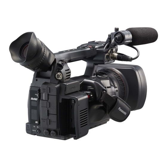
Operating Instructions
Memory Card Camera-Recorder
AG-HPX255P
Model No.
AG-HPX255EN
Model No.
Vol.2
ENGLISH
VQT4K98A (E)
Advertisement
Table of Contents

Related Manuals for Panasonic AGHPX255


Summary of Contents for Panasonic AGHPX255
-
Page 1: Operating Instructions
Register now!! This product is eligible for the P2HD 5 Year Warranty Repair Program. For details, see page 8 of Vol. 1. http://panasonic.biz/sav/pass_e/ Operating Instructions Vol.2 Memory Card Camera-Recorder AG-HPX255P Model No. AG-HPX255EN Model No. Volume Note that Operation Instructions Vol. 2 describes advanced operations of the Memory Card Camera-Recorder. - Page 2 • SDHC Logo is a trademark of SD-3C, LLC. • HDMI, the HDMI logo, and High-Definition Multimedia Interface are trademarks or registered trademarks of HDMI Licensing LLC. • Microsoft , Windows , and Windows Vista are either registered trademarks or trademarks of Microsoft ® ® ® Corporation in the United States and/ or other countries. • Screenshots are used in accordance with Microsoft Corporation guidelines. • Apple , Macintosh , and Mac OS are trademarks of Apple Inc., registered in the United States and other ® ® ® countries. • Other model names, company names, and product names listed in these operating instructions are trademarks or registered trademarks of their respective companies. • This product is licensed under the AVC Patent Portfolio License for the personal and non-commercial use of a consumer, and no license is granted or shall be implied for any use other than the personal uses detailed below. - To encode video in compliance with the AVC standard (“AVC Video”) - T o decode AVC Video that was encoded by a consumer engaged in a personal and non- commercial activity - To decode AVC Video that was obtained from a video provider licensed to provide AVC Video Additional information may be obtained from MPEG LA, LLC (http://www.mpegla.com).
-
Page 3: Before Use
Contents Volume 1 Read this first! (For AG-HPX255P) Menu Read this first! (For AG-HPX255EN) Basic operations of setup menus Read this first! (For AG-HPX255P/ Setup menu structure AG-HPX255EN) Outline of operations Reference Before use Specifications Operating precautions Precaution for use Accessories Optional units Description of parts Description of parts... -
Page 4: Table Of Contents
Contents (continued) Volume 2 Shooting Self-portrait shooting ........35 Scan reverse shooting ........35 Viewfinder ............6 Zebra pattern ........... 35 Using the viewfinder .......... 6 Center marker display ........36 Using the LCD monitor ........7 Safety zone markers ........36 Emphasizing Image Outlines ......7 Checking and displaying shooting status ..36 Adjusting the screen display ......8 Changing the image size ......... 37 Changing backlight brightness ......8 Optical Image Stabilizer ........37 Tally lamp ............. 9 DRS (Dynamic Range Stretcher) function ..37 Basic shooting operations ....... 10 FBC (Flash Band Compensation) ....38 Preparing to shoot ........... 10 Using the USER buttons ......... 39... - Page 5 Entering the user bits ........63 Precautions in 1394 connections ....107 Nonlinear editing with P2 card (PC mode: USB Setting the time code ........66 Externally locking the time code ...... 67 device) ............109 Outputting the time code externally ....70 Procedures for making connections to a Recording time codes and user bits ....71 personal computer ........109 Using a hard disk drive (PC mode: USB Playback host) .............. 111 Switching to the USB HOST mode .... 111 Basic playback operations .......
-
Page 6: Viewfinder
Viewfinder This camera has two viewfinders; one is a • The pixels of the LCD monitor are controlled miniature LCD in the viewfinder and the other is a to obtain high precision with 99.99 % of the retractable 3.45-type LCD. effective pixels. This leaves less than 0.01 % Use the viewfinder that best suits the application of pixels that may not light or may remain on and shooting conditions. all the time. These phenomena are normal and • The brightness and hue may differ between the will have no effect on the images you shoot. images appearing on the viewfinder and LCD • Screen burn-in may occur in the LCD monitor. monitor and those displayed on a TV monitor. However, this is not a defect. To see how the final images will appear, check • The following are all viewfinder phenomena, them on a TV monitor. and are not faults. Furthermore, they have no effect on recording with this camera or on When the LCD monitor is open, the viewfinder output signals. may not display anything. Close the LCD monitor. · Primary colors (green, blue, red) may be seen in cases such as moving your line of sight within the viewfinder. Using the viewfinder · At low temperatures, the screen may appear with a pink tint. ·... -
Page 7: Using The Lcd Monitor
Using the LCD monitor Emphasizing Image Outlines Emphasizing outlines of images in the viewfinder Set the POWER/MODE switch to ON. and on the LCD monitor makes it easier to focus. (Page 25 of Vol. 1) This function does not affect video output from the camera-recorder or video recorded by the camera- Open the LCD monitor. recorder. • It can open out to 90 degrees. Do not try to open it further as this will damage the Adjust EVF PEAK LEVEL and EVF PEAK FREQ camera-recorder. in the DISPLAY SETUP screen. DISPLAY SETUP EVF PEAK LEVEL EVF PEAK FREQ... -
Page 8: Adjusting The Screen Display
Viewfinder (continued) Adjusting the screen display • You can return the settings for EVF SETTING and LCD SETTING to the factory settings by Set the POWER/MODE switch to ON. selecting the item and pressing COUNTER (Page 25 of Vol. 1) RESET (if it is possible to change the item at that time). Press the MENU button. • The viewfinder display can be in color or black • For details on menu operation, refer to “Basic and white. (See the setup menus, DISPLAY operations of setup menus” (Page 28 of Vol. SETUP screen, EVF COLOR.) The resolution 1). is the same for both of them. • You can also use the corresponding buttons on the remote control. For details, see “Description of parts” (Remote control). Changing backlight brightness (Page 19 of Vol. 1) The brightness of the LCD monitor backlight can be adjusted between five different settings. -
Page 9: Tally Lamp
Tally lamp The tally lamp can be illuminated during recording by setting the TALLY LAMP item on the OTHER FUNCTIONS screen (Page 151) to any setting other than OFF. When the camera-recorder is in any of the following states, the tally lamp blinks. • When the remaining battery capacity runs out (4 blinks/sec.) Tally lamp • When the available recording space on the P2 (Rear) card or the battery power is low (1 blink/sec.) • When removing the P2 card during access (4 blinks/sec.) • When there is no recording space left on the P2 card (4 blinks/sec.) Tally lamp • When there is a warning for GENLOCK IN (Front) terminal signal distortion, system error, or a recording defect. (4 blinks/sec.) -
Page 10: Basic Shooting Operations
Basic shooting operations Preparing to shoot Shooting in auto mode Set the POWER/MODE switch to ON. Set the POWER/MODE switch to ON. (Page 25 of Vol. 1) (Page 25 of Vol. 1) • Check that the mode lamp (CAMERA) is Push the OPEN lever of the P2 card slot lighted red. cover downward () and slide to open (). Switch the AUTO/MANUAL switch to AUTO Insert the P2 card securely in the card slot. - Page 11 Under the following circumstances, even if you press the START/STOP button it may take some time until the writing to the P2 card finishes. For this reason, the operation will not be acknowledged if you press the START/STOP button too soon. • Stopped after only a short recording time • Stopped immediately after the recording has moved to a second P2 card...
-
Page 12: Checking The Shot Videos (Rec Check)
Basic shooting operations (continued) Checking the shot videos (REC CHECK) P2 card access lamps ■ Pressing the REC CHECK button after a recording CAMERA/PB/PC (USB HOST) mode will automatically play back the last two seconds of Lights green: the most recent clip. Data can be saved onto the cards or loaded from Holding down the REC CHECK button will allow them. you to play back up to 10 seconds. Blinks green (slow): Use this function to check that recording is No available space on card, card is performed normally. writeprotected. • The camera-recorder returns to recording Lights orange: standby mode after playback. Slot that is the object of recording. -
Page 13: Formatting P2 Cards
Formatting P2 cards On the thumbnails menu, select OPERATION and then FORMAT. (Page 91) Set the POWER/MODE switch to ON. • A screen such as the one shown below (Page 25 of Vol. 1) appears. Select the number of the slot into which you inserted the P2 card to Turn the POWER/MODE switch to set to PB/ be formatted. Select EXIT to cancel the THUMBNAIL mode (PB/THUMBNAIL lamp formatting. illuminates). • When you press the MENU button, the • Thumbnails are displayed. -
Page 14: P2 Card Recording Times
AVC-I 100 Approx. 5 min. • For the latest information not available in DVCPRO HD the Operating Instructions, visit the support AVC-I 50 Approx. 10 min. desk at the following website. DVCPRO50 http://pro-av.panasonic.net/ DVCPRO Approx. 20 min. P2 card recording times (When using one 64 GB card) Recording System mode Recording time format (codec) AVC-I 100 Approx. 64 min. -
Page 15: Remove The P2 Card
Remove the P2 card • If a P2 card is ejected during formatting or while its data is being accessed, “TURN POWER OFF” appears in the viewfinder and LCD monitor, and Push the OPEN lever of the P2 card slot a warning is indicated by the tally lamp. If this cover downward () and slide to open (). happens, turn the power off and back on again. · When a card is ejected during formatting: Check that the P2 card access lamp is not Format the card again. blinking orange. ·... -
Page 16: Using Sd/Sdhc Memory Cards
Using SD/SDHC memory cards You can use SD and SDHC memory cards (the Formatting SD memory card term “SD memory card” is used for both hereafter) to save and load SCENE files and USER files, and Set the POWER/MODE switch to ON. to upload clip meta data. (Page 58) (Page 25 of Vol. 1) Installing and removing the SD Turn the POWER/MODE switch to set to PB/ memory card THUMBNAIL mode (PB/THUMBNAIL lamp illuminates). Installation Press the MENU button. -
Page 17: Cautions In Using Sd Memory Cards
SDXC memory cards are not available for this product. SD (from 8 MB to 2 GB) SDHC (from 4 GB to 32 GB) For the latest information not available in the Operating Instructions, visit the P2 Support Desk at the following Web sites. http://pro-av.panasonic.net/ • SD memory cards must not be used or stored in an environment where they may be · Exposed to high temperatures/humidities; · Exposed to water droplets; or · Electrically charged. • Be sure always close the cover when using an SD memory card. -
Page 18: Using The Zoom Function
Using the zoom function This camera-recorder has a 22 x optical zoom On the remote control Press ZOOM/VOL to zoom with the motor drive. function. • Zoom speed is fixed at medium. Zoom with the zoom lever or the zoom ring. Zoom lever (handle side) Zoom ring ZOOM/VOL button Zoom lever (grip side) HANDLE ZOOM switch ZOOM switch Zoom lever Set the ZOOM switch to SERVO so that you can use the motor-driven zoom. T : Zoom in W : Zoom out Gently press the zoom button on the grip to zoom slowly, firmly press to zoom faster. Zoom lever (handle side) You can change the zoom speed on the handle zoom button by selecting one of three speeds with the HANDLE ZOOM switch. -
Page 19: Digital Zoom Function
Digital zoom function Assign the D.ZOOM function to USER MAIN or any of the USER 1 – 4 buttons to enable use of the digital zoom. (Page 39) Each press of the USER button to which D.ZOOM is assigned switches the zoom ratio in the following order: OFF (x1) → x2 → x5 → x10 → OFF (x1). • The viewfinder and the LCD monitor indicate the zoom ratio when a setting other than OFF (x1) is selected. • “Using the USER buttons” (Page 39) Please take note of the following points regarding use of the digital zoom function. • Digital zoom is not available when the DRS (dynamic range stretcher) function (Page 133) or the SCAN REVERSE function (Page 136) is running. • The FBC (flash band compensation) function (Page 38) is not available when the digital zoom function is running. The FBC function becomes available again when digital zoom is switched back to OFF. • Operating the DRS function or SCAN REVERSE function when the digital zoom function is running switches the digital zoom... -
Page 20: Shooting In Progressive Mode
Shooting in progressive mode In 1080i and 480i (576i) mode, this unit can • In 24P/24PA, 24PN (native recording) and in perform progressive shooting when CAMERA 30PN/25PN (native recording) at 720P, the MODE of the setting menu is set to 24P, 24PA, or camera starts recording in 5-frame, 4-frame 30P (25P). and 2-frame segments, respectively. For When performing progressive shooting, the this reason, to continue recording clips in recording format can be set to native (which uses a system mode using a different recording the camera’s shooting frame rate as is) or standard... -
Page 21: Recording With Variable Frame Rate (Vfr)
Recording with Variable Frame Rate (VFR) In 1080i and 720P mode, this unit can shoot Note the following about native VFR using frame skipping (under cranking) and high recording. speed recording (over cranking). You can select • Pre-recording, loop recording, interval native (PN) recording mode and standard (OVER) recording, one-shot recording, and one-clip recording. recording are not available. • 1394 output is not available during Native VFR recording recording and recording standby. -
Page 22: Standard Vfr Recording (Pulldown Recording)
Recording with Variable Frame Rate (VFR) (continued) Standard VFR recording • With AVC-Intra or DVCPRO HD in 1080i, (pulldown recording) clips are recorded as 60i, 60P (50i, 50P) with pull down information not recorded. In 1080i or 720P mode, set REC FORMAT on • Audio playback is disabled when a frame the setting menu SYSTEM SETUP screen to rate converter is used to extract active... -
Page 23: Using Progressive Mode And Vfr Recording Function
Using progressive mode and VFR recording function Standard speed for film production Screen production normally requires a 24 fps (24 frames per second) frame rate (normal speed) for screening a film. Making the settings described below will provide film-quality playback. The 720P progressive mode and cine-like gamma will make video look like it was shot with a film camera-recorder. Standard settings for film production SYSTEM MODE settings Recording frame rate SYSTEM MODE Other settings AVC-I 100/24PN REC FORMAT (AVC-I 50/24PN) 720-59.94P (DVCPROHD/24PN) AVC-I 100/24PN 24 frames REC FORMAT (AVC-I 50/24PN) (DVCPROHD/60i) 1080-59.94i CAMERA MODE 24P, 24PA... - Page 24 Recording with Variable Frame Rate (VFR) (continued) Shooting at standard speed for producing commercials and TV programs When producing videos for display on a television screen such as HDTV/SDTV broadcast, a frame rate of 30 fps (30 frames per second), 25 fps (25 frames per second) for 50 Hz, is standard (x1). The settings below allow you to obtain the kind of playback used for broadcast programs. This permits film-like video recording of commercials and music clips that also provide a frame rate suitable for broadcasting. Standard settings for producing commercials and dramas SYETEM MODE settings Recording frame rate SYSTEM MODE Other settings AVC-I 100/30PN REC FORMAT (AVC-I 50/30PN) 720-59.94P (DVCPROHD/30PN)
- Page 25 Undercranking effects This effect produces the quick motion often used for showing clouds drifting across the sky, crowds of people swarming past a solitary standing individual, a kung fu demonstration and other performances. For example, selecting a VFR recording frame rate of 12 fps when shooting at a 24P recording format yields a fast-motion effect of approx. 2x normal speed. Standard setup for undercranking effects SYSTEM MODE settings Recording frame rate SYSTEM MODE Other settings AVC-I 100/24PN REC FORMAT (AVC-I 50/24PN) 1080-59.94i 1 to 22 frames FRAME RATE Set to 23 frames or less AVC-I 100/25PN REC FORMAT (AVC-I 50/25PN) 1080-50i 1 to 24 frames FRAME RATE Set to 24 frames or less AVC-I 100/24PN REC FORMAT (AVC-I 50/24PN) (DVCPROHD/24PN) 720-59.94P 1 to 22 frames FRAME RATE Set to 22 frames or less...
- Page 26 Recording with Variable Frame Rate (VFR) (continued) Overcranking effects Overcranking produces slow-motion playback, which is frequently used in climax scenes, or for dramatic effects like car chases and action scenes. For example, selecting a recording frame rate of 60 fps when shooting a 24P recording format yields a slow-motion effect that is 2.5 times normal speed. Shooting 720P progressive video will produce smooth and highquality slow-motion. Furthermore, with 1080i, a slow motion effect of 1.25 can be gained if you set the recording frame rate to 30 fps when recording was performed using 24P, a recording format for specifying the playback frame rate. Standard setup for overcranking effects SYSTEM MODE setup Recording frame rate SYSTEM MODE Other settings AVC-I 100/24PN REC FORMAT (AVC-I 50/24PN) 1080-59.94i 25 to 30 frames FRAME RATE Set to 25 frames or more AVC-I 100/24PN REC FORMAT (AVC-I 50/24PN) (DVCPROHD/24PN) 720-59.94P 25 to 60 frames...
-
Page 27: Flow Effect Shooting
Flow effect shooting This way of shooting provides a flow effect and may, for instance, be used to shoot a subject on a far side of a road with a stream of fast-moving cars as the flow, in such a way that the stationary subject comes into focus though the cars. Set SYSTEM MODE on the setting menu SYSTEM SETUP screen to 1080-59.94i (50i), REC FORMAT to AVC-I 100 (50)/60i (50i) or DVCPRO HD/60i (50i), and VFR to ON. Set FRAME RATE to a low value suitable for the shooting purpose. Setting can be performed in the same way for 720P. Press the START/STOP button. -
Page 28: Shooting In Manual Mode
Shooting in manual mode Set the unit to manual mode when manually PUSH AUTO button adjusting the focus, iris, gain and white balance. While pressing the PUSH AUTO button, the automatic focus can be set quickly. Switching to manual mode Switching to manual focus assist mode Slide the AUTO/MANUAL switch to MANUAL to To change from the manual focus mode to the switch to the manual mode. manual focus assist mode, set MF ASSIST to ON on the viewfinder and LCD go out.) on the setting menu SW MODE screen. • You can make coarse adjustments to the focus in manual focus assist mode by turning the focus ring about half the amount you would turn it in manual focus mode. • Fine adjustment is made automatically after you operated the focus ring. • If the focus differs considerably form the manually set focus, the focus may not be set correctly. • Automatic adjustment is not performed until you AUTO/MANUAL switch operate the focus ring for the next time. -
Page 29: Using Focus Assist Function
Using focus assist function This function magnifies only the image To easily focus an image, expanded display or at the center of the LCD monitor and In Red display can be selected with the FOCUS viewfinder. ASSIST button, and the focus bar display can be In VIDEO OUT, SDI OUT, and HDMI OUT, the used. center of the image is not magnified and status indications do not appear. FOCUS ASSIST button When you press the FOCUS ASSIST button, the image contour has red edges or the screen Displaying the focus bar (FOCUS BAR): center of the LCD monitor is enlarged to set the You can display the focus bar by setting FOCUS focus easily. The screen display of the viewfinder BAR on the DISPLAY SETUP screen of the or the LCD monitor that appears when you press settings menu to ON. -
Page 30: Iris Adjustments
Shooting in manual mode (continued) Iris adjustments Adjusting the gain When the display is dark, increase the gain to brighten the display. IRIS ring IRIS button GAIN switch Use the AUTO/MANUAL switch to switch to the manual mode. (Page 28) Use the AUTO/MANUAL switch to switch to Press the IRIS button to switch how to the manual mode. -
Page 31: Using Super Gain
Using super gain You can increase the gain level further when shooting in dark space. Set SUPER GAIN on the setting menu SW MODE screen to 24 dB, 30 dB or BOTH. Cycles to the next value in the order 24 dB → 30 dB → OFF when pressing USER button in BOTH. You can switch to the selected gain by pressing a USER button to which S GAIN has been assigned. • “Using the USER buttons” (Page 39) • In variable frame rate (VFR) mode, super gain is not available when the frame rate is set to 4 frames or less. • AGC is not available when super gain is selected, even if AUTO/MANUAL is set to AUTO. Light intensity adjustments Use the ND FILTER dial to change the ND Filter used (filter to change light intensity). OFF: ND filter is not used. 1/4: Cuts light intensity by up to about 1/4. 1/16: Cuts light intensity by up to about 1/16. 1/64: Cuts light intensity by up to about 1/64. ND FILTER dial... -
Page 32: Adjusting The White Balance And Black Balance
Adjusting the white balance and black balance To record high-quality video with the AG-HPX255P/ Set the GAIN and WHITE BAL switches. EN, the black and white balances must be adjusted • For the WHITE BAL switch, select A or B as according to conditions. a position to save the adjustment value. If white balance and black balance adjustments Adjust the ND FILTER dial according to the are made while the video image is distorted light conditions. due to GENLOCK, the adjustments may not For examples of ND FILTER dial, see “Light be correct. Wait for the video image to return intensity adjustments” (Page 31). to normal before performing white balance and black balance adjustments again. Place a white pattern at a point where the light conditions match those for the light source of the subject. - Page 33 Setting auto tracking white balance (ATW) The adjustment will take effect in a few This camera-recorder is equipped with an auto seconds, and the following message will tracking white balance (ATW) function that appear: automatically adjusts the white balance of images • The adjusted value is automatically stored in in accordance with lighting conditions. the selected memory (A or B). The ATW function can be assigned to the WHITE AWB A OK 3.2K BAL switch B by setting the menu option ATW in the SW MODE screen to B ch. • “C TEMP+7” to “C TEMP-7” will appear when Also, you can allocate the ATW function to USER COLOR TEMP of the scene file is set to the MAIN or USER buttons 1 to 4. value other than 0.
-
Page 34: Adjusting The Black Balance
Adjusting the white balance and black balance (continued) Adjusting the black balance • During a black balance adjustment, light is The black balance must be adjusted when: automatically cut off. • You use your AG-HPX255P/EN the first time. • Black balance adjustment is not available • Your AG-HPX255P/EN has not been used for during recording. some time. • Pressing the START/STOP button during • The ambient temperature has changed ABB adjustment will not start recording on substantially. -
Page 35: Shooting Techniques For Different Targets
Shooting techniques for different targets Low-angle shooting Scan reverse shooting Low-angle shooting can be performed using the By setting SCAN REVERSE on the setting menu handle side START/STOP button by releasing SYSTEM SETUP screen to ON, video can be () the hold switch on this button from the HOLD vertically/horizontally inverted when displaying and position. recording. • To prevent accidental operation of the START/ STOP button on the handle side when not in use, Zebra pattern set the hold switch to HOLD. The AG-HPX255P/EN can display two zebra patterns. Turning the ZEBRA switch on displays the zebra pattern set in the menu in the viewfinder and LCD HOLD switch monitor. A menu setting makes it possible to also display the zebra pattern on video output via the START/STOP button (handle side) VIDEO OUT connector. ZEBRA button Use the DISPLAY SETUP screen to set the level of zebra pattern display. (Page 147) Self-portrait shooting... -
Page 36: Center Marker Display
Shooting techniques for different targets (continued) Checking and displaying shooting Center marker display status A center marker is displayed when the menu option MARKER in the DISPLAY SETUP screen is set to ON. (Page 147) DISP/MODE CHK button The center marker display appears only on the LCD monitor and in the viewfinder. It When you hold down the DISP/MODE CHK is not superimposed on signals output via button during recording standby or recording, all the VIDEO OUT, SDI OUT and HDMI OUT the information including the setting status of the... -
Page 37: Changing The Image Size
Changing the image size Optical Image Stabilizer When recording in 480i/576i mode, you can Use the Optical Image Stabilizer (OIS) to reduce change the size (aspect ratio) of the images that the effects of camera-recorder shake when you record. shooting by hand. Select the aspect ratio in the setup menus, Press the OIS button to turn the function on and SYSTEM SETUP screen, ASPECT CONV. (Page 137) off. • Refer to the section “Basic operations of setup appears on the viewfinder and LCD monitor menus” (Page 28 of Vol. 1) for menu operation. when the Optical Image Stabilizer function is ON. Turn the function off when using a tripod for more SIDE CROP: natural images. Recorded in the regular 4:3 aspect ratio. The left and right edges of the image are cut. OIS button LETTER BOX: Recorded in the 16:9 aspect ratio. Black bands are recorded at the top and bottom of the image. • This function will not be as effective when the When LETTER BOX is selected, black bands vibration is severe or when tracking a moving are not displayed at the top and bottom of the subject. -
Page 38: Fbc (Flash Band Compensation)
Shooting techniques for different targets (continued) FBC (Flash Band Compensation) Using FBC This camera-recorder comes with a function to FBC goes on when the brightness of the compensate for and minimize light band (flash lower half of the image differs markedly from band) interference that occurs with the MOS the previous half, which could be caused by imager when shooting in an environment where light from a camera flash or other strong light flash photography is taking place. -
Page 39: Using The User Buttons
Using the USER buttons SHOT MARK: Assigns the shot marker function. (Page 41) You can allocate the selected function to USER MAG A. LVL: MAIN and USER buttons 1 to 4. Assigns a function that magnifies the audio level USER1 – 3 button meter. (Page 55) LVL METER: Allocates a function that switches between CH1/2 and CH3/4 for the audio level meter display and audio channel for headphones, built-in speaker, AUDIO OUT terminal output, and HDMI OUT output while the button is held down. PRE REC: Assigns a function that turns the PRE REC USER MAIN button function on and off. (Page 44) USER4 button WFM: Selectable Functions Assigns a function that switches WAVE FORM display. SPOTLIGHT: The WAVE FORM display is selected using the Assigns auto iris control on/off for spotlight. -
Page 40: Backlight Compensation
Shooting techniques for different targets (continued) Backlight compensation Adjusting the volume while shooting Press the USER button you have allocated to the BACKLIGHT feature when shooting subjects lit from the back. BACK appears on the screen. Backlight compensation adjusts the iris so the subject doesn’t come out dark. If you press the USER button again, backlight compensation is cancelled. • “Using the USER buttons” (Page 39) Color bars Adjusting the volume Press the BARS button in CAMERA mode to output a color bar screen to a television or monitor so you can adjust them. Press the button again to turn the feature off. If you are monitoring the sound through BARS button headphones while shooting, you can adjust the The color bar screen turns off and camera-recorder image appears. volume with the PAGE/AUDIO MON/VAR button. • Adjustment of input audio level is performed with the AUDIO LEVEL knob. (Page 54) Backup recording If you have connected equipment to the 1394... -
Page 41: 2-Slot Continuous Recording
2-slot continuous recording Shot mark function If you insert two P2 cards into the two card slots, The marks attached to the thumbnails of clips this function allows you to record continuously on are called shot marks. On the thumbnail screen the two cards. monitor you can select only those clips with a shot You can also record continuously on three or more mark and display them or play them back. cards by replacing one card while data is being • “Switching the thumbnail display” (Page 80) recorded on the other. (Hot swap recording) During recording, when you press the USER button However, depending on when the P2 card is to which the SHOT MARK function has been inserted into an empty slot (immediately after allocated, MARK ON appears in the LCD monitor prerecording, or before or after continuous or the viewfinder, and a shot mark is set for the recording spanning two slots), there may be a thumbnail of the clip being recorded. If you press delay in recognizing the P2 card. the button again, the shot mark is released. We recommend inserting the P2 card while there • “Using the USER buttons” (Page 39) is at least one minute remaining on the card that is • A shot mark added during a pause after recording. -
Page 42: Text Memo Recording
Shooting techniques for different targets (continued) Text memo recording LAST CLIP DELETE function This function adds text memos at the video points Assign LAST CLIP to any of the USER MAIN or on the clip now being recorded or played back. USER 1 – 4 buttons to enable a convenient way to When you press the USER button to which the delete the last recorded clip. TEXT MEMO function has been allocated, the text Pressing the USER button to which LAST CLIP memo will be recorded at that point. was assigned displays a YES/NO confirmation • “Using the USER buttons” (Page 39) dialog on the screen. Select YES, and the last recorded clip is deleted On the thumbnail screen you can select only those and “LAST CLIP DELETE OK” is displayed. clips where text memos have been added, and • “Using the USER buttons” (Page 39) then either display those clips or play them back. • “Switching the thumbnail display” (Page 80) • Select NO to cancel clip deletion. You can record up to a hundred text memos per • Clips cannot be deleted even when you press the clip. -
Page 43: Using Special Recording Modes
Using special recording modes During P2 card recording, the following special recording modes can be enabled from the RECORDING SETUP screen: pre-recording, interval recording, one-shot recording, loop recording, and one-clip recording. These recording modes (excluding one-clip recording) are available only with the following settings. One-clip recording mode is available in all recording modes, except when VFR is turned ON. SYSTEM MODE REC FORMAT Other conditions DVCPROHD/60i • Set CAMERA MODE to 60i or 30P. 1080-59.94i AVC-I 100/60i • Turn VFR OFF. AVC-I 50/60i DVCPROHD/50i 1080-50i AVC-I 100/50i • Turn VFR OFF. AVC-I 50/50i DVCPROHD/60P 720-59.94P AVC-I 100/60P • Turn VFR OFF. AVC-I 50/60P DVCPROHD/50P 720-50P AVC-I 100/50P • Turn VFR OFF. AVC-I 50/50P DVCPRO50/60i 480-59.94i... -
Page 44: Pre-Recording (Pre Rec)
Using special recording modes (continued) Pre-recording (PRE REC) Interval recording (INTERVAL REC) This function is used to start recording a certain This function is used to record 1 frame at the time number of seconds (approx. 3 seconds for HD interval set in the INTERVAL TIME item. recordings or approx. 7 seconds for SD recordings) before actual recording starts. 1 frame 1 frame 1 frame recording recording recording Starting recording Stopping recording (time) (time) Actual recording Set INTERVAL Set INTERVAL time TIME setting TIME setting PRE REC time... -
Page 45: One-Shot Recording (One Shot Rec)
One-shot recording (ONE SHOT REC) • The pre-recording and one-clip recording This function records a single shot at each unit of functions are not available. time which has been set. • Sound is not recorded. • Data recorded (until the stop recording) in Check that the SYSTEM SETUP screen is this mode is recorded as a single file. set up as described on page 43. -
Page 46: Loop Recording (Loop Rec)
Using special recording modes (continued) Loop recording (LOOP REC) • Use two P2 cards with at least one minute • When two P2 cards are inserted in the P2 card of remaining recording time. slots, each card is recorded in succession. • The mode check screen shows standard • When there is no longer any space left on the recording time depending on recording second cards, recording starts over from the first format as remaining P2 card time. -
Page 47: One-Clip Recording (One Clip Rec)
One-clip recording (ONE CLIP REC) • In addition to the aforementioned steps, the Instead of creating a new clip for each recording following ends combining to the clip and session (i.e., operation from REC start to stop), subsequent recordings use a new clip. this mode compiles images from multiple recording · When the power is turned off sessions into a single clip. · When the P2 card with the previous recording is removed · When the P2 card is formatted or the clip is REC Start REC Start REC Start deleted (when the previous combined clip does not exist) - Page 48 · The following Menu items, related to the reading/ writing of the SD memory card and reading of the settings file, cannot be executed. LOAD/SAVE/INIT in SCENE FILE, all options in CARD FUNCTIONS, USER FILE and MENU INIT in OTHER FUNCTIONS · The following thumbnail menu items cannot be selected and executed. OPERATION→COPY • The processing time to complete the recording may take a little more time than normally to allow the clip to be combined with subsequent recordings. • The fade process does not work on discontinuous audio during playback where the recordings are combined within the clip. • If non-linear editing software is used on clips with multiple combined recordings, the software may not operate normally (as of Jun. 2012). For the latest information on software that has been confirmed to work with these types of clips, visit the support desk at the following website. http://pro-av.panasonic.net/...
-
Page 49: Adjusting The Shutter Speed
Adjusting the shutter speed Setting SHUTTER mode Shutter speed is set using the SHTR/F.RATE dial and DIAL SEL button. As well as the shutter speed, you can use the Push DIAL SEL to select SHUTTER mode. SHTR/F.RATE dial to select settings for synchro scan and frame rate. Push the SHTR/F.RATE dial. • The SHUTTER mode changes ON/OFF. Using SHTR/F.RATE dial • The shutter speed changes by turning the SHTR/F.RATE dial in the shutter mode ON. (Page 50) • Remember that the faster the shutter speed, the lower the sensitivity. • It will take longer to focus when the shutter speed has been reduced so it is recommended that the unit be secured to a tripod, etc. for use. • The screen may be distorted when changing SHTR/F.RATE dial the SYNCHRO SCAN or SHUTTER setting. -
Page 50: Setting Synchro Scan Mode
Adjusting the shutter speed (continued) If all modes and speeds are available, the display Setting SYNCHRO SCAN mode changes in the following order: Select SYNCHRO SCAN in the SHUTTER ■ When SYSTEM MODE is set to 1080-59.94i, mode. 720-59.94P, 480-59.94i • Turn the SHTR/F.RATE dial, the value For 60i and 60P recording displayed after 1/2000 is the current SYNCHRO SCAN setting value. Select this (1/15) (1/30) 1/60 1/100 1/120 value. -
Page 51: Setting Frame Rate Mode
Setting FRAME RATE mode Press DIAL SEL button to select FRAME RATE function. When VFR is ON, the frame rate indicator on the viewfinder and LCD monitor flash as shown in the diagram below, indicating that you can alter the frame rate. 3 0 : 2 4 P N C H 1 . 2 • If they are not flashing, VFR mode is OFF. Press the SHTR/F.RATE dial to set VFR mode to ON. VFR mode switches between ON/OFF each time the SHTR/F.RATE dial is pressed. The FRAME RATE is set by turning the SHUTR/F.RATE dial. -
Page 52: Switching Audio Input
Switching audio input During shooting, you can record up to four INPUT1 LINE/MIC switch channels of sound. You can also switch the input INPUT1 switch sound to be recorded on each of the channels to (MIC POWER +48V) the built-in microphones, external microphones or INPUT2 LINE/MIC switch audio equipment connected to camera-recorder. INPUT2 switch (See table below.) (MIC POWER +48V) SELECT CH1 recording CH3 recording switch INT (L) Built-in microphone INPUT1 switch selection is valid (LINE/MIC select) INPUT1 INPUT1 switch Built-in microphone selection is valid (LINE/MIC select) INPUT2 INPUT2 switch... -
Page 53: Using Another Microphone And Audio Equipment
Using another microphone and audio • Select the input to be recorded on CH1 and equipment CH3 with the AUDIO CH1 SELECT switch, and select the input to be recorded on CH2 Connect an external microphone or audio and CH4 with the AUDIO CH2 SELECT switch. equipment to the AUDIO INPUT 1/2 (XLR, (Page 52) 3 pin) terminal. (Page 101) • When signals from an external microphone are to be input to CH1 and CH2, connect the Use the INPUT 1/2 switch to switch the external microphone to the AUDIO INPUT 2 audio input. -
Page 54: Adjusting The Recording Level
INT MIC OFF • To adjust the volume of the sound for monitoring, see “Adjusting the volume while shooting” (Page 40). Check the recording level prior to shooting. • The recording level is set higher than for To adjust the recording levels for Audio Channels 1 Panasonic’s broadcast-use camera-recorder and 2, follow the steps below. recorders (AJ series, AG-HPX500, 370 or 300 series). Set AUDIO OUT on the setting menu AUDIO SETUP screen to CH1/CH2 and confirm that the display is 1, 2, so that the audio level meter display indicates CH1, CH2. -
Page 55: Ch3 And Ch4 Recording Levels
CH3 and CH4 recording levels (Only for AG-HPX255EN) 1 2 : 3 4 : 5 6 : 2 3 9 9 9 min The setup conditions and limiter settings specified U L L P A U S E 1 - C L I P U S E R - 1 in the menu options AUTO LEVEL CH3 and AUTO ... -
Page 56: Using Scene Files (Scene File Data)
Using scene files (Scene File Data) Each position of the SCENE FILE dial stores Changing scene file settings settings for specific shooting situations. ■ Example 1: Change the name of the scene When shooting, you can retrieve the necessary file file. instantly using scene file dial. SCENE FILE dial Turn the scene file dial, then select the scene file to be changed. Select the menu option NAME EDIT in the SCENE FILE screen, then press the Operation lever in the ▲... - Page 57 • Pressing the MENU button fixes the current settings and closes NAME EDIT. • Values that have been fixed are maintained SAVE even if the power is switched OFF or the COMPLETED ! dial is changed. The settings for all items in scene files are also maintained in the same way. • After changing the scene file settings, to return to the settings to the previously saved values, ■ Example 2: Save the F3 scene file to the select LOAD in step 2 and perform the operation camera-recorder. described in step 3. • To return the scene file settings to their factory Select the menu option LOAD/SAVE/INIT in defaults, select INITIAL in step 2 and perform the the SCENE FILE screen, then press the SET operation described in step 3.
-
Page 58: Saving Scene Files And Other Settings On Sd Memory Cards
Using scene files (Scene File Data) (continued) Saving scene files and other settings Push the Operation lever in the ▲ ▼ on SD memory cards direction, and select file number (1 to 4). • Press the SET button again to confirm the You can save up to four scene file settings or other setting. settings as files on an SD memory card, and you can also load them from the card. SCENE FILE (SD CARD) • Current scene file settings are automatically FILE SELECT READ... - Page 59 To title a file Perform steps 1 to 5. Set the filename with 8 characters by using Operation lever. • ▲ ▼: Character shift ◄ ►: Character selection SET: Character fix • Characters that can be set space (□) → alphabet (A to Z) → numerics (0 to 9) → symbols (; : < = > ? @ [ \ ] ^_-./) • If the RESET button is pressed when the filename has been set, the characters are cleared. BARS SHUTTER SPEES SELECT CH1 SELECT CH2 SELECT INPUT1 INPUT2 START/ DATE/ PHOTO INT(L) INT(R) STOP TIME SHOT INPUT1 INPUT2 INPUT2 MIC POWER+48V...
-
Page 60: Configuration Of Setup Data Files
Using scene files (Scene File Data) (continued) Configuration of setup data files This camera makes it possible to save a scene file to each of the F1 to F6 positions on the SCENE FILE dial. Use of an SD memory card makes it possible to save up to four of the F1 to F6 files on an SD card for later retrieval. The setting menu values can be stored as a user file in the camera-recorder and up to four files can be stored on the SD memory card. The setting data files are configured as shown below. AG-HPX255P/AG-HPX255EN SD CARD SCENE FILE SCENE FILE SCENE FILE SCENE FILE (Factory defaults) (Current operating status values) (Saved camera values) (SD CARD) F1 Default value F1 Current value F1 Saved value... -
Page 61: Using Time Data
Using time data Time data overview The camera-recorder provides time data such as time codes, user bits, time of day (real-time) data, ■ Time code which is recorded on each frame alongside video You can switch between REC RUN and FREE data. It is also recorded as data in clip metadata RUN from the setup menu. (Page 141) files. FREE RUN: The time code advances constantly whether the Counter setting and display camera-recorder is on or not just like time itself. Recording using a slave-locked time code input Pressing the COUNTER button to view the counter to the TC IN/OUT or DVCPRO/DV connectors is displays the counter value on the time code also possible. indicator in the LCD and in the viewfinder. (Page 121) REC RUN: The counter value is indicated in “Hour : Minute . The time code advances only during recording. Second” format. The counter value is not displayed This will enable continuation of time codes in during playback. previously recorded clips and when the power The menu option REC COUNTER in the DISPLAY is turned off or new P2 cards are inserted to SETUP screen can be set to display two types of continue recording. -
Page 62: Setting User Bits
Using time data (continued) ■ Date (real time) • A slave relationship, once started, continues even after input from the TC IN/OUT or DVCPRO/DV • The built-in clock calculates the year, month, day connector ends. Note that the following events and time from the internal clock to display on release user bit slave status. video in the LCD, viewfinder and VIDEO OUT and other video output. · When a UB MODE option is set to something • The internal clock is not only used to calculate other than EXT. the free run time code when the power is off and · When UB PRESET is performed to set the user bit year, date and time, but also · When switching to 1394 in the menu option to set file creation dates when clips are recorded REC SIGNAL in the SYSTEM SETUP screen. that determine the order of thumbnails and · Turning the power off. playback order. • The internal user value retains the slave values • It is also used for generating clip metadata and even after slave release. UMID (Unique Material Identifier). -
Page 63: Entering The User Bits
Entering the user bits Use Operation lever to set the user bits. The user bits allow information, including memos UB PRESET that use up to eight-digit hexadecimal numbers (date and time), to be recorded in the Subcode +/- : PUSH area. SEL : PUSH PRESET : PUSH SET PUSH MENU TO RETURN ► direction: S hifts the target (highlighted) digit to the right. ◄ direction: S hifts the target (highlighted) RESET button digit to the left. - Page 64 Using time data (continued) Frame rate information recorded in user bits 1080i, 480i, 576i mode The frame rate value of video data captured and Frame rate: 24P over 60i (2:3) recorded at a frame rate set in the menu option First field of updated frame rate FRAME RATE or other options in the SYSTEM SETUP screen can be recorded in the user bits and Time code digit be used in editing equipment (personal computer editing software). Video This type of data is recorded in VITC UB at all Ao Ae Bo Be Bo Ce Co De Do De Ao Ae Bo Be Co De Do De Ao Ae Bo Be Bo Ce Co De Do De times.
- Page 65 720P mode Frame rate: 24P over 60P (2:3) Updated frame Time code digit Video A A B B B C C D D A A B B D D D A A B B B C C D D D Updated frame information Frame rate: 30P over 60P (2:2) 25P over 50P (2:2) Time code digit Video...
-
Page 66: Setting The Time Code
Using time data (continued) Setting the time code Press SET on the Operation lever and confirm the time code setting value and Switch the menu option TC MODE and TCG you leave the time code setting screen. on the RECORDING SETUP screen to set the mode of the time code. -
Page 67: Externally Locking The Time Code
■ Externally locking the time code Example 2: Connecting two or more AG- HPX255P/EN with one another, with one The time code generator built into your AG- being used as the reference device. HPX255P/EN may be locked to an external generator. It is also possible to lock an external Reference device Slave device time code generator to the internal generator. Connections for externally locking the time code (examples) As illustrated, both the reference video signals and the time code must be input. - Page 68 Using time data (continued) To externally lock the time code Setting the user bits when the time code is externally locked Follow the steps below. To externally lock user bits, set the setting menu Turn the POWER/MODE switch to ON. UB MODE (RECORDING SETUP screen) to EXT. Regardless of an FREE RUN or REC RUN setting, Set TCG on the setting menu RECORDING the time code is slaved to user bit values input to SETUP screen to FREE RUN. the TC IN/OUT connector.
- Page 69 GENLOCK and time code input/output connection and setup GENLOCK input and camera-recorder Camera- Camera-recorder operating conditions output phase recorder setup (In phase: √ Out of phase: ×) Video and reference Recording VIDEO OUT, signal to be output GENLOCK input GL PHASE SDI OUT (HD) TC OUT format...
-
Page 70: Outputting The Time Code Externally
Using time data (continued) Outputting the time code externally To output time code from the camera-recorder’s TC OUT connector to a VTR or other recording device in sync with camera-recorder picture or playback picture, set the setting menu TC VIDEO SYNC (OUTPUT SEL) to VIDEO OUT. Set the menu option GL SELECT to HD SDI or COMPOSITE as required by supplied video output in the OTHER FUNCTIONS screen and the menu option TC OUT to TCG/TCR in the OUTPUT SEL screen. AG-HPX255P/EN SDI OUT or VIDEO OUT VTR, etc. When the setting menu TC VIDEO SYNC is set to VIDEO OUT, the time code is output via TC IN/OUT in tune with VIDEO OUT delay. -
Page 71: Recording Time Codes And User Bits
Recording time codes and user bits When SYSTEM MODE is set to 1080-59.94i, 720-59.94P, 480-59.94i Displayed System setting status Recorded TC Output TC Recorded UB Output UB LTC and TC IN/OUT LTC UB VITC UB SYSTEM CAMERA FRAME VITC TC tc (24/30 REC FORMAT VITC TC OUT... - Page 72 Using time data (continued) Displayed System setting status Recorded TC Output TC Recorded UB Output UB LTC and TC IN/OUT LTC UB VITC UB SYSTEM CAMERA FRAME VITC TC tc (24/30 REC FORMAT VITC TC OUT LTC UB VITC UB connector embedded embedded...
- Page 73 When SYSTEM MODE is set to 1080-50i, 720-50P, 573-50i Displayed System setting status Recorded TC Output TC Recorded UB Output UB LTC and TC IN/OUT LTC UB VITC UB SYSTEM CAMERA FRAME VITC TC tc (24/30 REC FORMAT VITC TC OUT LTC UB VITC UB connector...
-
Page 74: Basic Playback Operations
Basic playback operations Turn the POWER/MODE switch to ON. While holding down the lock release button, turn the POWER/MODE switch to the ON position. Turn the POWER/MODE to illuminate the PB/THUMBNAIL operation lamp. The camera-recorder is now in the PB/ THUMBNAIL mode. • Each time you press the button, the mode changes as below. Mode lamp (PB/THUMBNAIL) PB/THUMBNAIL CAMERA Turning and holding the POWER/MODE switch downward for about 2 seconds after entering PB/THUMBNAIL mode switches to PC (Personal Computer connection) mode. Lock release button (Page 109) POWER/MODE switch For details on playing back clips using thumbnails, see page 75. -
Page 75: Thumbnail Operations
Thumbnail operations A clip is a data group that includes the images and voices created from one shooting session, together with additional information such as text memos and meta data. On this unit, thumbnails of all clips are displayed on the LCD monitor by switching to PB/THUMBNAIL mode. You can carry out the operations below by using the Operation lever on the thumbnail screen. • Playback, delete, copy or restore the clip. • Add or delete a shot mark and a text memo on the clip thumbnail. • Copy part of a clip by using the text memo. • Change the thumbnail image by using the text memo. • Format P2 cards and SD memory cards. • Uploading and editing clip metadata from the SD memory card... -
Page 76: Thumbnail Manipulations Overview
Thumbnail operations (continued) Thumbnail manipulations overview Thumbnail screens are configured as follows: THUMBNAIL OPERATION PROPERTY ALL CLIP DELETE CLIP PROPERTY SAME FORMAT CLIPS FORMAT SELECTED CLIPS REPAIR CLIP MARKED CLIPS RE-CONNECTION TEXT MEMO CLIPS COPY EXCH. THUMBNAIL EXIT CARD STATUS SLOT CLIPS INDICATOR SET UP DATA DISPLAY EXIT DATE FORMAT... -
Page 77: Thumbnail Screen
1. Display Mode Thumbnail screen The type of the thumbnail indicated on the The thumbnail screen is displayed on the LCD display and the types of the other information monitor when you turn the POWER/MODE switch screens are indicated. downward and switch to PB/THUMBNAIL mode. ALL: Turn the POWER/MODE switch again to return to Display all clips. CAMERA mode. SAME FORMAT: After changing from CAMERA mode to the Clips in the same format as the system format thumbnail screen, all clips are displayed on the (SYSTEM MODE item, REC FORMAT item) thumbnail screen. are shown. Pressing the MENU button allows you to navigate • Refer to page 135 for each item. the thumbnail menu. SELECT: The clips selected with the SET button are shown. MARKER: Display clips with shot marks. TEXT MEMO: Display clips with text memo data. SLOT n: Display clips in the specified P2 card. (n: 1 or 2, which indicates Slots 1 or 2.) UPDATING..: Indicated when the camera-recorder is updating the screen or reading data. When the screen is being updated, the rotating icon... - Page 78 Thumbnail operations (continued) 2. Slot numbers and HDD status 8. Clip Number The numbers set by the camera-recorder for all This section indicates on which P2 card the the clips recognised correctly by the P2 card. pointed clip is recorded. The number of the These numbers are allocated in chronological slot that contains the appropriate P2 card is indicated in yellow. If the clip is recorded on order, by shooting dates and times. more than one P2 card, then the numbers of If clips cannot be played because of different all slots that contain the appropriate cards are recording formats, they are displayed in red. indicated. The numbers of the other slots are Defective Clip Indicator and shown in white if they contain P2 cards. Unknown Clip indicator When the following P2 card is inserted, the slot This marker is displayed for defective clips, number is displayed with a pink frame. which may result from a variety of causes, e.g., • RUN DOWN CARD powering-down during recording. (A P2 card on which the maximum number of Clip with yellow defective clip indicators can be overwrites has been exceeded.)
-
Page 79: Selecting Thumbnails
Selecting thumbnails Playing back clips Multiple thumbnails can be randomly selected in Turn the POWER/MODE switch to set to PB/ the thumbnail screen. THUMBNAIL mode. Push the Operation lever in the ◄ ► The thumbnail screen appears on the LCD direction to the clip you wish to select, and monitor. press SET. Push the Operation lever in the ◄ ► The frame around the selected thumbnail direction and position the pointer on the changes to a blue frame. Press the SET button... -
Page 80: Switching The Thumbnail Display
Thumbnail operations (continued) Switching the thumbnail display ALL CLIP: Display all clips. The display can be switched so that only those SAME FORMAT CLIPS: clips matching the specified conditions are Displays clips of the current system format. displayed in the thumbnail screen. SELECTED CLIPS: Turn the POWER/MODE switch to set to PB/ Display randomly selected clips. At this time the THUMBNAIL mode. thumbnails appear in selected order. The thumbnail screen appears on the LCD MARKED CLIPS: monitor. Display clips with shot marks attached. Press the MENU button. TEXT MEMO CLIPS: The thumbnail menu appears. -
Page 81: Changing Thumbnails
Changing thumbnails Display clip properties by selecting It is possible to replace thumbnails with images PROPERTY → CLIP PROPERTY on the that include previously attached text memos while thumbnail menu to confirm the position of images are recorded or played back. the thumbnail (the number of frames from the top of the clip). Since thumbnails come Add text memos to images that you intend generally from the top of the clip, [0] is to change. -
Page 82: Shot Mark
Thumbnail operations (continued) Shot mark Text memo A shot mark can be added to a clip thumbnail to During recording or playback, you can add text distinguish this clip from the others. memos to clips. Text memos can be used to play back clips at some point or break clips into chunks Turn the POWER/MODE switch to set to PB/ and copy the necessary portions. THUMBNAIL mode. The thumbnail screen appears on the LCD Adding a text memo monitor. Text memos can be added in one of the following Push the Operation lever in the ◄ ► ways. direction and position the pointer on the • During recording/playback, press the USER clip you wish to attach a shot mark to. - Page 83 Playing back a clip at the position With the pointer at the bottom, push the where a text memo is recorded Operation lever in the ◄ ► direction and position it on the text memo number you Turn the POWER/MODE switch to set to PB/ wish to play back then push the Operation THUMBNAIL mode.
-
Page 84: Deleting Clips
Thumbnail operations (continued) Using a text memo to break a clip and Deleting clips copy the necessary portion Turn the POWER/MODE switch to set to PB/ THUMBNAIL mode. Select a desired text memo in a clip by The thumbnail screen appears on the LCD carrying out steps 1-3 for “Playing back a monitor. -
Page 85: Restoring Clips
Restoring clips Reconnection of incomplete clips Restores clips that are defective as a result of Incomplete clips may be generated when clips sudden powering-down during recording, or recorded on multiple P2 cards (connected clips) are removal of the P2 card being accessed. separately copied to different cards. Reconnection function generates one clip (the original, connected clip) from incomplete clips. Only those clips with yellow corrupt clip markers can be restored. Clips with a red Turn the POWER/MODE switch to set to PB/ corrupt clip indicator cannot be repaired. THUMBNAIL mode. -
Page 86: Copying Clips
Thumbnail operations (continued) Copying clips • Do not turn off the power or remove a P2 Selected clips can be copied to the P2 card or SD card while data is being copied. Doing memory card in the desired slot. so may cause the P2 card to fail. If you should accidentally perform one of the Turn the POWER/MODE switch to set to PB/ its operations, defective clips will be THUMBNAIL mode. -
Page 87: Setting Of Clip Meta Data
Setting of clip meta data During display of names of metadata, push Information such as the name of person who shot the Operation lever in the ► direction to the video, the name of the reporter, the shooting switch to display of file names. Push the location, or a text memo can be read from the SD Operation lever in the ◄ direction to return memory card, and can be recorded as Clip Meta to display of metadata names. - Page 88 Other items are set automatically during shooting. SHOOT: Using the P2 viewer, metadata upload files can be Displays [SHOOTER] (name of the person who written to SD memory cards using a PC. Download shot the video), [START DATE] (start date of the latest version of the P2 viewer from the shooting), [END DATE] (end date of shooting), following URL and install it to your PC. and [LOCATION] ALTITUDE/LONGITUDE/ LATITUDE/SOURCE/PLACE NAME (altitude, http://pro-av.panasonic.net/ longitude, latitude, and source of the information and name of the location). Regarding SD memory cards to be used, see SCENARIO: <Cautions in using SD memory cards> (Page 162). Displays [PROGRAM NAME], [SCENE NO.], and [TAKE NO.]. The file which was edited by except P2 NEWS: viewer is displayed as “UNKNOWN DATA”, Displays [REPORTER] (name of the reporter), and may not be read.
- Page 89 Checking and modifying read *1: T he USER CLIP NAME recording method is selectable. For details, refer to “Selecting the metadata USER CLIP NAME recording method” (Page The camera-recorder allows you to check the 90). details of read metadata. *2: A LTITUDE/LATITUDE/LONGITUDE in SHOOT are not automatically set during shooting with Turn the POWER/MODE switch to set to PB/ this unit. THUMBNAIL mode. T hese can be set in the properties of recorded The thumbnail screen appears on the LCD clips. monitor. *3: B e sure to enter TEXT when entering MEMO. It is not possible to record only PERSON or Press the MENU button to select META OFFSET.
-
Page 90: Recording Method
Thumbnail operations (continued) To set whether or not the uploaded * T he COUNT value is indicated as a four-digit metadata is recorded number. The COUNT value is incremented each time a Set ON/OFF in META DATA → RECORD from the new clip is captured if clip metadata has been thumbnail menu. The factory setting is OFF. read in and TYPE2 has been selected as the recording method. Selecting the USER CLIP NAME The COUNT value can be reset using the recording method following procedure. Select META DATA → PROPERTY from the Select META DATA → USER CLIP NAME from the thumbnail menu, then select USER CLIP NAME thumbnail menu to select the recording method. to display the menu shown below. Two options are available: TYPE1 and TYPE2. Select COUNT RESET with the Operation lever and press the SET button on the Operation lever •... -
Page 91: Formatting A P2 Card
Formatting a P2 card Example of recording (DVCPRO HD) a clip on one P2 card: REC start Recording pause Turn the POWER/MODE switch to set to PB/ Recording duration = Approx. 7 min. THUMBNAIL mode. The thumbnail screen appears on the LCD Clip 1 Clip 2 monitor. COUNT value COUNT value = 0001 = 0002 Press the MENU button and select OPERATION →... -
Page 92: Formatting Sd Memory Cards
Thumbnail operations (continued) Formatting SD memory cards Setting the thumbnail display mode SD memory cards can also be formatted from The thumbnail display mode can be customised to the thumbnail screen. With an SD memory card suit your preferences. inserted into the camera-recorder, perform the Turn the POWER/MODE switch to set to PB/ following operation: THUMBNAIL mode. Turn the POWER/MODE switch to set to PB/ The thumbnail screen appears on the LCD THUMBNAIL mode. monitor. The thumbnail screen appears on the LCD Press the MENU button and select monitor. -
Page 93: Properties
Properties DATA DISPLAY: The time display field of the clip offers a choice The clip’s properties and the P2 card’s status are of Time Code (TC), User Bits (UB), Shooting displayed. Time (TIME), Shooting Date (DATE), Shooting It is possible to edit and rewrite recorded clip Time and Date (DATE TIME), clip name (CLIP metadata while clip properties are displayed. NAME) or user clip name (USER CLIP NAME). The factory setting is Time Code. Clip property DATE FORMAT: You can specify the display order for the From the thumbnail menu, select PROPERTY → CLIP PROPERTY. The following screen appears. shooting date as either Year/Month/Day (Y-M-D), Month/Day/Year (M-D-Y) or Day/Month/Year (D-M-Y). The factory setting is Month/Day/Year. (Only for AG-HPX255P) The factory setting is Day/Month/Year. (Only for AG-HPX255EN) This setting is reflected in the recording date shown in the clip property and the shooting date shown when DATE is selected under the item DATA DISPLAY. 1. Clip Number THUMBNAIL SIZE: 2. Thumbnail For the size of thumbnails displayed on one 3. Clip Information screen, either LARGE (3 2 thumbnails Indicates the indicators added to the clip and displayed) or NORMAL (4 3 thumbnails... - Page 94 Thumbnail operations (continued) 4. Clip Information Modification of recorded clip metadata Displays detailed information about the clip. Display the window for detailed clip CLIP NAME: metadata that you intend to modify in the Display clip names. clip properties window. START TC: The time code value at the start of the Place the cursor on the item to be modified recording.
- Page 95 P2 Card Status Display Settings • Deleting only the respective items of LOCATION (recording location data) Select PROPERTY → CARD STATUS from the in SHOOT is not possible. By setting thumbnail menu to set the desired indication mode ALTITUDE to empty, other LONGITUDE/ (remaining free space or used memory capacity) LATITUDE items are collectively deleted. for the P2 card status display. • The metadata for a clip with the incomplete clip indicator cannot be Turn the POWER/MODE switch to set to PB/ modified.
- Page 96 Thumbnail operations (continued) Contents of P2 card status display 3. P2 Card Remaining Capacity/Total Capacity settings Displays the P2 card remaining capacity and total capacity in minutes. The total of the From the thumbnail menu, select PROPERTY → remaining memory capacity for each P2 card CARD STATUS. The following screen appears. that is displayed may not match the actual total remaining memory capacity for the P2 cards When “REMAIN” is selected: because only the figure in minute is displayed. During native recording with VFR, this changes depending on the frame rate. 4. Total remaining free space for the slot Displays the total remaining free space for all 2 slots. Please note that the remaining capacity of a writeprotected P2 card is not included in the total remaining capacity.
- Page 97 When “USED” is selected: 4. Total used memory capacity for all slots Displays the total used memory capacity for all 2 slots. Please note that the remaining capacity of a writeprotected P2 card is not included in the total remaining capacity. When REC FUNCTION is set to LOOP, the slot total indicates the standard recording time for loop recording. However, when PROPERTY SETUP → USED is selected, the used space of the slot total is greater than that actually 1. Write-protect Mark used, and is less than that actually used when The mark appears if the P2 card is write- PROPERTY SETUP → REMAIN is selected. protected. 5. Warning symbol 2. P2 Card Status (used memory capacity) When the following P2 card is detected, the The used memory capacity of the P2 card is symbol is displayed.
- Page 98 Thumbnail operations (continued) SD memory card status display The status display enables a confirmation of the SD memory card formatted condition, available memory capacity etc. From the thumbnail menu, select PROPERTY → DEVICES → SD CARD. SD STANDARD: Indicates that an SD memory card is formatted according to the SD/SDHC standard. SUPPORTED: Complies with SD/SDHC NOT SUPPORTED: Does not comply with SD/SDHC USED: Used capacity (bytes) BLANK: Free space (bytes) TOTAL: Total capacity (bytes) NUMBER OF CLIP: The number of clips on an SD memory card when clips have been copied to an SD memory card. PROTECT: Write protected...
-
Page 99: Useful Playback Functions
Useful playback functions Variable speed search Slow playback This function enables you to change the playback During play, press one of the STILL ADV ( speed and search for specific scenes. ) buttons on the remote control. Press the Operation lever in the ► direction To return to normal playback, press PLAY (►). (playback) during playback. On the remote control, press the VAR. Fast forward/rewind playback SEARCH button. -
Page 100: Clip Skip
Useful playback functions (continued) Clip skip Viewing images on a TV/monitor You can view the images on a TV/monitor if you Press (pause) during playback to set the connect the unit to a monitor using a BNC cable unit to the pause mode. (not included), an AV cable (not included), or an HDMI cable (not included). Push the Operation lever in the (rewind) or (fast-forward) direction. Connect the camera-recorder to the TV set/ MULTI / monitor. -
Page 101: Connecting External Units
Connecting external units Headphones 3.5-mm stereo mini jack • Sound is no longer heard from the speaker when the headphones (optional) are connected. External microphone Microphone holder Microphone (optional) AG-MC200G Microphone INPUT 1 or holder adapter INPUT 2 terminal Screws for microphone holder 12 mm Screws for microphone holder 6 mm • When attaching an external microphone to the microphone shoe, use the supplied microphone holder and microphone holder adapter. -
Page 102: Personal Computer (Non-Linear Editing/File Transfer)
Connecting external units (continued) Personal computer (non-linear editing/file transfer) File transfer/nonlinear editing Personal USB cable (optional) Computer Mini-B • “Procedures for making connections to a personal computer” (Page 109) • USB2.0 cable is not included with this camera. Please use a commercial USB2.0 cable (double-shielded for noise reduction). Hard disk drive (data copying) Hard disk drive USB2.0 HOST USB cable (optional) • “Switching to the USB HOST mode” (Page 111) • USB2.0 cable is not included with this camera. Please use a commercial USB2.0 cable (double-shielded for noise reduction). -
Page 103: Digital Video Equipment (Dubbing)
Digital video equipment (Dubbing) Other Digital video equipment 1394 cable (optional) 6-pin Connect one of these cables to the terminal on the recorder. BNC cable (optional) • “Control of external devices through 1394 connection” (Page 106) • “Recording signals input to the DVCPRO/DV connector” (Page 105) • Please use a double-shielded IEEE1394 cable. AUTO REC function When recording is started or stopped on this camera-recorder, recording start/stop information can be output through the SDI (HD) connector to control external device. * The external device should support this function. -
Page 104: Tv/Monitor (Playback/Dubbing)
Red: CH2 (right channel) sound • VIERA Link is not supported. Please be aware that when using an HDMI cable and connecting this camera to a device that supports VIERA Link, the VIERA Link of other devices may not work in some cases. • From the HDMI OUT terminal, SD signals (480i, 576i) are converted to progressive signals (480P, 576P) then output. • Simultaneous display with the LCD monitor and the viewfinder is not possible when outputting video from the SDI OUT terminal. For simultaneous display, set SDI OUT on the setting menu OUTPUT SEL screen to OFF and EVF MODE on the DISPLAY SETUP screen to ON. • Use a BNC cable (optional) with double-shield that is equivalent to 5C-FB to connect to SDI OUT terminal. • Please use a double-shielded HDMI cable (optional). • It is recommended that you use a Panasonic HDMI cable. Extension control unit (AG-EC4G) • Some of the functions can be controlled remotely by connecting an extension control unit AG-EC4G (optional). When AG-EC4G is connected to the REMOTE terminal of the camera recorder and the POWER switch of the AG-EC4G is set to ON, the camera recorder enters the remote control mode automatically. When the POWER switch is set to OFF, the camera recorder exits the remote control mode. • For details, please refer to the AG-EC4G Operating Instructions and the “Cautions in using the Extension Control Unit” (Page 165). 10-pin cable (supplied with AG-EC4G) BNC cable (optional) VIDEO... -
Page 105: Connections To The Dvcpro/Dv Connector
Connections to the DVCPRO/DV connector Recording signals input to the • Signals that have the same format as that DVCPRO/DV connector set in the menu options SYSTEM MODE and REC FORMAT in the SYSTEM SETUP Connect a 1394 cable (DV cable). screen should be input to the IEEE1394 • “Precautions in 1394 connections” (Page 107) interface. -
Page 106: Control Of External Devices Through 1394 Connection
Connections to the DVCPRO/DV connector (continued) Subcode area time codes and user bits Note the following when backup recording. • When input from the IEEE1394 interface is • Menu settings are retained even if you turn the selected and the time code is set to free run, the power off. So if you use the camera-recorder subcode area time code input from the DVCPRO/ with the settings for backup recording still DV terminal can be recorded on P2 card. in effect, images on media in any unit that • To record user bits input from the DVCPRO/DV connected may be overwritten. connector on a P2 card, set the menu option UB After backup recording, check the menu item MODE in RECORDING SETUP to EXT. settings before you operate the camera- recorder. VAUX area time codes and user bits • If you use another AG-HPX255P/EN as the When input from the IEEE1394 interface is external unit for backup recording, select... -
Page 107: Precautions In 1394 Connections
Precautions in 1394 connections • External devices cannot be controlled via • The camera-recorder does not supply power via 1394 connection when AVC-Intra format or the cable. DVCPRO HD native recording is selected. • Observe the following in connections using a • Backup recording does not work in three 1394 cable. of the special recording modes: Interval ·... - Page 108 Connections to the DVCPRO/DV connector (continued) • Observe the following precautions when controlling a P2 memory card camera-recorder using PC application software (editing software). · Recording cannot be inserted to a portion within a clip. It can only be appended to the end of the newest clip. · Do not open the thumbnail screen during application software operation as this may prevent normal software operation. • Unprocessed video and audio signals are output via the IEEE1394 interface during special playback. When monitored on another device, these video and audio signals may sound different than when played back on this unit. • A DV or DVCPRO output format makes it possible to select audio channel CH1/CH2 or CH3/CH4 output from the IEEE1394 interface in the menu option 1394 AUDIO OUT in the AUDIO SETUP screen. • When recording a signal from an external device, do not halt output at the external device or disconnect the cable as the device may not be recognized when recording is recommenced. • When recording a signal from an external device, do not change the output format used by the external device as recording cannot be correctly performed. • The automatic recording function on DVD devices may not function correctly. In such cases, please record manually.
-
Page 109: Nonlinear Editing With P2 Card (Pc Mode: Usb Device)
Nonlinear editing with P2 card (PC mode: USB device) A USB 2.0 connection to a computer or other Turn the POWER/MODE switch to the MODE device allows you to use P2 cards in the camera- position to illuminate the PB/THUMBNAIL recorder as mass storage. lamp, and then turn and hold it. Procedures for making connections to a personal computer Connect a USB cable to the USB 2.0 connector. - Page 110 Nonlinear editing with P2 card (PC mode: USB device) (continued) • When a USB connection is present the PC operation lamp illuminates, and “USB DEVICE CONNECT” appears in the center of the viewfinder or LCD monitor. When connection is not correctly, “DISCONNECT” appears in the viewfinder. Mode lamp (PC) POWER/MODE switch (Viewfinder display) USB DEVICE CONNECT Terminating USB device mode. • Set the camera-recorder POWER/MODE switch to OFF. • You cannot return to CAMERA mode or PB/ THUMBNAIL mode from USB device mode.
-
Page 111: Using A Hard Disk Drive (Pc Mode: Usb Host)
Using a hard disk drive (PC mode: USB host) In this mode, it is possible to connect to a hard disk drive (HDD), store card data (EXPORT): Refer to “Writing data on a hard disk drive” (Page 115), view thumbnails of stored clips (EXPLORE): Refer to “Viewing hard disk drive information” (Page 112), and write data back to P2 cards (IMPORT): Refer to “Writing data back to P2 cards” (Page 116). USB HOST display Switching to the USB HOST mode • In USB HOST mode, clips on P2 cards can Select USB HOST in PC MODE SELECT on be displayed but video from the camera- the setting menu SYSTEM SETUP screen, recorder or an external device cannot be... -
Page 112: Using The Usb Host Mode
Using the USB HOST mode Viewing hard disk drive information Usable hard disk drives You can view the information on the hard disk drive • Hard disk drives connectable via USB 2.0 connected via USB with the following steps. • The units compatible with the storage unit that Switch the mode to USB HOST. has Panasonic USB I/F • “Switching to the USB HOST mode” (Page 111) Refer to the support site at the following Website • The thumbnail screen is displayed. for the compatible units. (USB HOST is displayed in the bottom right.) http://pro-av.panasonic.net/ Connect the hard disk drive to the camera- recorder via USB 2.0. - Page 113 1. PARTITION 7. PARTITION # This section indicates the type of the hard disk This section indicates the partition number (one drive. P2 card is used as a unit) on the hard disk drive. The available functions depend on the type of The screen can show up to 10 partitions. hard disk drive. If there are more than 10 partitions, push HDD type Feature Available functions the Operation lever in the ▼ direction TYPE S A special format that Thumbnail viewing, and scroll down to display the remaining...
-
Page 114: Formatting A Hard Disk Drive
Using a hard disk drive (PC mode: USB host) (continued) 11. VERIFY Formatting a hard disk drive This section indicates the verification setting and results at the time the data on the partition Switch the mode to USB HOST. was recorded. • “Switching to the USB HOST mode” (Page 111) ON:FINISHED : • The thumbnail screen is displayed. Verification was performed and the results (USB HOST is displayed in the bottom right.) agreed. Connect the hard disk drive via USB. ON:FAILED : Verification was performed and the results Press the MENU button and select HDD →... -
Page 115: Writing Data On A Hard Disk Drive
Writing data on a hard disk drive • For a Type-S hard disk drive, data can be written on a card basis. The data on up Switch the mode to USB HOST. to 23 P2 cards can be stored on the hard • “Switching to the USB HOST mode” (Page 111) disk drive. -
Page 116: Writing Data Back To P2 Cards
Using a hard disk drive (PC mode: USB host) (continued) Writing data back to P2 cards Selecting clips from the thumbnail menu Selecting clips on the hard disk drive For a Type-S or P2 STORE hard disk drive, you You can select clips on the hard disk drive to be can write data back to a P2 card with the same written back to P2 cards. model number on a card basis. The target P2 cards must be preformatted. Switch the mode to USB HOST. • “Switching to the USB HOST mode” (Page 111) Switch the mode to USB HOST. -
Page 117: Direction For Using A Hard Disk Drive
CANNOT FORMAT! damages resulting from the loss of data. P2 card problem prevents formatting. • We do not guarantee that hard disk drives will Check P2 card. operate properly with the camera-recorder or that the data on them will be properly retained if data CANNOT RECONNECT! copied to them from the camera-recorder has A clip that does not span multiple cannot be been replaced with other data using a PC. reconnected. • By using the drive mount converter distributed Check selected content. on the following URL, the hard disk drive can CANNOT REPAIR! be mounted in the designated folder when Data cannot be repaired since content that connected. cannot be repaired is selected. Check selected content. http://pro-av.panasonic.net/ LACK OF CAPACITY! There is not enough recording capacity left on the card. Insert a card with sufficient recording capacity. - Page 118 Using a hard disk drive (PC mode: USB host) (continued) ■ Soft keyboard MISSING CLIP! A shot mark will be added to the clips recorded Message on multiple P2 cards when all P2 cards are not Description/Measure inserted yet. CANNOT CHANGE! Insert all P2 cards with recorded clips, and [PERSON] will be entered while the text memo confirm that the incomplete clip indicators is not available. disappear, and then add shot marks. Enter [TEXT] before entering [PERSON]. NO CARD! CANNOT SET! No P2 or SD card is inserted. INVALID VALUE! Insert compatible media. The entered value is incorrect. NO COPY TO SAME CARD! Change the value.
- Page 119 LACK OF CAPACITY! Not enough space left on the hard disk. There is not enough space on the connected hard disk. Use a new hard disk or formatted hard disk. HDD DISCONNECTED! The unit is not connected to a hard disk. Reconnect the USB cable. If the hard disk does not operate normally, turn it off and turn it back on again. MISMATCH COMPONENT! Copying is not possible since the model number of the destination card does not match that of the source card. Use a P2 card with the same model number or copy video in clip units. TOO MANY PARTITIONS! There are too many partitions. Hard disks can handle up to 23 partitions. Use a new hard disk or formatted hard disk. TOO MANY TARGETS! Multiple devices are connected. Disconnect devices, turn off the unit and turn it back on again. UNKNOWN DEVICE CONNECTED! The connected DVD drive is not compatible. Disconnect devices, turn off the unit and turn it back on again. VERIFICATION FAILED! The compare check after copying failed.
-
Page 120: Screen Displays
Screen displays Selecting viewfinder display Viewfinder screen status displays information In addition to video, the viewfinder or LCD monitor shows messages indicating camera-recorder To select items in the viewfinder screen, open the settings and operating status, center markers, DISPLAY SETUP screen and turn on or off each safety zone markers, zebra patterns and other item or type. indications. • For details on menu operation, refer to “Basic operations of setup menus” (Page 28 of Vol. 1). Viewfinder status indication layout DISPLAY SETUP The illustration below shows the indications (except EVF PEAK LEVEL mode check (MODE CHK)) that can be displayed EVF PEAK FREQ EVF SETTING >>> in the viewfinder. EVF B. LIGHT NORMAL EVF COLOR EVF MODE... -
Page 121: Screen Displays
Screen displays 1 2 : 3 4 : 5 6 : 2 3 9 9 9 min F U L L P A U S 1 - C L I P U S E R - 1 1394 F B C 1 0 8 0 i AVC-I 100 P 3 .2K... - Page 122 Screen displays (continued) Warnings Information display REMOTE: The following information is displayed depending on the situation. Flashes when device settings of wireless remote control are different. • Performance of auto white balance and auto black balance Blinks when no P2 card is inserted or the • Warning and error indication card is write protected. • Information on switch and button operations FULL: • “Center information display” (Page 125) Blinks when there is no more space left on System frequency display the P2 card. 60 : Indicates in 59.94 Hz mode LACK: 50 : Indicates in 50 Hz mode Blinks in loop rec mode when there is not Letter box recording display enough space left on the P2 card. This display appears in the 480i (576i) recording format when LETTER BOX is Lights when the battery for the internal clock selected in the menu option ASPECT CONV in...
- Page 123 12 Audio level meter display 19 Focus control display (Only for AG-HPX255P) Displays the focus control information with 99-00. In the auto focus mode, AF appears. -20dB -12dB In the manual focus mode, MF appears, and when MF ASSIST is set to ON on the setting (Only for AG-HPX255EN) menu SW MODE screen, MA appears. When -18dB -12dB the display is set to macro control, the screen display for “AF”, “MF”, or “MA” is reversed black and white characters. By assigning MAG A. LVL (level meter 95 (Distance to the subject: infinity) magnification) to a USER button makes it possible to switch to display magnification. 00 (Distance to the subject: approx. 5 cm) • “Audio level meter magnification” (Page 55) Depending on the zoom position, the macro Also, you can switch between level meter range may not be enabled. Also, depending display and audio output (excluding 1394) for on the zoom position, the lower limit value of CH1/2 and CH3/4 while the USER button to macro range may be different.
- Page 124 Screen displays (continued) 26 Optical Image Stabilizer display 31 Media remaining memory display This is displayed when the OIS button is • Set the menu option P2CARD REMAIN in pressed and Optical Image Stabilizer is the DISPLAY SETUP screen to ONE-CARD activated. to display the remaining time on the P2 card being recorded and show the number of the 27 Scene file name display slot it resides in on the left. Indicates the name of currently selected TOTAL displays the remaining time on both SCENE FILE (F1 to F6). cards. 28 Remaining battery charge • Note that in a mode check (MODE CHK), As the remaining battery charge drops, the ONE-CARD and TOTAL are displayed → →...
-
Page 125: Center Information Display
Center information display 33 Recording and playback REC : Recording The following information displays (Page 122) are PAUSE : Recording standby provided. : Playback pause : Play P2 card recording and playback data indications Slow play (Reverse slow play) Frame-by-frame (Reverse Frame-by-frame) Beginning of stream. No more data is available in () : the rearward playback direction. Fast-forward/Fast-forward play (Rewind/Fast- CANNOT PLAY backward play) Appears when playback is disabled. ×... - Page 126 Screen displays (continued) Errors and warnings INCOMPATIBLE CARD This message indicates that the inserted card Errors and warnings appear when something does not meet required standards and cannot be goes wrong with the camera-recorder or a P2 card used. malfunctions. If the problem cannot be solved by LOW BATTERY turning off the camera-recorder and turning it back This message indicates that the battery is on, try replacing the card and if that does not help, depleted. it may be necessary to consult your supplier. PULL DOWN ERROR 1394 Video pull-down sequence error in a mode such This error occurs in a 1394 connection or when as 24P signal faults occur. REC WARNING 1394 INITIAL ERROR: a connection error This is displayed during a recording error. Do the 1394 INPUT ERROR: an input error recording over. If this does not solve the problem, 1394 INPUT ERROR (OTHER FORMAT): consult your supplier.
- Page 127 Camera-recorder status display TEMPORARY PAUSE IRREGULAR FRM SIG: (in alphabetical order) This message indicates that the input GENLOCK reference signal is irregular and ABB indicator that recording has been paused. Check the signal input from the GENLOCK IN ATW ACTIVE terminal. Appears when the AWB button is pressed and ATW is running. TURN POWER OFF This message indicates that an abnormal event ATW (ATW LOCK) has occurred, for example, that a card was Appears when the WHITE BAL switch is set to B removed during access or that a system mode and ATW has been assigned. change was made. Turn the power off and then turn it back on again. AWB indicator AWB P3.2K/AWB P5.6K Displays the color temperature assigned to PRST when the WHITE BAL switch is set to PRST. Also displayed when AWB is performed in the PRST position.
- Page 128 Screen displays (continued) SHUTTER 1/**** (OFF) Checking and displaying shooting status Displayed when the shutter speed is changed. SPOT LIGHT • Hold down the DISP/MODE CHK button in Displayed during iris control when back light recording standby or during recording to display status is changed by pressing the USER button the settings of each shooting function, the list of to which SPOT LIGHT is assigned. functions assigned to USER buttons and all other VFR ON (OFF) information. Release the button to return to the Displayed when VFR operation has been regular screen. changed • Press the DISP/MODE CHK button during recording standby or recording clears all displays. Press again to return to the regular display. • These settings are maintained when the unit is turned off and also when switching media and operating mode. • The following items can be displayed in the viewfinder and on the LCD monitor by pressing the DISP/MODE CHK button or by configuring the menu option OTHER DISPLAY in the DISPLAY SETUP screen.
- Page 129 Displays Displays opened or hidden by settings that the Displays that in the OTHER DISPLAY option Other menus that Displays mode check DISPLAY OFF –: Not affected, √ : Opens, ×: Clears clear displays (MODE CHK) clears √ –: Not affected PARTIAL brings up √...
- Page 130 Screen displays (continued) Displays Displays opened or hidden by settings that the Displays that in the OTHER DISPLAY option Other menus that Displays mode check DISPLAY OFF –: Not affected, √ : Opens, ×: Clears clear displays (MODE CHK) clears √ –: Not affected PARTIAL brings up √...
-
Page 131: Mode Check (Mode Chk) Indication
Mode check (MODE CHK) indication Mode check (MODE CHK) provides an almost complete set of camera-recorder information. Items 1 through 3 below are provided only by mode check (MODE CHK). 1 2 : 3 4 : 5 6 : 2 3 9 9 9 min F U L L P A U S E 1 - C L I P U S E R - 1 P P O R T E D D 5 x... -
Page 132: Setup Menu List
Setup menu list SCENE FILE screen Item Setting Notes LOAD/SAVE/INIT Loads, saves and initializes settings of the scene file • A change in scene files affects assigned to the current scene dial position (one F1 – F6 only the scene file at the scene file). current scene dial position. • This setting cannot be made LOAD: when REC SIGNAL is 1394. Loads data stored in camera-recorder memory. • Not available when compiling SAVE: to a clip in one-clip recording Saves current values in camera-recorder memory. mode. INITIAL: Returns settings to their factory defaults. Enables or disables variable frame rate (VFR) mode at • Not displayed when system 1080i or 720P. mode is 480i/576i. • This setting cannot be made when REC SIGNAL is 1394. VFR operation • Cannot be set when 1080i is OFF: selected with DVCPRO HD VFR off... - Page 133 SCENE FILE screen (continued) Item Setting Notes DETAIL CORING Adjusts the level of noise reduction of the detail signal. – 7 …0 … +7 • Adjust towards – for a clearer image. Noise increases slightly. • Adjust towards + for less noise. CHROMA LEVEL Adjusts the chroma level. – 7 …0 … +7 CHROMA PHASE Makes fine adjustments to the chroma phase. – 7 …0 … +7 COLOR TEMP Makes fine adjustments to the color temperature (after Ach white balance adjustment). –...
- Page 134 Setup menu list (continued) SCENE FILE screen (continued) Item Setting Notes KNEE Sets the compression level (knee point) of the high • A change in settings during brightness video signals received through the MOS sensor DRS operation will not change to avoid overexposure. video quality. AUTO: Sets the level automatically according to the received signals. LOW: Low setting (compression starts at approx. 80 %) MID: Medium setting (compression starts at approx. 90 %) HIGH: High setting (compression starts at approx. 100 %) MATRIX Selects the MATRIX table to reproduce color during shooting. NORM 1: Ensures proper color rendition when shooting out in the open or under halogen lighting. NORM: Produces more vivid colors than NORM1. FLUO: Ensures proper color rendition when shooting indoors under fluorescent lighting. CINE-LIKE: Produces a tone similar to movie film.
-
Page 135: System Setup Screen
SYSTEM SETUP screen Item Setting Notes SYSTEM MODE Specifies the signal format used by this camera-recorder. • Not available when compiling to a clip in one-clip recording 1080-59.94i, 1080-50i, 720-59.94P, 720-50P, 480-59.94i, mode. 576-50i Factory setting: 1080-59.94i (only for AG-HPX255P) Factory setting: 1080-50i (only for AG-HPX255EN) • When a setting is changed, the message “TURN POWER OFF” appears. Then turn the power off and turn it back on again. REC SIGNAL Selects the input signal in the DVCPRO format. • Not available when the menu option REC FORMAT is set CAMERA: to AVC-Intra or DVCPROHD... - Page 136 Setup menu list (continued) SYSTEM SETUP screen (continued) Item Setting Notes REC FORMAT ■ • Not available when 1080i or When SYSTEM MODE is 720-59.94P (continued) 720P is set in SYSTEM MODE AVC-I100/60P, AVC-I100/30PN, AVC-I100/24PN: and REC SIGNAL is 1394. Uses the AVC-I 100 codec for recording. Shooting and • Not available when compiling recording at 60P, 30PN (native recording) and 24PN to a clip in one-clip recording (native recording). mode. AVC-I 50/60P, AVC-I 50/30PN, AVC-I 50/24PN: Uses the AVC-I 50 codec for recording. Shooting and recording at 60P, 30PN (native recording) and 24PN (native recording). DVCPROHD/60P, DVCPROHD/30PN, DVCPROHD/24PN: Uses the DVCPRO HD codec for recording. Shooting and recording at 60P, 30PN (native recording) and 24PN...
- Page 137 SYSTEM SETUP screen (continued) Item Setting Notes ASPECT CONV Selects the aspect ratio for recording at 480i, 576i. • Not available when SYSTEM MODE is set to 1080i or 720P. SIDE CROP: • Not available when compiling Crops the right and left edges of the image. to a clip in one-clip recording LETTER BOX: mode. Adds black bands at the top and bottom of the image. SQUEEZE: Compresses the image horizontally. SETUP Sets the setup level of 480i video signals. • Not displayed in 1080-50i, 720- 50P, 576-50i. Setup is switched to 0 % for both output and recording signals. 7.5% A: Setup is switched to 7.5 % for the output signal and 0 % for the recording signal. PC MODE Sets camera-recorder operating mode when an external SELECT device is connected via USB.
-
Page 138: Sw Mode Screen
Setup menu list (continued) SW MODE screen Item Setting Notes LOW GAIN Sets the gain value assigned to the L position of the GAIN • Fixed to 0 dB when the frame switch. rate is set to 4FRAME or lower 0dB, 3dB, 6dB, 9dB, 12dB, 15dB, 18dB in VFR mode. MID GAIN Sets the gain value assigned to the M position of the • Fixed to 0 dB when the frame GAIN switch. rate is set to 4FRAME or lower 0dB, 3dB, 6dB, 9dB, 12dB, 15dB, 18dB in VFR mode. HIGH GAIN Sets the gain value assigned to the H position of the GAIN • Fixed to 0 dB when the frame... - Page 139 SW MODE screen (continued) Item Setting Notes USER MAIN Sets the function assigned to the USER MAIN button. SPOTLIGHT, BACKLIGHT, ATW, ATWLOCK, S.GAIN, D.ZOOM, Y GET, DRS, TEXT MEMO, SLOT SEL, SHOT MARK, MAG A. LVL, LVL METER, PRE REC, WFM, LAST CLIP, FBC, LCD B.L “Using the USER buttons” (Page 39) USER1 Sets a function assigned to the USER1 button.
-
Page 140: Auto Sw Screen
Setup menu list (continued) AUTO SW screen Item Setting Notes A.IRIS • Auto operation switches OFF Performs the auto iris control in auto mode. The IRIS when the frame rate is set button is deactivated. to 4FRAME or lower in VFR mode. OFF: Deactivates the auto iris control in auto mode. This performs the iris control selected with the IRIS button. Sets the Auto Gain Control when the ON is selected in • Cannot be set when A.IRIS is A.IRIS. OFF. • Auto operation switches OFF 6dB: when the frame rate is set Performs the Auto Gain Control (max. 6 dB) in auto to 4FRAME or lower in VFR mode. mode. 12dB: • AGC does not operate when a Performs the Auto Gain Control (max. 12 dB) in auto USER button to which S.GAIN mode. has been allocated is pressed 18dB: and super gain is set to 24 dB... -
Page 141: Recording Setup Screen
RECORDING SETUP screen Item Setting Notes REC FUNCTION Sets special recording modes. • Not available in the following conditions. NORMAL: · W hen REC SIGNAL is set to The special recording modes are not used. 1394 INTERVAL: · W hen REC FORMAT is set to Sets interval recording. native recording. ONE SHOT: · W hen SYSTEM MODE is set Sets one-shot recording. to 1080- 59.94i or 480-59.94i; LOOP: and CAMERA MODE is set to Sets loop recording. 24P or 24PA. “Using special recording modes” (Page 43) · W hen compiling to a clip in • This function is always set to NORMAL when the power one-clip recording mode. - Page 142 Setup menu list (continued) RECORDING SETUP screen (continued) Item Setting Notes TC PRESET Sets the initial time code. • Set the frame value to 0 or multiples of 5 when shooting/ recording is set to 24P, 24PA, or 24PN. If any other value, the recorded time code will mis- match. UB MODE Sets the data recorded in the camera-recorder user bits. USER, TIME, DATE, EXT, TCG, FRM. RATE “Setting user bits” (Page 62) UB PRESET Sets the user information. Select USER in UB MODE. ONE CLIP REC Sets one-clip recording mode. • Not available in the following ON, OFF conditions.
-
Page 143: Audio Setup Screen
AUDIO SETUP screen Item Setting Notes LIMITER CH1 Sets the CH1 limiter. • When the AUDIO AUTO/MANU ON, OFF CH1 switch is set to AUTO and auto adjustment mode is active, the limiter is disabled regardless of these settings. LIMITER CH2 Sets the CH2 limiter. • When the AUDIO AUTO/MANU ON, OFF CH2 switch is set to AUTO and auto adjustment mode is active, the limiter is disabled regardless of these settings. LIMITER CH3 Sets the CH3 limiter. • When the AUDIO AUTO/MANU ON, OFF CH3 switch is set to AUTO and auto adjustment mode is active, the limiter is disabled regardless of these settings. LIMITER CH4 Sets the CH4 limiter. - Page 144 Setup menu list (continued) AUDIO SETUP screen (continued) Item Setting Notes INT MIC Determines whether or not input from the internal microphone is used during recording. Uses internal microphone input. OFF: Does not use internal microphone input. MIC GAIN1 Sets the level of an external microphone connected to the AUDIO INPUT1 terminal. – 40dB, – 50dB, – 60dB MIC GAIN2 Sets the level of an external microphone connected to the AUDIO INPUT2 terminal. – 40dB, – 50dB, – 60dB 1394 AUDIO OUT Selects audio channel output to 1394 OUT in DVCPRO or • Available only when SYSTEM DV mode.
-
Page 145: Output Sel Screen
OUTPUT SEL screen Item Setting Notes SDI & HDMI Sets the type for the signal format output from the SDI • Not available when SYSTEM SELECT OUT and HDMI OUT terminals. MODE is set to 480-59.94i, 576-50i. 1080i/720P: Follows 1080i, 720P settings of SYSTEM MODE. 1080i Outputs at 1080i even when SYSTEM MODE is set to 720P. DOWNCON: Down converts to SD signal and outputs. SDI & HDMI Selects whether or not to superimpose characters CHAR on images output from the SDI OUT and HDMI OUT terminals. ON, OFF SDI OUT Selects video output from the SDI OUT terminal. Video is output from the SDI OUT connector. OFF: Video is not output from the SDI OUT connector. SDI METADATA Sets metadata (UMID) superimposition onto SDI OUT. - Page 146 Setup menu list (continued) OUTPUT SEL screen (continued) Item Setting Notes TC OUT Sets the time code type output when TC IN/OUT • Not available when TC IN/OUT connector is connected as TC OUT. SEL is set to TC IN. TCG: Outputs the time code generator value of the camera- recorder at all times. TCG/TCR: Outputs time code generator value during camera- recorder recording and outputs the played back time code during video playback. TC VIDEO SYNC Sets the delay of time code output when TC IN/OUT • Not available when TC IN/OUT connector is connected as TC OUT. SEL is set to TC IN. RECORDING: Outputs the unit’s time code with no delay. This is used when performing simultaneous recording on 2 units with this unit’s time code as the master. VIDEO OUT: Outputs the time code in line with delay of video output from the VIDEO OUT connector.
-
Page 147: Display Setup Screen
DISPLAY SETUP screen Item Setting Notes EVF PEAK Adjusts the peaking level of the viewfinder and the LCD LEVEL monitor. – 7…0…+ 7 EVF PEAK FREQ Adjusts the peaking frequency of the viewfinder and the LCD monitor. HIGH, LOW EVF SETTING Adjusts viewfinder brightness and contrast on a subscreen. (Subscreen) EVF BRIGHTNESS EVF CONTRAST EVF B. LIGHT Adjusts viewfinder backlight brightness. HIGH, NORMAL, LOW EVF COLOR Selects whether the viewfinder image will be displayed in color or monochrome. Color display OFF: Monochrome display EVF MODE... - Page 148 Setup menu list (continued) DISPLAY SETUP screen (continued) Item Setting Notes SAFETY ZONE Sets the safety zone marker displayed in the viewfinder • When SYSTEM MODE is set and on the LCD monitor. to 480-59.94i, 576-50i and ASPECT CONV is set to SIDE • HD (1080i, 720P) CROP or LETTER BOX, the 90 % display at 16:9 safety zone marker is not 4 : 3 100 % display at 4:3 displayed even if you select 14 : 9 100 % display at 14:9 (between 16:9 and 4:3 size) 4:3, 13:9, or 14:9.
- Page 149 DISPLAY SETUP screen (continued) Item Setting Notes ZOOM·FOCUS Selects the unit of zoom and focus values. OFF, NUMBER, mm/feet, mm/m <Note> Use the mm/feet or mm/m display only as a general guideline since it is not entirely accurate. CARD& Sets the remaining P2 card capacity and battery charge. BATTERY ON, OFF P2CARD REMAIN Determines how remaining P2 card capacity is displayed. ONE-CARD: Indicates the remaining capacity of the card that is being recorded. TOTAL: Displays value for both cards. OTHER DISPLAY Sets display of other data. PARTIAL: Displays some of the data. ALL: Displays all data. OFF: Not displayed. MENU BACK Select whether to lower the transparency of the background to make menu text easier to read.
-
Page 150: Card Functions Screen
Setup menu list (continued) CARD FUNCTIONS screen Item Setting Notes SCENE FILE Reads/writes scene files from/onto the SD memory card. • This setting cannot be made when REC SIGNAL is 1394. FILE SELECT: • Not available when compiling Selects scene files (1 – 4). to a clip in one-clip recording READ: mode. Reads the selected scene file (1 – 4) settings stored on the SD memory card. WRITE: Saves the current scene file (1 – 4) settings to the SD memory card. TITLE RELOAD: Reloads title list. USER FILE Reads/writes user files (files other than SCENE FILES) • This setting cannot be made from/onto the SD memory card. when REC SIGNAL is 1394. • Not available when compiling FILE SELECT: to a clip in one-clip recording Selects user files (1 – 4). -
Page 151: Other Functions Screen
OTHER FUNCTIONS screen Item Setting Notes USER FILE Saves user files to camera-recorder memory, loads them • This setting cannot be made into camera-recorder memory or initializes them. (Page 60) when REC SIGNAL is 1394. LOAD, SAVE, INITIAL • Not available when compiling • This does not affect options in the SCENE FILE screen. to a clip in one-clip recording mode. REMOTE Sets the operations of the supplied remote control unit. “Remote control setup” (Page 24 of Vol. 1) OFF: Operations are not accepted from any remote control. Accepts commands from the remote control set for “operation mode 1”. Accepts commands from the remote control set for “operation mode 2”. 1394 CONTROL Selects the method the camera-recorder uses for • Not available in AVC-Intra controlling external devices connected to the DVCPRO/ mode and DVCPRO HD native DV connector. (Page 106) mode. • Not available during interval, EXT: one-shot and loop recording. - Page 152 Setup menu list (continued) OTHER FUNCTIONS screen (continued) Item Setting Notes TIME ZONE Adds to or deducts from GMT the time value of -12:00 to • This setting cannot be initialized +13:00 in 30-minute steps. (As an exception, you can set by performing the MENU INIT +12:45.) Refer to the table below. option and the INITIAL option in USER FILE. 0:00 • After setting the time, change Time Time the setting menu TIME ZONE Area Area difference difference item and the display and the 00:00 Greenwich 01:00...
-
Page 153: Diagnostic Screen
DIAGNOSTIC screen Item Setting Notes VERSION Indicates the version of the all firmware used in this camera-recorder. A subscreen provides details on which firmware versions are used. (Subscreen) CAM SOFT: Camera microprocessor software SYSCON SOFT: Software for system control microprocessor P2CS BL2-1: Boot program 1 for P2 control microprocessor P2CS BL2-2: Boot program 2 for P2 control microprocessor P2CS KR: P2 control microprocessor kernel P2CS AP: P2 control microprocessor application VUP: System software used for updating all camera firmware VUP FS: File system for updating the camera CAM FPGA: Camera FPGA configuration ROM DM FPGA: Main FPGA configuration ROM MODEL NAME Indicates the model name of this camera-recorder. -
Page 154: Option Menu Screen
Setup menu list (continued) OPTION MENU screen Open this menu by holding down the DISP/MODE CHK button, and when the shooting status appears, press the MENU button. • Use this function to check connection status during nonlinear editing. • Use this function to switch between image production effects. Item Setting Notes 1394 STATUS Opens the subscreen that shows 1394 status. (Subscreen) FORMAT: Format of input or output signals RATE: Transfer rate of input or output signals 60/50: Signal system of input or output signals Channel of input or output signals SPEED: Transfer rate of input or output signals STATUS: Status of signals output or input via the IEEE1394 digital interface VIDEO: Status of input or output video signals AUDIO: Status of input or output audio signals 1394 CONFIG Opens a menu for configuring 1394 functionality. DFLT, 1 – 255 • Use DFLT for normal operation. -
Page 155: Before Calling For Service
Before calling for service Power supply There’s no power. • Make sure the battery and AC adaptor are connected (Page 21 of Vol. 1) properly. Check the connections again. Power goes off as soon • The battery may have run out. (Page 20 of Vol. 1) as it is turned on. • If the remaining battery charge display is blinking or appears, the battery has run out. • Either recharge the battery or replace the discharged battery with a fully charged one. Battery The battery runs down • Make sure the battery is fully charged. (Page 20 of Vol. 1) quickly. Keep charging until the AC adaptor’s CHARGE lamp goes out. • Are you using the battery in a cold place? The battery is affected by the ambient temperature. Its operating time is reduced in low-temperatures. • The battery may have reached the end of its service life. The battery will become unchargeable. The battery has a certain service life which varies depending on how the battery is used. If the battery operates only for a short period even when it is charged adequately, it has reached the end of its service life. - Page 156 Before calling for service (continued) Shooting Cannot shoot even • Make sure the P2 card’s write-protect switch is not in the (Page 12) though the P2 card is PROTECT position. inserted correctly. Recording is not possible if it is in this position. • There may be little free memory left on the P2 card. If so, save the data onto another media, and delete the data you no longer need; alternatively, replace the card with a new one. • The P2 card may be formatted incorrectly. Alternatively, the (Page 13) card you are using may not be formatted for use with the unit. If so, format the card in the unit. • 2 GB P2 cards cannot be used. (Page 124) • The media information display may be indicating “ ”. If so, format the card in the unit. • Recording is not possible if the number of clips on a single P2 card exceeds 1000. As clips made of many linked clips are generated with one- clip recording, there may be 1000 clips even when the number of clips you can see on the thumbnail screen is less than 1000. Cannot perform interval • Insert 2 cards which recording space are left over 1 minutes (Page 46) recording, one-shot when performing loop recording.
- Page 157 Playback Cannot play even when • Is the PB/THUMBNAIL lamp on? If the CAMERA lamp (Page 74) I press the play button. is on, press the POWER/MODE switch so that the PB/ THUMBNAIL lamp turns on. • Have you selected a clip that cannot be played back (clip (Page 78) number is red)? · Clips with a different SYSTEM MODE (1080i, 720P etc.) cannot be played back. · 24-bit audio clips (BITS PER SAMPLE is 24 in AUDIO of CLIP PROPERTY) recorded with devices such as an AJ- HPX3100 cannot be played back. Images do not appear • Make sure the input selector on your television is set to on the television even video input. though I have connected Read the television’s instructions carefully and select the the camera-recorder correct video input connector for the camera-recorder. properly. Cannot hear any sound • You may have turned down the camera-recorder’s volume (Page 100) from the camera- control too far. recorder’s speaker. Adjust the volume level using the PAGE/AUDIO MON/VAR button+. Cannot perform hot • This unit does not support hot swap playback. swap playback.
-
Page 158: Updating The Firmware Incorporated Into The Unit
• The update is completed by loading the downloaded file onto the unit via an SD memory card. For details on updating, visit the support desk at the following website. http://pro-av.panasonic.net/ • Be sure to use a compatible SD memory card. The unit is compatible with SD memory cards based on the SD and SDHC standards. -
Page 159: Cleaning
Cleaning When cleaning, do not use benzene or thinner. Eye cup holder Eye cup • Using benzine or paint thinners may deform the camera-recorder and/or cause the surface finish to peel off. • Before proceeding with maintenance, remove the battery or disconnect the AC cord from the power outlet. • Use a soft, clean cloth to wipe the camera- recorder. To remove stubborn dirt, wipe the Projection camera-recorder with a cloth moistened with kitchen detergent that has been diluted with water and then use a dry cloth to take up the remaining moisture. Cleaning the Viewfinder • If there is dust inside the view finder, remove the eye cup holder and get rid of the dust. • The interior of the eye cup holder is specially finished, so do not ever wipe it. If there is dust on it, blow it off with an air blower. • Remove the eye cup holder with the eye cup attached by rotating it counterclockwise. (It will be tightly screwed on.) When you do this, tilt the... -
Page 160: Storage Precautions
Storage precautions Before storing the camera-recorder, remove the P2 cards • After ejecting a P2 card from the unit, be battery. absolutely sure to attach its special cap to keep Store all of these items in a place with low humidity and relatively constant temperature. sand and dust away from the connector area. [Recommended temperature range: 15 °C to 25 °C Stow the P2 cards in their own cases when (59 °F to 77 °F)] storing them or carrying them around. [Recommended relative humidity: 40 % to 60 %] • Do not leave P2 cards in areas where corrosive gases, etc. are present. Video camera-recorder • Wrap the video camera-recorder in a soft cloth to SD memory cards keep the dust off. • After ejecting an SD memory card from the unit, be absolutely sure to stow it in its own case. Battery • Do not leave SD memory cards in areas where corrosive gases, etc. are present. • The battery life is shortened in places with • Do not leave the cards inside vehicles, in places extreme temperatures. • Storing the battery in a location with oily vapors exposed to direct sunlight or in other places or high dust concentrations may corrode the... -
Page 161: How To Handle Data Recorded On P2 Cards
* This is the file in which the information on the final clip that was recorded with the P2 device is written. ■ When transferring data from a P2 card to a PC, or when rewriting data saved on a PC to a P2 card, to prevent data loss be sure to use the special P2 Viewer software. Download it from the following website. You can also visit the support desk at the following website for details on the system requirements of P2 Viewer. http://pro-av.panasonic.net/ ■ When using regular IT tools such as Microsoft Windows Explorer or Apple Finder to transfer data to a PC, follow the instructions below. However, be sure to use the P2 Viewer when returning data to a P2 card. • Transfer the corresponding CONTENTS folder and LASTCLIP.TXT file together as a set. • Do not transfer individual files from the CONTENTS folder. • When copying, copy the LASTCLIP.TXT file at the same time as the CONTENTS folder. • When transferring multiple P2 cards to a PC, create a folder for each P2 card to prevent clips with the same name from being overwritten. -
Page 162: Checkpoints For Using Memory Cards
Make sure that the card has been installed in the adaptor before using it.) • Use of Panasonic’s SD memory cards and miniSD/microSD cards is recommended. Be sure to format cards using camera-recorder. • Any SD memory card with the following capacities (8 MB to 2 GB) and any 32 GB SDHC memory card can be used with the unit. -
Page 163: Information On Software For This Product
Information on software for this product 1. I ncluded with this product is software licensed under the GNU General Public License (GPL) and GNU Lesser General Public License (LGPL), and users are hereby informed that they have the right to obtain, change and redistribute the source codes of this software. To obtain the source codes, go to the following home page: http://pro-av.panasonic.net/ The manufacturer asks users to refrain from directing inquiries concerning the source codes they have obtained and other details to its representatives. 2. Included with this product is software which is licensed under MIT-License. Details on the above software can be found on the installation CD provided with the unit. Refer to the folder called “LDOC”. (Details are given in the original (English language) text.) -
Page 164: Recording Format List
Recording format list REC FORMAT Shooting/recording frame mode SYSTEM MODE Codec Frame mode VFR OFF VFR ON 1P to 30P (Records as 60i) AVC-I100 30PN 30P (30PN native recording) 1P to 30P (30PN native recording) AVC-I50 24PN 24P (24PN native recording) 1P to 30P (24PN native recording) 1080-59.94i CAMERA MODE: 60i 1P to 30P (Records as 60i) CAMERA MODE: DVCPROHD 30P (2:2 Over60i recording) ― 24P (2:3 Over60i recording) 24PA (2:3:3:2 Over60i recording) 1P to 25P (Records as 50i) AVC-I100 AVC-I50... -
Page 165: Cautions In Using The Extension Control Unit
Cautions in connecting the system • Be sure to turn off the power of the camera recorder and AG-EC4G when connecting and disconnecting the supplied cable. • When you turn on the power, turn on the camera recorder first and then the AG-EC4G. Also, when you turn off the power, turn off the AG-EC4G first and then the camera recorder. • Once you turned off the power of AG-EC4G, wait for at least 1 second before turning on the power again. • Do not use cables other than the AG-EC4G supplied cable or specified optional cable. Otherwise, it would cause damage to the camera recorder or AG-EC4G. • The VIDEO OUT terminal and the REMOTE terminal of the camera recorder output the same video signals, but if both of the terminals are connected to cables at the same time, it doesn’t guarantee the performance of video output. • If the CAM REMOTE jack is connected to a remote control and the REMOTE terminal is connected to an AG-EC4G at the same time, the IRIS operations can be done using both controls. It can be done through the IRIS knob of the AG-EC4G when AUTO IRIS is selected on the IRIS button of the camera recorder, and can be done through the IRIS knob of the remote control connected to the CAM REMOTE jack when MANUAL IRIS is selected on the button. • AJ-RC10G cannot be used. REMOTE terminal Panasonic’s model number: K1AY110JA001 Manufacturer’s model number: HR10A-10R-10SC (71) “HIROSE ELECTRIC CO., LTD.” REMOTE REMOTE CAM DATA (H) R/C VIDEO OUT CAM DATA (C) R/C VIDEO GND CAM CONT (H) CAM CONT (C) +12 V R/C ON... -
Page 166: Index
Index Numeric MENU CHROMA LEVEL ........133 MENU 25M REC CH SEL ........143 MENU CHROMA PHASE ........133 Cine-like gamma ........23 MENU 1394 AUDIO OUT ........144 Clip MENU 1394 CMD SEL ........151 Copying ..........86 MENU 1394 CONFIG ......... 154 1394 connection ........106 Deleting ..........84 MENU 1394 CONTROL ........151 Meta data .......... - Page 167 MENU MID GAIN ..........138 Gain ............30 Mode check (MODE CHK) ..... 131 MENU GAMMA ..........133 MENU MODEL NAME ........153 Monitor ............ 104 GENLOCK ..........69 MENU GL PHASE ..........152 MENU NAME EDIT ..........134 Native recording ........20 MENU HANDLE ZOOM ........138 Headphones ........... 101 Native VFR recording ....... 21 MENU HIGH GAIN ..........138 MENU H PHASE .
- Page 168 Index (continued) Recording format list ....... 164 MENU SW MODE screen ........138 SYNCHRO SCAN ........50 Recording mode ........43 MENU RECORDING SETUP screen ....141 MENU SYNCHRO SCAN ........132 Recording time codes ....... 71 MENU SYNC SCAN TYPE ........ 132 Recording user bits ........71 MENU SYSTEM MODE ........135 MENU REC SIGNAL .......... 135 MENU SYSTEM SETUP screen ......
- Page 169 MENU V DETAIL LEVEL ........132 MENU VERSION ..........153 VFR ............21 MENU VFR ............132 MENU VIDEO OUT CHAR ......... 145 MENU VIDEO OUT ZEBRA ....... 145 Viewfinder Status indication ........ 120 Using ............. 6 Warnings ..........126 Waveform monitor function ....... 40 MENU W.BAL.PRESET ........138 MENU WFM ............139 White balance Adjusting ..........
- Page 170 Web Site: http://panasonic.net © Panasonic Corporation 2012...