Table of Contents
Advertisement
Available languages
Available languages
Operating Instructions & Parts Manual
Please read and save these instructions. Read carefully before attempting to assemble, install, operate or maintain the product described.
Protect yourself and others by observing all safety information. Failure to comply with instructions could result in personal injury and/or
property damage! Retain instructions for future reference.
BUILT TO LAST
Description
The Campbell Hausfeld WF1800, WF1900
and WF2000 are 70 amp, single phase
115 volt input, wire feed arc welding
machines. The WF2000 is equipped with
infinite wire speed control to accurately
select the proper wire feed rate needed
for various welding conditions. Internal
components are thermostatically
protected.
This welding system is designed for use
with the Flux Core Arc Welding (FCAW)
process. As delivered from the factory,
this welder can weld with .030" (.8 mm)
or .035" (.9 mm) diameter flux-cored
wire. A starter spool of wire is included.
POLARITY
Welders are configured for DCEN, direct
current electrode negative.
DUTY CYCLE / THERMOSTATIC
PROTECTION
Welder duty cycle is the percentage of
actual weld time that can occur in a ten
minute interval. For example, at a 10%
duty cycle, actual welding can occur for
one minute, then the welder must cool
for nine minutes.
Internal components of this welder are
protected from overheating with an
automatic thermal switch. A yellow
lamp is illuminated on the front
panel (on/off switch) if the duty cycle
is exceeded. Welding operations may
continue when the yellow lamp is no
longer illuminated.
MIG CONVERSION
The WF1800 and WF1900 are NOT
convertible to MIG gas usage. Call 1-800-
746-5641 to purchase conversion kit
(WT600400AJ) for WF2000.
Unpacking
All welding accessories for the
welder are inside the wire feed
compartment. Lift and/or remove
© 2002 Campbell Hausfeld/Scott Fetzer
Models WF1800, WF1900 and WF2000
Wire Feed
Arc Welder
TM
WF1800
U TI LI TY
U TI LI TY
W EL D ER
W EL D ER
DEL IVE
DEL IVE
Wir e Fee
Wir
RS SM
RS SM
e Fee d
OO TH
OO TH
d
DC PO
DC PO
We lde
eld er
WE R
WE R
r
LO W
LO W
OF F
OF F
HIG H
HIG H
W OR
W OR
K CL AM
K CL AM
P
P
115 VO
115 VO
LT
L
60H Z
60H Z
1
2
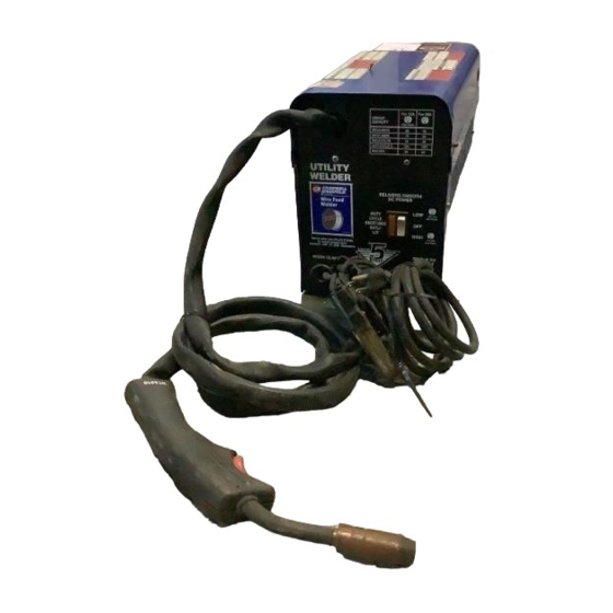
Figure 1 - Welder Components and Controls
wire feed cover to find handle,
workclamp, etc. When unpacking,
inspect carefully for any damage that
may have occurred during transit. Make
sure any loose fittings and screws, etc.
are tightened before putting unit into
service.
Circuit Requirements
This equipment
CAUTION
!
requires a dedicated
115 volt circuit. Refer to the following
chart for the correct circuit breaker or fuse
rating. Do not run other appliances, lights,
or tools on this circuit while operating this
equipment. Extension cords are not
recommended. Blown fuses and tripped
circuit breakers can result from failure to
comply with this recommendation.
Heat
Circuit Breaker or
Selector
Slow Blow Fuse
Low
15 amp
High
20 amp
See page 6 for supply cable
replacement instructions.
For parts, product & service information
visit www.chpower.com
3
4
4
e r
r
e ld
ld e
W e
W
Fi l
Fi l
e d
e d
e Fe
e Fe
e n
e n
W ir
W ir
e n te
e n te
n u o
n u o
o n ti
o n ti
r A
r A
lim
lim
d e u
d e u
e C
re C
m b
m b
r
S o u
S o u
A la
A la
co n
co n
d a r
d a r
S o la
S o la
2
Components and Controls
WF1800/WF1900
1. Work Clamp - connect to work piece.
2. Wire Feed Gun with .035" tip.
3. Power Cord - plug into 115 volt
outlet.
4. Low/Off/High Switch - set according
to metal thickness. Automatically
controls wire speed. Lights if
thermostat has automatically shut
unit off.
WF2000
1. Work Clamp - connect to work piece.
2. Wire Feed Gun with .035" tip.
3. Power Cord - plug into 115 volt
outlet.
4. On/Off Switch - lights if thermostat
has automatically shut unit off.
5. Infinite Wire Speed Control - turn
clockwise to increase wire speed and
counterclockwise to decrease wire
speed.
6. Heat Selector - Selects welding
power. Two selections are possible;
low and high.
Need
Assistance?
Call Us First!
1-800-746-5641
WF2000
6
5
1
3
IN199006AV 3/02
Advertisement
Table of Contents

Related Manuals for Campbell Hausfeld WF1800


Summary of Contents for Campbell Hausfeld WF1800
-
Page 1: Components And Controls
Assistance? Arc Welder Call Us First! 1-800-746-5641 BUILT TO LAST Description The Campbell Hausfeld WF1800, WF1900 WF1800 and WF2000 are 70 amp, single phase WF2000 115 volt input, wire feed arc welding U TI LI TY U TI LI TY... -
Page 2: General Safety
Operating Instructions and Parts Manual General Safety all precautions described in this manual properly supported and grounded to reduce the possibility of injury to eyes prior to beginning any electric arc and skin. Danger means a welding operation. DANGER G All persons operating this equipment hazard that will G Coiled welding cable should be cause death or serious injury if the... - Page 3 Models WF1800, WF1900 and WF2000 ADDITIONAL SAFETY STANDARDS significantly degrade the General Safety performance of the welder. ANSI Standard Z49.1 from American (Continued) Welding Society, 550 N.W. Le June Rd. Miami, FL 33126 Assembly - WARNING Safety and Health Standards welding closed cylinders WF1800/WF1900 OSHA 29 CFR 1910, from Superintendent...
- Page 4 Operating Instructions and Parts Manual Assembly - WF1800/ Flux Core Wire Installation Nozzle Torch Contact Tip WF1900 (Continued) Welding power Diffuser WARNING may be applied to Any mismatch could cause the wire to the output terminals, feed roll, work slip, bind or weld poorly. clamp, gun cable connection and welding wire even when the the gun switch is not Contact Tip Markings...
- Page 5 Models WF1800, WF1900 and WF2000 Assembly - WF2000 WF2000 adjustment controls the fit of the helmet when it is lowered, and can be (Continued) easily repositioned if necessary. 1. Cut retainer stiffeners and detachable handle away from shield. the spool on the end closest to the 4.
-
Page 6: Welding Guidelines
Operating Instructions and Parts Manual Maintenance Operation (Continued) 2. Use compressed air to blow all dust and lint from the ventilation Disconnect power openings. WARNING Metal Heat supply and turn 3. Clean the wire groove on the drive Thickness Setting machine off before inspecting or roll. - Page 7 Models WF1800, WF1900 and WF2000 Welding Guidelines (Continued) WIRE TYPE AND SIZE Travel angle is the angle in the line of bead which prevents contaminants in welding and may vary from 5º to 45º the air from reacting with the molten The correct choice of wire type involves a from the vertical, depending on welding metal.
- Page 8 Operating Instructions and Parts Manual Welding Guidelines (Continued) PUSH VS PULL TECHNIQUE The type and thickness of the work piece dictate which way to point the gun nozzle. For thin materials (18 gauge and up), the nozzle should point out in front PULL of the weld puddle and push the puddle across the workpiece.
-
Page 9: Weld Appearance And Wiring
Models WF1800, WF1900 and WF2000 Base metal Normal heat, wire speed, Travel speed too fast travel speed Heat too low Travel speed too low Wire speed too slow Heat too high Figure 17 - Weld Appearance Wire speed too fast TO WORK CLAMP TO TORCH S3 NC... - Page 10 Operating Instructions and Parts Manual For Information About This Product Call 1-800-746-5641 Troubleshooting Chart - Welder Symptom Possible Cause(s) Corrective Action 1. Allow welder to cool until ON/OFF Switch lamp goes out 1. Duty cycle exceeded No output 2. Be sure all connections are secure, and attaching surface is 2.
- Page 11 Models WF1800 & WF1900 Inside U T IL IT Y W E L D E ld e e ld DE LI VE DE LI VE W ir W ire Fe RS SM RS SM e e d e e d e Fe ed O O TH O O TH...
- Page 12 Model WF2000 Operating Instructions and Parts Manual For Information About This Product Call 1-800-746-5641 Inside 10, 11 Figure 21 - Model WF2000 Replacement Parts Ref. Ref. Description Part Number Description Part Number Torch assembly and hose WC600900AJ Spool adapter WC500200AV Torch body, front and back WC600201AV Spool spring...
- Page 13 8. Responsibilities of purchaser under this warranty: A. Deliver or ship the Campbell Hausfeld product or component to Campbell Hausfeld. Freight costs, if any, must be borne by the purchaser. B. Use reasonable care in the operation and maintenance of the products as described in the owner’s manual(s).
- Page 14 6. Sélecteur de Chaleur - Pour choisir la instructions de remplacement du cordon d’alimentation du fil pour trouver la puissance de soudage. Deux sélections poignée, la pince, etc. Lors du d’alimentation. sont possibles; réglage bas et haut. IN199006AV 3/02 © 2002 Campbell Hausfeld/Scott Fetzer 14 Fr...
- Page 15 Modèles WF1800, WF1900 et WF2000 G S’assurer que l’objet sur lequel vous chaleur et rayons ultraviolets (UV). Cette Généralités Sur la travaillez est bien fixé et mis à la lumière intense et rayons UV peuvent Sécurité terre correctement avant de causer des blessures aux yeux et à...
- Page 16 Instructions D’Utilisation et Manuel de Pièces G Choisir un endroit pour le soudeur Généralités Sur la d’autres réactions inconnues qui fournit au moins douze pouces concernant la santé. Sécurité (Suite) (30,48 cm) d’espace pour la Toujours AVERTISSEMENT ventilation en avant et en arrière du G Prendre précaution pour s’assurer laisser modèle.
- Page 17 Modèles WF1800 et WF2000 glisser le fil nu sous le bloc de la Montage - fil se démêle. S’assurer que le bout WF1800/WF1900 pince. Serrer le boulon hexagonal et du fil soit droit et sans ébarbures. (Suite) s’assurer que le fil nu soit bien serré 5.
- Page 18 Instructions D’Utilisation et Manuel de Pièces la lentille ombragée des étincelles et Montage - WF2000 (Suite) Lentille des projections. Fixez les deux d’une montre. Le bouton, ressort, et lentilles en encliquetant le dispositif bague d’espacement de la bobine de retenue des lentilles en place. Dispositif de peuvent êtres enlevés.
- Page 19 Modèles WF1800 et WF2000 nettoyer le rouleau d’entraînement. 11. Une fois fini avec le soudage, mettre Fonctionnement (Suite) Remplacer si usé ou endommagé. le soudeur hors circuit (off) et sûr et qu’il n’est pas pollué par la l’entreposer correctement. Pièces Consommables et peinture, le vernis, la corrosion, ou Pièces qui Peuvent S’User autres matériaux non-métalliques.
- Page 20 Instructions D’Utilisation et Manuel de Pièces Directives De Soudage (Suite) TYPE ET TAILLE DE FILS variable de 5º à 45º du vertical selon les appelée scorie couvre le cordon de conditions de soudage. soudure et empêche la réaction du Le choix correct du fil comprend une métal fondu avec les polluants dans l’air.
- Page 21 Modèles WF1800 et WF2000 Directives De Soudage (Suite) TECHNIQUE POUSSER-TIRER Le type et l’épaisseur de l’objet de travail détermine le placement de la buse du pistolet. Pour les matériaux minces (calibre 18 et plus), pointer la buse en avant de la flaque et pousser la flaque à...
- Page 22 Instructions D’Utilisation et Manuel de Pièces REMARQUE: La largeur (W) du cordon de soudeur devrait être approximativement deux fois le Métal Commun diamètre de la baguette d’électrode utilisée. Chaleur, vitesse de fil et vitesse de déplacement ordinaires Vitesse de déplacement trop rapide Vitesse de déplacement trop lente Chaleur trop basse Chaleur trop haute...
- Page 23 Modèles WF1800 et WF2000 Pour Des Informations Concernant Ce Produit, Appeler 1-800-746-5641 Guide De Dépannage - Soudeur Symptôme Cause(s) Possible (s) Mesures Correctives 1. Permettre que le soudeur se refroidit jusqu’à ce que la lampe de 1. Facteur d’utilisation dépassé Manque de puissance l’indicateur ON/OFF s’éteint 2.
- Page 24 Instructions D’Utilisation et Manuel de Pièces Modèles WF1800 Pour Des Informations Concernant Ce Produit, Appeler 1-800-746-5641 Inside A L’Intérieur U T IL IT Y W E L D E ld e e ld DE LIV ER DE LIV ER W ir W ire Fe S SM O S SM O...
- Page 25 Instructions D’Utilisation et Manuel de Pièces Modèle WF2000 Pour Des Informations Concernant Ce Produit, Appeler 1-800-746-5641 Inside A L’Intérieur 10, 11 Figure 21 - Modèle WF2000--Pièces de Rechange No de Numéro No de Numéro Réf Description de Pièce Qté Réf Description de Pièce Qté...
- Page 26 8. Responsibilités De L’Acheteur Aux Termes De Cette Garantie: A. Livraison ou expédition du produit ou pièce Campbell Hausfeld à Campbell Hausfeld. Taux de frais , si applicable, sont la responsabilité de l’acheteur.
- Page 27 Arco Con Alambre Continuo BUILT TO LAST Descripción Los modelos WF1800 y WF2000 de WF1800 Campbell Hausfeld son soldadoras con arcos eléctricos, monofásicas de 70 amp, WF2000 U TI LI TY U TI LI TY 115 volt input. El modelo WF2000 está...
- Page 28 Manual de Instruccones y Lista de Repuestos la use en áreas húmedas, mojadas, a mientras se esté usando el equipo Seguridad General la intemperie o que no estén bien deben usar vestimenta de ventiladas. protección para soldadores PELIGRO Esto le incluyendo: casco para soldadores o G Antes de comenzar a soldar indica una...
- Page 29 Modelos WF1800, WF1900 y WF2000 Seguridad General CGA Pamphlet P-1, CSA Standard W117.2, NFPA Standard 51B ANSI (Continuación) Standard Z87.1. Aquellas personas que residan en países latinoamericanos ADVERTENCIA deben consultar los códigos y regula- ciones que se apliquen en sus respec- !Al soldar con arcos eléctricos tivos países.
- Page 30 Manual de Instruccones y Lista de Repuestos Ensamblaje - WF1800/WF1900 sentido de las manillas del reloj y Nota: Antes de instalar el alambre de empújela.(Vea la Figura 5). Corte el soldar, asegúrese de que el diámetro de (Continuación) alambre aproximadamente 6,4mm éste coincida con la ranura en la bobina 1.
- Page 31 Modelos WF1800, WF1900 y WF2000 Ensamblaje - WF2000 4. Para conectar el mango, coloque la del casco (y del brazo de ajuste en el máscara sobre una superficie plana y lado derecho) dentro de la tuerca (Continuación) presione el mango hasta que calce tensora como se muestra.
- Page 32 Manual de Instruccones y Lista de Repuestos mecanismo de alimentación, saque Funcionamiento Mantenimiento los tornillos de la bobina. Use un Continuación) cepillo pequeño de alambres para ADVERTENCIA limpiar la bobina. Reemplácela si está desgastada o dañada. Grosor Nivel de la Desconecte y apa-gue la soldadora del Metal Corriente...
- Page 33 Modelos WF1800, WF1900 y WF2000 Instrucciones para soldar (Continuación) TIPO Y TAMAÑO DEL ALAMBRE soldadura. Antes de comenzar a soldar Una vez que haya terminado de soldar, haga una prueba en un pedazo de metal espere a que las piezas soldadas se La selección del tipo correcto de alambre del mismo tipo y grosor que la pieza de enfríen.
- Page 34 Manual de Instruccones y Lista de Repuestos Instrucciones para soldar (Continuación) METODO USADO PARA SOLDAR Según el tipo de material y el grosor de la pieza de trabajo deberá usar un método de desplazamiento de la pistola soldadora. Para soldar materiales delgados (de calibre 18 ó...
- Page 35 Modelos WF1800, WF1900 y WF2000 Nota: El ancho (A) del reborde debe ser aproximadamente el doble del diámetro de la varilla de electrodo que se use. Metal Básico Corriente, velocidad de alimentación y velocidad de desplazamiento normales Velocidad muy rápida Corriente muy baja Velocidad muy lenta Corriente muy alta...
- Page 36 Manual de Instruccones y Lista de Repuestos Guía de diagnóstico de averías - Soldadora Problema Posible(s) Causa(s) Acción a tomar No funciona 1. Excedio el ciclo de trabajo 1. Deje que la soldadora se enfrie hasta que la luz del interruptor ON/OFF se apague 2.
- Page 37 Modelos WF1800 y WF1900 Inside Adentro U T IL IT Y W E L D E ld e e ld DE LI VE DE LI VE W ir W ire Fe RS SM RS SM e e d e e d e Fe ed O O TH O O TH...
- Page 38 Manual de Instruccones y Lista de Repuestos Modelo WF2000 Adentro Inside 10, 11 Figura 21 - Repuestos - WF2000 No. de No. de Ref. Descripción Número Ctd. Ref. Descripción Número Ctd. Ensamblaje del soplete y manguera WC600900AJ 1 Adaptador del carrete WC500200AV 1 Soplete, parte frontal y posterior WC600201AV 1...
- Page 39 8. Responsibilidades del Comprador bajo esta Garantía: A. Entregar o enviar el producto o componente a Campbell Hausfeld. Los gastos de flete, si los hubiere, deben ser pagados por el comprador.
- Page 40 Operating Instructions and Parts Manual Models WF1800 and WF2000 Modèles WF1800 et WF2000 Manual de Instruccones y Lista de Repuestos Modelos WF1800 y WF2000 Instructions D’Utilisation et Manuel de Pièces Service Record État de Service Registro de servicio Wire Feed Arc Welder Soudeur À...