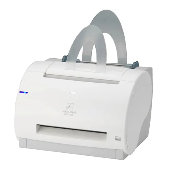
Canon LBP-1120 Service Manual
Laser beam printer
Hide thumbs
Also See for LBP-1120:
- Specifications (4 pages) ,
- User manual (194 pages) ,
- Getting started manual (16 pages)

Related Manuals for Canon LBP-1120


Summary of Contents for Canon LBP-1120
- Page 1 LBP-1120 SERVICE MANUAL REVISION 0 FY8-13HT-000 JULY. 2002 LBP-1120 COPYRIGHT © 2002 CANON INC. CANON REV.0 MAY. 2002 PRINTED IN JAPAN (IMPRIME AU JAPON)
- Page 2 This manual may contain technical inaccuracies or typographical errors due to improvements or changes in prod- ucts. When changes occur in applicable products or in the contents of this manual, Canon will release technical information as the need arises. In the event of major changes in the contents of this manual over a long or short period, Canon will issue a new edition of this manual.
-
Page 3: Chapter 1 Product Information
PREFACE PREFACE This Service Manual contains basic information required for after-sales service of the laser beam printer LBP-1120 (hereinafter referred to as the “printer”). This information is vital to the service technician in maintaining the high print quality and performance of the printer. This manual consists of the following chapters: Chapter 1: Product information... - Page 4 PREFACE P - 2...
-
Page 5: Table Of Contents
BY THE CUSTOMER ...... 1-10 C. Ozone Safety ......1-4 VII. OPERATION ........1-11 PARTS OF THE PRINTER ....1-5 A. Canon Advanced Printing A. External View ......1-5 Technology (CAPT) ....1-11 CHAPTER 2 OPERATION AND TIMING BASIC OPERATION ......2-1 III. - Page 6 PREFACE MOTOR/SOLENOID ......3-15 VII. PCBS ..........3-17 A. Arrangement of the Components 3-15 A. Arrangement of the Components 3-17 B. Main Motor ......... 3-16 B. Interface Controller PCB .... 3-18 C. Pick-up Solenoid ......3-16 C. Engine Controller PCB ....3-18 D.
- Page 7 CHAPTER 1 PRODUCT INFORMATION FEATURES ........... 1-1 INSTALLATION ........1-7 SPECIFICATIONS ........ 1-2 MAINTENANCE AND CHECKS III. SAFETY INFORMATION ....1-4 BY THE CUSTOMER ......1-10 PARTS OF THE PRINTER ....1-5 VII. OPERATION ......... 1-11...
-
Page 8: Features
10 pages per minute (A4) and high resolution of 600 dpi. 2. Employment of Canon Advanced Printing Technology With Canon Advanced Printing Technology, data can be processed within a host computer. This frees the printer from the PDL conversion and image processing, increasing the speed performance and reducing the cost. -
Page 9: Specifications
76.2 mm(W) x 127 mm(L) ~ 216 mm(W) x 356 mm(L) sized paper (64 g/m to 105 Canon recommended paper) and above mentioned paper Multi-purpose tray 76.2 mm(W) x 127 mm(L) ~ 216 mm(W) x 356 mm(L) sized paper (64 g/m... - Page 10 6. To print duplex manually, uncurl the face-up delivered paper and set it in the multi-purpose tray. 7. Without the delivery guide and the paper pickup sub tray. 2. Interface controller 1) Printing System Canon Advanced Printing Technology 2) ROM capacity 8 KB 3) RAM capacity...
-
Page 11: Safety Information
CHAPTER 1 III. SAFETY INFORMATION A. Handling the Laser/Scanner Unit An invisible laser beam is emitted within the laser/scanner unit. The laser beam can cause eye damage if exposed, so be sure not to disassemble the laser/scanner unit. It is not necessary to adjust the laser/scanner unit in this printer in the filed. -
Page 12: Parts Of The Printer
CHAPTER 1 IV. PARTS OF THE PRINTER A. External View [10] [13] [12] [11] [1] : Multi-purpose tray [2] : Paper width guide [3] : Manual feed slot [4] : Delivery switching lever [5] : Face-up delivery port [6] : Cartridge cover unit [7] : Face-down delivery tray [8] : Display unit [9] : Delivery guide... -
Page 13: B. Cross Section
CHAPTER 1 B. Cross Section [13] [12] [11] [10] [1] : Face-down delivery roller [2] : Fixing film unit [3] : EP-22 cartridge [4] : Primary charging roller [5] : Laser/scanner unit [6] : Pick-up roller [7] : Separation pad [8] : Feed roller [9] : Developing cylinder [10] : Transfer charging roller... -
Page 14: V. Installation
CHAPTER 1 V. INSTALLATION A. Precautions This product has been carefully adjusted and strictly inspected before packing and shipping. To make the operation as intended, it is important to install it correctly. Service engineers must understand the performance of the printer sufficiently, install it in the appropriate environment with proper procedures, and operate the necessary checks. -
Page 15: Cartridge
CHAPTER 1 B. Storage and Handling of EP-22 Cartridge As time passes, the natural environment will change the cartridge, whether sealed or installed in the printer, or regardless of the number of prints. The progression of this natural change depends largely on the storage and installation environment, therefore, take special care on storage and handling the cartridge. - Page 16 CHAPTER 1 c. Notes on Handling of Cartridge 1) Before installing a new EP-22 cartridge in the printer, hold the cartridge at both sides as shown below, and gently slop it at about 45 ° right-up and left-up 5 or 6 times to distribute toner evenly. Do not rock the cartridge in any other way, as the toner may leak from the developing unit or cleaner unit.
-
Page 17: By The Customer
CHAPTER 1 VI. MAINTENANCE AND CHECKS BY THE CUSTOMER The table below lists the maintenance points that should be performed by the customer to maintain the printer at optimum level. Table 1-6-1 Item Customer maintenance Cartridge Shake or replace the cartridge as necessary. External Cover Clean the external cover as necessary. -
Page 18: Operation
VII. OPERATION A. Canon Advanced Printing Technology (CAPT) Canon Advanced Printing Technology (hereafter referred to as CAPT) reduces the processing time and simplifies the operations for printing in the Microsoft Windows environment. The easy operations and speedy printing are supported by the following features of CAPT: •... -
Page 19: Operation And Timing
CHAPTER 2 OPERATION AND TIMING This chapter describes the printer functions, the relationships between mechanisms and circuits, and the timing of operations. Mechanical linkages are indicated by black and white lines ( ), the flow of control signals by solid arrows ( ), and the flow of groups of signals by outline arrows ( There is a microcomputer in this printer. -
Page 20: Basic Operation
CHAPTER 2 I. BASIC OPERATION A. Functions Printer functions can be divided into five groups: video control system, engine control system, image formation system, laser/scanner system, and paper pickup/feed system. VIDEO CONTROL SYSTEM Interface controller Display To external device (host computer,etc.) LASER/SCANNER SYSTEM ENGINE CONTROL Scanning mirror... -
Page 21: Basic Operation Sequence
CHAPTER 2 B. Basic Operation Sequence The operation sequence of this printer is controlled by the microcomputer on the engine controller PCB. The table describes the purpose of each period from the time the printer is turned ON until the main motor stops rotating after the completion of printing. -
Page 22: Power-On Sequence
CHAPTER 2 C. Power-ON Sequence The following explains the sequence from power-ON until the printer enters the STANDBY mode. 1) Power-ON. 2) CPU initialization. 3) The video interface communication start. After 0.5 seconds from the time the status command signal (/SC) turns “H”, the video interface becomes ready to communicate. -
Page 23: Engine Control System
CHAPTER 2 II. ENGINE CONTROL SYSTEM A. Engine Controller PCB 1. Outline The operation sequence of the printer is controlled by the CPU on the engine controller PCB. When the printer is turned ON and enters the STANDBY mode, the CPU outputs signals to drive loads, such as the laser diode, motors, and solenoids, based on the pickup command and image data input from the interface controller. - Page 24 CHAPTER 2 2. Operations a. CPU (IC201) This printer contains an 8-bit single-chip microcomputer for its CPU. This CPU is a single-chip CPU with a built-in ROM and RAM. It performs the controls for the following items based on the control program stored in the ROM. 1) Printer sequence.
- Page 25 CHAPTER 2 3. Engine Controller Input and Output Laser/scanner unit Engine controller PCB +24V J802-1 J208-4 M801 "L" decelerates the scanner motor . /DEC Scanner /ACC "L" accelerates the scanner motor . motor Scanner motor driver circuit J801-8 J208-5 +3.3V Laser diode Video signals /VDO...
- Page 26 CHAPTER 2 Engine controller PCB SW101 J101-1 AC-H AC power power input input AC-N Thermal Fixing film unit fuse J703M-1 J703F-2 J102-1 NEUTRAL FU701 H701 Fixing heater Thermistor J703L-1 J703D-2 J206-1 FSRTH Fixing heater temperature Fixing heater detection signal temperature TH701 detection EP-22 Cartridge...
-
Page 27: B. Fixing Control Circuit
CHAPTER 2 B. Fixing Control Circuit 1. Fixing Temperature Control The fixing film unit of the printer contains a plate-shaped fixing heater to heat up the fixing film. The fixing heater temperature is detected by the thermistor (TH701) on the fixing heater. When the temperature rises, the resistance of TH701 drops and the voltage of the FIXING HEATER TEMPERATURE DETECTION signal (FSRTH) decreases. -
Page 28: Protection Function
CHAPTER 2 3. Protection function The printer contains the following three protective functions in order to prevent excursion of the fixing heater. ◆ The CPU monitors the voltage of TH701. When detecting an abnormality, the CPU assesses a fixing heater failure and sets the FIXING HEATER DRIVE signal (FSRD) to “L”... - Page 29 CHAPTER 2 C. High-Voltage Power Supply Circuit 1. Outline Engine controller PCB IC201 Primary high voltage circuit Primary charging roller DC voltage J305 generation PRDCC Photosensitive drum circuit J304 IC302 Combined CRGSNS Developing cylinder AC voltage J303 generation circuit Power operational amplifier Transfer charging roller Developing bias circuit...
- Page 30 CHAPTER 2 2. Operation a. Primary Charging Roller Voltage Generation When the pickup command is sent from the interface controller, the INITIAL ROTATION period (INTR) starts, and the PRIMARY HIGH VOLTAGE (AC) DRIVE signal (PRACC) is input to the primary high-voltage circuit via the power operational amplifier.
- Page 31 CHAPTER 2 D. Low-Voltage Power Supply Circuit 1. Outline The AC voltage input from the inlet is converted into the DC voltage in the rectification circuit, transformer, and power supply circuits. Then, the DC voltage is supplied to the printer as +24VDC, +5VDC, and +3.3VDC. When the cartridge door is opened, the door switch (SW301) is turned OFF.
-
Page 32: Protective Function
CHAPTER 2 2. Protective Function The power supply circuits of the +24VDC and +5VDC contain overcurrent and overvoltage protective functions. These protective functions automatically shut off the output voltage in order to protect the circuits, when an overcurrent or overvoltage condition occurs due to the troubles such as a short circuit on the loads. When the protective functions are activated and no DC voltage is output from the power supply circuits, it is necessary to turn OFF the power, rectify the troubles on the loads, and then turn ON the power again. -
Page 33: E. Video Interface
CHAPTER 2 E. Video Interface 1. Outline Unlike the conventional video interface, which uses an exclusive line for each of the signals exchanged between the interface controller and engine controller, this printer uses command status. This section describes the types of the interface signals used between the engine controller and interface controller, and gives information on the sequence of the printer operations. - Page 34 CHAPTER 2 2. Operation When the power is switched ON, the printer enters the WAIT period. When the printer exits the WAIT period and is ready to operate, the engine controller sends ready status to the interface controller to notify that it is ready to print. On receiving the ready status, the interface controller sends a pickup command to the engine controller.
- Page 35 CHAPTER 2 3. Cleaning Page The printer executes a cleaning page sequence by the command sent from the interface controller. The cleaning page cleans the pressure roller. Receiving a cleaning page execution command from the interface controller, the engine controller conducts the paper pickup operation.
-
Page 36: Laser/Scanner System
CHAPTER 2 III. LASER/SCANNER SYSTEM A. Outline The printer contains a laser driver (IC801) on its laser driver PCB. The microcomputer (CPU : IC201) on the engine controller sends the LASER CONTROL signals (CNT0, CNT1) to the IC801. Meanwhile, the interface controller sends the VIDEO signals (/VDO, VDO) to the IC801 through the engine controller. -
Page 37: Laser Control Circuit
CHAPTER 2 B. Laser Control Circuit 1. Outline Engine controller PCB Laser driver PCB IC201 /BDI J208F-11 J801F-2 BD sensor +3.3V J208F-12 J801F-1 J208F-5 J801F-8 IC801 J208F-6 J801F-7 Comparator (photodiode) CNT0 J208F-9 J801F-3 CNT1 (laserdiode) Sample J208F-9 J801F-4 hold circuit Logic circuit C803... -
Page 38: Horizontal Synchronization Control
CHAPTER 2 2. Laser Diode Automatic Power Control The laser diode automatic power control (APC) is performed by the IC801. The APC makes the laser diode emit laser beams at a constant intensity. It is performed prior to the image formation (Initial APC) and during the between-line (between line APC). - Page 39 CHAPTER 2 Unmasking area 1 mm 1 mm Figure 2-3-3 Notes: 1. The shaded area indicates the area where the laser beam can write. 2. T1 is the range between 1mm from the right side and 1mm from the left side of the Letter size. It is not dependent on the specified paper size.
-
Page 40: Scanner System
CHAPTER 2 C. Scanner System The scanner motor control circuit is shown below. Engine controller PCB Laser/scanner unit +3.3V /BDI J801F-2 J208F-11 BD sensor +24VA +24VA J208-4 J802-1 Scanner driver IC J208-3 /ACC /ACC J802-2 Frequency Integration Drive comparator circuit circuit J208-2 J802-3... - Page 41 CHAPTER 2 The CPU detects the following failures and error by monitoring /BDI signal sent from the BD sensor, and reports it to the interface controller: 1) Scanner Failure When the /BDI cycle does not reach the specified value within 3.5 seconds after the scanner motor was forcibly accelerated at its start-up.
-
Page 42: Image Formation System
CHAPTER 2 IV. IMAGE FORMATION SYSTEM A. Outline The image formation system is the central hub of the printer, and consists of the photosensitive drum, developing unit, charging roller, etc. When receiving a pickup command from the interface controller, the engine controller drives the main motor to rotate the photosensitive drum, developing cylinder, primary charging roller, and transfer charging roller. -
Page 43: Print Process
CHAPTER 2 B. Print Process The major portion of the image formation system is contained in a cartridge as shown in Figure 2-4-2. Laser beam Primary charging roller Cartridge Blade Cleaning blade Photosensitive drum Developing cylinder Static charge eliminator Transfer charging roller Figure 2-4-2 The cartridge used by the printer contains a two-layered seamless as shown in Figure 2-4-3. -
Page 44: Electrostatic Latent Image Formation Stage
CHAPTER 2 Electrostatic latent image formati on stage Flow of paper 2.Scanning exposure Direction of drum rotation 1.Primary charging Developing stage 3.Developing Drum cleaning stage 7.Drum cleaning Fixing stage Paper delivery 5.Separation 4.Transfer 6.Fixing Transfer stage Figure 2-4-4 1. Electrostatic Latent Image Formation Stage This stage consists of two steps which form an electrostatic latent image on the photosensitive drum. - Page 45 CHAPTER 2 Step 1: Primary charging Primary charging roller AC bias Photosensitive drum DC bias Figure 2-4-6 For preparation of latent image formation, a uniform negative potential is applied to the photosensitive drum surface. Primary charging of this printer is performed by the method that directly charges the photosensitive drum. The primary charging roller consists of semiconductive rubber.
- Page 46 CHAPTER 2 2. Developing Stage Toner is applied to the electrostatic latent image on photosensitive drum surface to form a visible image. This printer performs the toner projection development with a single-component toner. Step 3: Development Stirrer Blade Photosensitive drum AC bias Developing cylinder DC bias...
- Page 47 CHAPTER 2 An AC bias is applied to the developing cylinder to help project the toner particles to the drum surface and improve the contrast of the printed image. The center voltage of the AC bias (1460 Vp-p) varies with the developing DC bias. This printer changes the developing DC bias value according to the IMAGE DENSITY DATA signal sent from the interface controller.
-
Page 48: Fixing Stage
CHAPTER 2 4. Fixing Stage As the toner image transferred onto the paper in the transfer stage is held to the paper only by the static electricity, even a light touch will smear the image. The toner particles are fused to the paper to make a permanent image by applying pressure and heat to the paper and toner. - Page 49 CHAPTER 2 5. Photosensitive Drum Cleaning Stage At the photosensitive drum cleaning stage, the photosensitive drum surface is cleaned in preparation for the next print operation. Step 7: Photosensitive Drum Cleaning Cleaner container Cleaning blade Photosensitive drum Sweeper strip Figure 2-4-13 Prior to the next printing, the residual toner on the drum surface is scraped away by the cleaning blade to clean the drum surface.
-
Page 50: Pickup/Feed System
CHAPTER 2 V. PICKUP/FEED SYSTEM A. Outline The printer is equipped with two pickup sources, the multi-purpose tray and manual feed slot. Whether or not the multi-purpose tray and the manual feed slot are loaded with paper is detected by the paper-out sensor (PS003). - Page 51 CHAPTER 2 After the specified period of time from the time the paper reaches the paper top sensor (PS002), the engine controller sends the /BD signal to the interface controller. The interface controller sends the VIDEO signal to the engine controller based on the /BD signal.
-
Page 52: Jam Detection
CHAPTER 2 B. Jam Detection The following paper sensors are installed to detect whether paper is present and whether the paper is fed correctly: • Paper top sensor (PS002) • Paper delivery sensor (PS201) The CPU determines a paper jam by checking for the presence of paper in the sensor at the timing stored in the CPU. If the CPU determines that a jam has occurred, it stops the print operation and notifies the jam to the interface controller. -
Page 53: Video Control System
CHAPTER 2 VI. VIDEO CONTROL SYSTEM A. Interface Controller PCB 1. Outline The interface controller receives print information from an external device such as a host computer through an interface cable. Print information is divided into two types: CAPT commands used for the printer status and information on the printer, and dot data that is converted from the resource-typed print data by the host computer. - Page 54 CHAPTER 2 Figure 2-6-1 2 - 35...
- Page 55 CHAPTER 3 THE MECHANICAL SYSTEM PREFACE ..........3-1 SWITCHES,SENSORS, AND LEDS ..3-13 EXTERNALS ........3-2 MOTOR/SOLENOID ......3-15 III. MAIN UNITS ......... 3-5 VII. PCBS ............ 3-17 MAJOR COMPONENTS ...... 3-9...
-
Page 56: I. Preface
CHAPTER 3 I. PREFACE This chapter describes the disassembly and reassembly procedures of the printer. The service technician is to identify the factor of malfunction according to the “Chapter 4 Troubleshooting” and to replace the defective part(s) following the disassembly procedure of each part. Note the following precautions when working on the printer. -
Page 57: Ii. Externals
CHAPTER 3 B. External Covers II. EXTERNALS 1. Rear Cover 1) Remove the screw. A. Arrangement of the Components 2) Locate the claw under the area indicated by an arrow. Open the bottom of the left/right side of the rear cover, and slide it to the front; free the claw, and lift the rear cover to detach. -
Page 58: Left Cover
CHAPTER 3 3. Left Cover 3) Remove the 2 screws, and free the 2 claws; then, 1) Remove the screw detach the upper cover. 2) Open the cover of the cartridge assembly. 3) Remove the screw and, free the law under the area indicated by an arrow, and free the hook;... - Page 59 CHAPTER 3 6. Pickup Tray 5) Slide the shaft, and detach the cartridge cover. 1) Remove the rear cover. 2) Slide up the pickup tray to detach. [1] Shaft [2] Cartridge cover Figure 3-2-8 [1] Pickup tray Figure 3-2-9 3 - 4...
-
Page 60: Iii. Main Units
CHAPTER 3 III. MAIN UNITS B. Drive Assembly A. Laser/scanner Unit 1) Remove the rear cover and the left/right cover. 2) Remove the 2 screws and 2 screws equipped with 1) Remove the rear cover, left/right cover, and upper a washer. Slide out the drive assembly slightly, cover. - Page 61 CHAPTER 3 C. Feed Assembly 4) Remove the 2 screws, and disconnect the 2 connectors; then, remove the feed assembly. 1) Remove the engine controller assembly. (See VII- C of Chapter 3.) 2) Free the 2 claws, and remove the 2 gears and the screw.
-
Page 62: E. Fixing Film Unit
CHAPTER 3 D. Delivery Assembly E. Fixing Film Unit 1) Open the cartridge cover. 1) Remove the rear cover and the left/right cover. 2) Remove the boss, and remove the face-down 2) Remove the delivery assembly. delivery roller bushing; then, slide the face-down 3) With the pressure release lever shifted up, push delivery roller to the right to detach. - Page 63 CHAPTER 3 5) Disconnect the connector, and free the harness from the harness guide. 6) Remove the fixing film unit. [1] Connector [2] Harness guide [3] Harness [4] Fixing film unit Figure 3-3-10 3 - 8...
-
Page 64: Pickup Roller
CHAPTER 3 IV. MAJOR COMPONENTS A. Arrangements of the Components Figure 3-4-1 [1] Pickup roller [2] Separation pad [3] Transfer charging roller [4] Pressure roller 3 - 9... -
Page 65: Separation Pad
CHAPTER 3 B. Pickup Roller C. Separation Pad 1) Open the cartridge cover. 1) Remove the drive assembly. (See III-B of Chapter 2) Pull the bottom of the pickup roller to the front to detach. 2) Remove the pickup tray. 3) Remove the claw, and slide the pickup roller shaft to the left. - Page 66 CHAPTER 3 4) Peel the Warning label (laser) halfway from the 7) Move the holding unit in the direction of the arrow Laser/scanner unit. to detach the separation pad. 5) Remove the 2 screws and the screw equipped with a washer; then, disconnect the 2 connectors, and detach the scanner base unit.
-
Page 67: Transfer Charging Roller
CHAPTER 3 D. Transfer Charging Roller E. Pressure Roller 1) Open the cartridge cover. 1) Remove the drive assembly. 2) Pick the 2 claws of the bushing found on the left, (See III-B of Chapter 3.) and lift them; while doing so, slide the transfer 2) Remove the fixing film unit. -
Page 68: Switches,Sensors, And Leds
CHAPTER 3 V. SWITCHES, SENSORS, AND LEDS A. Arrangement of the Components LED601 PS003 SW101 PS002 SW201 PS201 SW301 Figure 3-5-1 SW101: power switch (engine controller PCB) SW201: test print switch (engine controller PCB) SW301: door open detection switch (engine controller PCB) PS002: paper top sensor PS003: paper-out sensor PS201: paper delivery sensor (engine controller PCB) -
Page 69: Paper Top Sensor/Paper-Out Sensor
CHAPTER 3 B. Paper Top Sensor/Paper-Out Sensor 1) Remove the feed assembly. (See III-C of Chapter 3.) 2) Remove the paper top sensor/paper-out sensor. [1] Paper top sensor [2] Paper-out sensor Figure 3-5-2 C. Power Switch, Test Print Switch, Door Open Detection Switch, Paper Delivery Sensor 1) Remove the engine controller PCB. - Page 70 CHAPTER 3 VI. MOTORS AND SOLENOIDS A. Arrangement of the Components SL001 M001 Figure 3-6-1 M001: main motor SL001: pick-up motor 3 - 15...
-
Page 71: Main Motor
CHAPTER 3 B. Main Motor C. Pick-up Solenoid 1) Remove the drive assembly. 1) Remove the drive assembly. (See III-B of Chapter 3.) (See III-B of Chapter 3.) 2) Remove the 2 screws, and detach the main motor. 2) Disconnect the connector J204 from the engine controller PCB;... -
Page 72: Vii. Pcbs
CHAPTER 3 VII. PCBS A. Arrangement of the Components Figure 3-7-1 [1] Interface controller PCB [2] Engine controller PCB [3] Display PCB 3 - 17... -
Page 73: B. Interface Controller Pcb
CHAPTER 3 B. Interface Controller PCB C. Engine Controller PCB 1) Remove the 3 screws equipped with a washer. 1) Remove the rear cover, left/right cover, and upper cover. 2) Remove the interface controller assembly. (See VII-B of Chapter 3.) 3) Remove the screw found on the left side of the machine, and disconnect the connector. - Page 74 CHAPTER 3 5) Remove the 2 screws from the rear of the machine, 8) Remove the 4 screws and the screw with a washer; and disconnect the 2 connectors. then, disconnect the connector to detach the engine controller PCB. [1] Screw [1] Screw [2] Connector [2] Screw (w/ washer)
- Page 75 CHAPTER 3 a. Fuse E. Display PCB 1) Remove the engine controller assembly. 1) Remove the rear cover, left/right cover and upper (See VII-C of Chapter 3.) cover. 2) Remove the fuse. 2) Remove the screw, and detach the display assembly.
- Page 76 CHAPTER 4 TROUBLESHOOTING PREFACE ..........4-1 MALFUNCTION STATUS IMAGE DEFECTS TROUBLESHOOTING ......4-18 TROUBLESHOOTING ......4-7 VII. MEASUREMENT AND III. JAMS TROUBLESHOOTING ....4-13 ADJUSTMENT........4-21 TRANSPORT VIII. MAINTENANCE AND TROUBLESHOOTING ......4-16 SERVICING .......... 4-23 MALFUNCTION LOCATION OF CONNECTORS ... 4-28 TROUBLESHOOTING ......
-
Page 77: Preface
CHAPTER 4 I. PREFACE A. Malfunction Diagnosis Flowchart The malfunctions that occur in the printer are mainly classified to five factors; “image defects”, “jams”, “transport defects”, “malfunction”, and “malfunction status”. If a malfunction occurred in the printer, the service technician is to identify the factor according to the flowchart and then to rectify the problem according to the action procedures of each malfunction. - Page 78 CHAPTER 4 Initial check execution Power ON Refer to the item, Displays "operator call" Displays "READY"? "malfunction troubleshooting" or "service call"? Do you make Refer to the item, "malfunction test print? (Note1) status troubleshooting" Make a test print Refer to the item,"paper jams" Occurs paper jam? Delivers paper Refer to the item, "paper...
- Page 79 CHAPTER 4 Notes: 1. Before executing a test print, make sure to select the pickup source and delivery source that were used when the malfunction occurred according to the information given by the user. If the information is not available, make test prints with all feasible combination of paper source and delivery source in the printer, and find out the factor.
-
Page 80: Initial Check
CHAPTER 4 B. Initial Check Check the following items before making a diagnosis of malfunction. If any failure is found, the service technician is to clear the problems and to give instructions to the user. 1. Installation Environment Make sure that the requirements stated below meet when installing the printer. The power supply voltage is ±... -
Page 81: Test Print
CHAPTER 4 C. Test Print Test print is divided into two types: engine test print and controller test print. If an image defect occurred in this printer, make a test print and assess the abnormality of the printer. 1. Engine Test Print Test print contains the test pint pattern as shown in Figure 4-1-3. - Page 82 CHAPTER 4 2. Controller Test Print a. CAPT test print 1) Set print paper in the multipurpose tray and turn ON the power switch. 2) When the printer is in the standby mode, open the Properties dialog box. Clicking on Print a Test Page prints the test pattern shown in figure below.
-
Page 83: Image Defects Troubleshooting
CHAPTER 4 II. IMAGE DEFECTS TROUBLESHOOTING Perform troubleshooting according to the malfunction diagnosis flowchart (Figure 4-1-1). If an “image defect” is found, the defective part must be located and rectified by the following procedures. Table 4-2-1 Image defects Defects Additional explanation Light Output very light image. - Page 84 CHAPTER 4 II-2. Dark <Possible Causes> Improperly adjusted image density. Action: Adjust the image density by operating the external device. Poor contact in the drum grounding contact on the engine controller PCB and cartridge contact. Action: Clean the contacts if dirty. If the problem still remains after cleaning, or parts are deformed or damaged, replace them.
- Page 85 CHAPTER 4 II-5. Dirt on Back of Paper <Possible Causes> Dirty feed guide or fixing unit entrance guide. Action: Clean the dirty areas. Dirty delivery roller. Action: Clean the delivery roller. Periodic dirt (transfer charging roller, pressure roller). Action: Identify and clean the dirty roller according to Table 4-2-2 on page 4-12. If dirt cannot be removed, replace the dirty roller.
- Page 86 CHAPTER 4 Dirt or foreign materials on the fixing unit entrance guide. Action: Clean the fixing unit entrance guide. Foreign materials on the fixing film unit. Action: Replace the fixing film unit. Defective developing cylinder. Action: Replace the cartridge. Dirty mirror in the laser/scanner unit. Action: Replace the laser/scanner unit.
- Page 87 CHAPTER 4 Dirty pressure roller. Action: Clean the pressure roller. If the dirt cannot be removed, replace the pressure roller. Scar(s) or dent(s) on the pressure roller surface. Action: Replace the pressure roller. Scar(s) or dent(s) on the fixing film. Action: Replace the fixing film unit.
- Page 88 CHAPTER 4 Table 4-2-2 Periodical dirt and spots appearing on the image Phenomenon Diameter Period of the image Susceptible location Dirt on back Blank (mm) (mm) Dirt Poor fixing] spots of paper Approx. 45 Transfer charging roller 14.4 Approx. 75 Fixing film unit Approx.
-
Page 89: Jams Troubleshooting
CHAPTER 4 III. JAMS TROUBLESHOOTING Perform troubleshooting according to the malfunction diagnosis flowchart (Figure 4-1-1). If a “jam” is found, the defective part must be located and rectified by the following procedures. The paper path can be divided into two sections: 1) paper pickup and feed block, and 2) fixing and delivery block. Figure 4-3-1 4 - 13... - Page 90 CHAPTER 4 III-1. Paper Pickup Unit <Possible Causes> The paper top sensing lever does not move smoothly or is damaged. Action: If the lever is not installed properly, reinstall it correctly. If the lever is damaged or deformed, replace it. Defective paper top sensing lever spring.
- Page 91 CHAPTER 4 The pressure roller does not rotate smoothly. Action: Check whether the gear is worn or damaged. If the pressure roller is worn, replace it. Deformed or damaged fixing film unit and pressure roller. Action: If the fixing film unit and pressure roller are deformed or damaged, replace them. The paper delivery sensing lever does not move smoothly or is damaged.
-
Page 92: Transport Troubleshooting
CHAPTER 4 IV. TRANSPORT TROUBLESHOOTING Perform troubleshooting according to the malfunction diagnosis flowchart (Figure 4-1-1). If a “transport defect” is found, the defective part must be located and rectified by the following procedures. IV-1. Multiple Feed <Possible Causes> Worn or dirty separation pad surface. Action: Clean the separation pad surface if dirty. -
Page 93: Malfunction Troubleshooting
CHAPTER 4 V. MALFUNCTION TROUBLESHOOTING Perform troubleshooting according to the malfunction diagnosis flowchart (Figure 4-1-1). If an “malfunction” is found, the defective part must be located and rectified by the following procedures. V-1. No AC Power <Possible Causes> Blown fuse (FU101). Action: Referring to VII-C-a in Chapter 3, replace the fuse (FU101). -
Page 94: Malfunction Status Troubleshooting
CHAPTER 4 VI. MALFUNCTION STATUS TROUBLESHOOTING Perform troubleshooting according to the malfunction diagnosis flowchart (Figure 4-1-1). If an “malfunction status” is found, the defective part must be located and rectified by the following procedures. VI-1. Laser Failure/BD Failure <Possible Causes> The laser shutter cannot be opened due to the damaged claw of the cartridge cover. - Page 95 CHAPTER 4 VI-3. Although a paper jam has not occurred, the printer cannot enter the READY mode, outputting a “JAM” status. <Possible Causes> Defective paper delivery sensor spring. Action: If the spring is not installed correctly, reinstall it correctly. Or, if the spring is deformed or damaged, replace it.
- Page 96 CHAPTER 4 VI-6. Although the cartridge is installed in the printer, the printer cannot enter the READY mode, outputting a “NO CARTRIDGE” status. <Possible Causes> Poor contact in the primary high-voltage contact on the engine controller PCB and cartridge contact. Action: Clean the contacts if dirty.
-
Page 97: Measurement And Adjustment
CHAPTER 4 VII. MEASUREMENT AND ADJUSTMENT A. Mechanical Adjustment 1. Checking the Nip Width of the Pressure Roller. The fixing unit is not designed to allow the adjustment of the pressure (nip width); however, the incorrect nip width can cause fixing problems. Follow the procedures below to check the nip width: 1) Make an all-black print of A4 size using an EP-22 cartridge, and bring the print to the customer’s site. -
Page 98: Leds, Test Pins, Jumpers
CHAPTER 4 C. LEDs, Test Pins, Jumpers and Switches on PCBs This section lists only the LEDs, test pins, jumpers, and switches required during the after-sales service in the field. All other test pins, etc. are for the factory use only. The adjustment and check using these test pins, etc. require special tools, measuring instruments and high precision. -
Page 99: Maintenance And Servicing
CHAPTER 4 VIII. MAINTENANCE AND SERVICING A. Periodic Replacement Parts This printer does not have any periodic replacement parts. Note: Periodic replacement parts are the parts that must be replaced at regular intervals, even if they are functioning properly and show no signs of wear. (Failure of these parts can seriously affect printer performance.) These parts should be replaced during a regular service visit closest to the end of the parts expected life. -
Page 100: Cleaning During A Service Visit
CHAPTER 4 D. Cleaning During a Service Visit [1] Fixing unit entrance guide [2] Pick-up roller [3] Separation pad [4] Transfer charging roller Figure 4-8-1 4 - 24... - Page 101 CHAPTER 4 Following the procedures below, clean the printer during a service visit. 1. Fixing Unit Entrance Guide Clean with a dry lint free paper. 2. Pickup Roller Clean with a dry lint free paper. 3. Separation Pad Clean the rubber area with a dry lint free paper 4.
-
Page 102: Standard Tools
CHAPTER 4 E. Standard Tools The table below lists the standard tools required for servicing the printer. Table 4-8-1 Tool name Tool No. Remark Tool case TKN-0001 Jumper wire TKN-0069 With a clip Clearance gauge CK-0057 0.02 to 0.3mm Phillips screwdriver CK-0101 M4, M5 Length : 363mm Phillips screwdriver... -
Page 103: Special Tools
CHAPTER 4 F. Special Tools No special tools are required other than standard tools for servicing. G. List of Lubricants and Cleaners Table 4-8-2 Name Components Remarks MEK (methyl Cleaning : oil and toner Purchase locally CO-C ethyl ketone) stains Highly flammable : keep away from flame Lubricant... -
Page 104: Location Of Connectors
CHAPTER 4 IX. LOCATION OF CONNECTORS J801 J802 J702 J003 J102 J002 J211 J208 J204 J703F J201 J206 J703 J601 J007 J203 J401 Figure 4-9-1 4 - 28... -
Page 105: Appendix
APPENDIX GENERAL TIMING CHART ....A-1 III. LIST OF SIGNALS ........ A-5 GENERAL CIRCUIT DIAGRAM .... A-3 MESSAGES TABLE ......A-7... - Page 106 APPENDIX I. GENERAL TIMING CHART A. Timing Chart for Printing Two A4-size Sheet Continuously Power ON (Unit : Seconds) INTR PRINT LSTR STBY Between-page temperature control 100˚C control (Note1) (Note2) Fixing heater (H701) Print temperature control Pick-up command Main motor (M001) Scanner motor (M801) Pick-up solenoid (SL001) Paper top sensor (PS002)
- Page 107 APPENDIX A - 2...
-
Page 108: Engine Controller Pcb
APPENDIX II. GENERAL CIRCUIT DIAGRAM A. Engine Controller PCB Toner cartridge FU701 Fixing film unit J702F J702M HVT connector TH701 J102F FILM J102M SW101 J703LH J703F INL101 J206 AC-H PRESSURE FSRTH ROLLER J304 J302 J301 J103 J303 J212 J202 AC-N J703L J703D Paper delivery... -
Page 109: Interface Controller Pcb
APPENDIX B. Interface Controller PCB (USB Interface Connector) Interface Controller PCB To host computer +3.3V SCLK +3.3V +3.3V /VDO +24V /RESET +24V To engine controller PCB A - 4... -
Page 110: List Of Signals
APPENDEX III. LIST OF SIGNALS A. Engine Controller Connector Abbreviation Logic Signal name J102 NEUTRAL AC power input AC power input J201 +24VM +24VM 3.3V SCLK SERIAL CLOCK signal STATUS COMMAND signal BEAM DETECTION signal /RESET RESET signal /VDO VIDEO signal VIDEO signal 3.3V 3.3V... - Page 111 APPENDEX Connector Abbreviation Logic Signal name J208 /BDI BD INPUT signal +3.3V J211 /PISNS PAPER PICK-UP SENSOR signal PAPERSNS PAPER-OUT SENSOR signal J301 DEVELOPING HIGH-VOLTAGE DRIVE signal J302 TRANSFER HIGH-VOLTAGE DRIVE signal J303 J304 PRIMARY CHARGING HIGH-VOLTAGE DRIVE signal J401 MAIN MOTOR DRIVE signal MAIN MOTOR DRIVE signal MAIN MOTOR DRIVE signal...
-
Page 112: Messages Table
APPENDEX IV. MESSAGES TABLE A. Message List Status or error messages of the printer are displayed on a computer screen, as the printer is not equipped with a status display. This section will describe the messages, and their contents and procedures displayed on the computer screen. For the Service Calls, see Chapter 4. -
Page 113: Printing Status
APPENDEX 1. Idling status Indicates the printer contains no print jobs, and no problems for the printing operation. The following three messages are indicated for the idling status: Message area: Printer Ready Error message area: None Content: The printer is ready to print. Message area: Printing Completed Error message area: None Content: The printer has completed the print job. -
Page 114: Error Status
APPENDEX Message area: Getting status Error message area: Please wait a moment Content: The printer has not received the port status, as the local port to which the printer is connected has just been switched from another printer. 4. Error status Indicates errors have occurred on the printer. - Page 115 APPENDEX Message area: Change paper to xxx Error message area: Change paper to xxx or force to print on yyy. Content: The paper to be printed (yyy), recognized by the driver, differs from the specified paper (xxx). Action: Switching the paper to xxx causes the printer to automatically resume printing. Or, clicking the Resume Job button causes the printer to resume printing with the present paper.
- Page 116 Prepared by Office Imaging Products Device Quality Assurance Center CANON INC. Printed in Japan REVISION 0 (JULY. 2002) [30359] 5-1, Hakusan 7-chome, Toride-shi, Ibaraki 302-8501 Japan...
- Page 117 This publication is printed on 100% reprocessed paper. PRINTED IN JAPAN (IMPRIME AU JAPON) XXXXxxx.XX-1 CANON INC.