Table of Contents
Advertisement
Advertisement
Table of Contents

Related Manuals for Gigabyte GA-H61N-USB3


Summary of Contents for Gigabyte GA-H61N-USB3
- Page 1 GA-H61N-USB3 User's Manual Rev. 1001 12ME-H61NUB3-1001R...
-
Page 3: Identifying Motherboard Revision
GIGABYTE's prior written permission. Documentation Classifications In order to assist in the use of this product, GIGABYTE provides the following types of documentations: For quick set-up of the product, read the Quick Installation Guide included with the product. -
Page 4: Table Of Contents
Table of Contents Box Contents ........................6 Optional Items .........................6 GA-H61N-USB3 Motherboard Layout ................7 GA-H61N-USB3 Motherboard Block Diagram ..............8 Chapter 1 Hardware Installation ..................9 Installation Precautions ..................9 Product Specifications ..................10 Installing the CPU and CPU Cooler ............... 13 1-3-1 Installing the CPU ....................13 1-3-2 Installing the CPU Cooler ..................15... - Page 5 Chapter 3 Drivers Installation ..................53 Installing Chipset Drivers ................53 Application Software ..................54 Technical Manuals ..................54 Contact ......................55 System ......................55 Download Center ................... 56 New Utilities ....................56 Chapter 4 Unique Features ...................57 Xpress Recovery2 ..................57 BIOS Update Utilities ..................
-
Page 6: Box Contents
Box Contents GA-H61N-USB3 motherboard Motherboard driver disk User's Manual Quick Installation Guide Two SATA cables I/O Shield The box contents above are for reference only and the actual items shall depend on the product package you obtain. • The box contents are subject to change without notice. The motherboard image is for reference only. -
Page 7: Ga-H61N-Usb3 Motherboard Layout
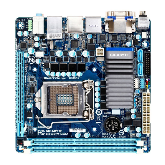
GA-H61N-USB3 Motherboard Layout F_PANEL SYS_FAN R_SPDIF F_USB2 CLR_CMOS SATA2_0 SATA2_1 F_USB1 iTE IT8728 Intel ® VGA_DVI LGA1155 USB_HDMI ATX_12V Fresco FL1009 USB_ESATA Realtek RTL8111E (Note 1) USB30_LAN AUDIO SPDIF_O CPU_FAN F_AUDIO CODEC PCIEX16 M_BIOS B_BIOS (Note 2) (Note 1) The LAN chip is located on the back of the motherboard. (Note 2) The BIOS flash ROM is located below the latch on the PCIEX16 slot. -
Page 8: Ga-H61N-Usb3 Motherboard Block Diagram
GA-H61N-USB3 Motherboard Block Diagram 1 PCI Express x16 CPU CLK+/- (100 MHz) PCIe CLK LGA1155 (100 MHz) DDR3 1333/1066/800 MHz Dual Channel Memory PCI Express Bus 2 USB 3.0/2.0 DVI-D RJ45 Realtek HDMI Fresco RTL8111E FL1009 D-Sub PCI Express Bus Dual BIOS Intel ®... -
Page 9: Chapter 1 Hardware Installation
Chapter 1 Hardware Installation Installation Precautions The motherboard contains numerous delicate electronic circuits and components which can become damaged as a result of electrostatic discharge (ESD). Prior to installation, carefully read the user's manual and follow these procedures: Prior to installation, do not remove or break motherboard S/N (Serial Number) sticker or •... -
Page 10: Product Specifications
Dual channel memory architecture Š Support for DDR3 1333/1066/800 MHz memory modules Š Support for non-ECC memory modules Š (Go to GIGABYTE's website for the latest supported memory speeds and memory modules.) Onboard Integrated Graphics Processor: Š Graphics 1 x D-Sub port 1 x DVI-D port, supporting a maximum resolution of 1920x1200 * The DVI-D port does not support D-Sub connection by adapter. - Page 11 Internal 1 x 24-pin ATX main power connector Š Connectors 1 x 4-pin ATX 12V power connector Š 2 x SATA 3Gb/s connectors Š 1 x CPU fan header Š 1 x system fan header Š 1 x front panel header Š...
- Page 12 Support for Microsoft Windows 7/Vista/XP Š ® System Form Factor Mini-ITX Form Factor; 17.0cm x 17.0cm Š * GIGABYTE reserves the right to make any changes to the product specifications and product-related in formation without prior notice. Hardware Installation - 12 -...
-
Page 13: Installing The Cpu And Cpu Cooler
Read the following guidelines before you begin to install the CPU: Make sure that the motherboard supports the CPU. • (Go to GIGABYTE's website for the latest CPU support list.) Always turn off the computer and unplug the power cord from the power outlet before installing •... - Page 14 B. Follow the steps below to correctly install the CPU into the motherboard CPU socket. Before installing the CPU, make sure to turn off the computer and unplug the power cord from the power outlet to prevent damage to the CPU. Step 1: Step 2: Gently press the CPU socket lever handle down...
-
Page 15: Installing The Cpu Cooler
1-3-2 Installing the CPU Cooler Follow the steps below to correctly install the CPU cooler on the motherboard. (The following procedure uses Intel boxed cooler as the example cooler.) ® Male Push Direction of the Arrow Sign on The Top the Male Push of Female Push Pin... -
Page 16: Installing The Memory
Make sure that the motherboard supports the memory. It is recommended that memory of the • same capacity, brand, speed, and chips be used. (Go to GIGABYTE's website for the latest supported memory speeds and memory modules.) Always turn off the computer and unplug the power cord from the power outlet before installing •... -
Page 17: Installing A Memory
1-4-2 Installing a Memory Before installing a memory module, make sure to turn off the computer and unplug the power cord from the power outlet to prevent damage to the memory module. DDR3 and DDR2 DIMMs are not compatible to each other or DDR DIMMs. Be sure to install DDR3 DIMMs on this motherboard. -
Page 18: Installing An Expansion Card
Installing an Expansion Card Read the following guidelines before you begin to install an expansion card: Make sure the motherboard supports the expansion card. Carefully read the manual that came • with your expansion card. Always turn off the computer and unplug the power cord from the power outlet before installing •... -
Page 19: Back Panel Connectors
Back Panel Connectors Optical S/PDIF Out Connector This connector provides digital audio out to an external audio system that supports digital optical audio. Before using this feature, ensure that your audio system provides an optical digital audio in connector. Coaxial S/PDIF Out Connector This connector provides digital audio out to an external audio system that supports digital coaxial audio. - Page 20 Dual Monitor Configurations for the Onboard Graphics: This motherboard provides three video output ports: D-Sub, DVI-D, and HDMI Dual monitor configurations are supported in operating system environment only, but not during the BIOS Setup or POST process. eSATA 3Gb/s Port The eSATA 3Gb/s port conforms to SATA 3Gb/s standard and is compatible with SATA 1.5Gb/s stan- dard.
-
Page 21: Internal Connectors
Internal Connectors ATX_12V F_USB1/F_USB2 SPDIF_O CPU_FAN SYS_FAN SATA2_0/1 CLR_CMOS F_PANEL PHASE LED F_AUDIO Read the following guidelines before connecting external devices: First make sure your devices are compliant with the connectors you wish to connect. • Before installing the devices, be sure to turn off the devices and your computer. Unplug the •... - Page 22 1/2) ATX_12V/ATX (2x2 12V Power Connector and 2x12 Main Power Connector) With the use of the power connector, the power supply can supply enough stable power to all the components on the motherboard. Before connecting the power connector, first make sure the power supply is turned off and all devices are properly installed.
- Page 23 3/4) CPU_FAN/SYS_FAN (Fan Headers) The motherboard has a 4-pin CPU fan header (CPU_FAN) and a 3-pin system fan header (SYS_FAN). Most fan headers possess a foolproof insertion design. When connecting a fan cable, be sure to connect it in the correct orientation (the black connector wire is the ground wire). The motherboard supports CPU fan speed control, which requires the use of a CPU fan with fan speed control design.
-
Page 24: F_Panel (Front Panel Header)
6) F_PANEL (Front Panel Header) Connect the power switch, reset switch, and system status indicator on the chassis to this header ac- cording to the pin assignments below. Note the positive and negative pins before connecting the cables. Reset Ha rd Dr i v e Activity LED Switch Power... -
Page 25: Front Panel Audio Header
7) F_AUDIO (Front Panel Audio Header) The front panel audio header supports Intel High Definition audio (HD) and AC'97 audio. You may connect your chassis front panel audio module to this header. Make sure the wire assignments of the module con- nector match the pin assignments of the motherboard header. - Page 26 9) SPDIF_O (S/PDIF Out Header) This header supports digital S/PDIF Out and connects a S/PDIF digital audio cable (provided by expan- sion cards) for digital audio output from your motherboard to certain expansion cards like graphics cards and sound cards. For example, some graphics cards may require you to use a S/PDIF digital audio cable for digital audio output from your motherboard to your graphics card if you wish to connect an HDMI display to the graphics card and have digital audio output from the HDMI display at the same time.
-
Page 27: Battery/Clearing Cmos Jumper
11) BAT (Battery) The battery provides power to keep the values (such as BIOS configurations, date, and time information) in the CMOS when the computer is turned off. Replace the battery when the battery voltage drops to a low level, or the CMOS values may not be accurate or may be lost. You may clear the CMOS values by removing the battery: 1. - Page 28 13) PHASE LED The number of lighted LEDs indicates the CPU loading. The higher the CPU loading, the more the number of lighted LEDs. To enable the Phase LED display function, please first enable Dynamic Energy Saver 2. Refer to Chapter 4, "Dynamic Energy Saver 2,"...
-
Page 29: Chapter 2 Bios Setup
To see more advanced BIOS Setup menu options, you can press <Ctrl> + <F1> in the main menu of the BIOS Setup program. To upgrade the BIOS, use either the GIGABYTE Q-Flash or @BIOS utility. Q-Flash allows the user to quickly and easily upgrade or back up BIOS without entering the operating •... -
Page 30: Startup Screen
Startup Screen The following screens may appear when the computer boots. A. The LOGO Screen (Default) Function Keys B. The POST Screen Award Modular BIOS v6.00PG Copyright (C) 1984-2011, Award Software, Inc. H61N-USB3 E5 Motherboard Model BIOS Version Function Keys <DEL>: BIOS Setup <F9>: XpressRecovery2 <F12>: Boot Menu <End>: Qflash 06/17/2011-H61-7A89WG0TC-00 SATA Mode Message:... -
Page 31: The Main Menu
The Main Menu Once you enter the BIOS Setup program, the Main Menu (as shown below) appears on the screen. Use ar- row keys to move among the items and press <Enter> to accept or enter a sub-menu. (Sample BIOS Version: E5) CMOS Setup Utility-Copyright (C) 1984-2011 Award Software MB Intelligent Tweaker(M.I.T.) Load Fail-Safe Defaults... - Page 32 The Functions of the <F11> and <F12> keys (For the Main Menu Only) F11: Save CMOS to BIOS This function allows you to save the current BIOS settings to a profile. You can create up to 8 profiles (Profile 1-8) and name each profile.
-
Page 33: Mb Intelligent Tweaker(M.i.t.)
MB Intelligent Tweaker(M.I.T.) CMOS Setup Utility-Copyright (C) 1984-2011 Award Software MB Intelligent Tweaker(M.I.T.) Item Help M.I.T Current Status [Press Enter] Menu Level Advanced Frequency Settings [Press Enter] Advanced Memory Settings [Press Enter] Advanced Voltage Settings [Press Enter] ... -
Page 34: Cpu Clock Ratio
M.I.T. Current Status This screen provides information on CPU/memory frequencies/parameters. Advanced Frequency Settings CMOS Setup Utility-Copyright (C) 1984-2011 Award Software Advanced Frequency Settings Item Help CPU Clock Ratio [30X] Menu Level CPU Frequency 3.00GHz (100x30) Advanced CPU Core Features [Press Enter] >>>>>... - Page 35 Intel(R) Turbo Boost Tech. (Note) Allows you to determine whether to enable the Intel CPU Turbo Boost technology. Auto lets the BIOS automatically configure this setting. (Default: Auto) Turbo Ratio (1-Core)/(2-Core)/(3-Core)/(4-Core) (Note) Allows you to set the CPU Turbo ratios for different number of active cores. Auto sets the CPU Turbo ratios according to the CPU specifications.
- Page 36 Bi-Directional PROCHOT (Note) Auto Lets the BIOS automatically configure this setting. (Default) Enabled When the CPU or chipset detects that an overheating is occurring, PROCHOT signals will be emitted to lower CPU performance to decrease heat production. Disabled Only allows the CPU to detect whether an overheating is occurring to emit PROCHOT sig- nals.
- Page 37 Advanced Memory Settings CMOS Setup Utility-Copyright (C) 1984-2011 Award Software Advanced Memory Settings Item Help System Memory Multiplier (SPD) [Auto] Menu Level Memory Frequency (Mhz) 1333 1333 Performance Enhance [Turbo] DRAM Timing Selectable (SPD) [Auto] Profile DDR Voltage 1.5V Profile VTT Voltage 1.05V x Channel Interleaving Auto x Rank Interleaving...
- Page 38 >>>>> Channel A/B Timing Settings CMOS Setup Utility-Copyright (C) 1984-2011 Award Software Channel A Timing Settings Item Help >>>>> Channel A Standard Timing Control Menu Level x CAS Latency Time Auto x tRCD Auto x tRP Auto x tRAS Auto >>>>>...
- Page 39 tFAW Options are: Auto (default), 1~63. Command Rate(CMD) Options are: Auto (default), 1~3. >>>>> Channel A/B Misc Timing Control IO Latency Options are: Auto (default), 1~31. Round Trip Latency Options are: Auto (default), 1~255. Advanced Voltage Settings CMOS Setup Utility-Copyright (C) 1984-2011 Award Software Advanced Voltage Settings Item Help ****** Mother Board Voltage Control ******...
-
Page 40: Miscellaneous Settings
Miscellaneous Settings CMOS Setup Utility-Copyright (C) 1984-2011 Award Software Miscellaneous Settings Item Help Isochronous Support [Enabled] Menu Level Virtualization Technology (Note) [Enabled] hi: Move Enter: Select +/-/PU/PD: Value F10: Save ESC: Exit F1: General Help F5: Previous Values F6: Fail-Safe Defaults F7: Optimized Defaults Isochronous Support Determines whether to enable specific streams within the CPU and Chipset. -
Page 41: Standard Cmos Features
Standard CMOS Features CMOS Setup Utility-Copyright (C) 1984-2011 Award Software Standard CMOS Features Item Help Date (mm:dd:yy) Fri, Jun 17 2011 Menu Level Time (hh:mm:ss) 10:26:46 IDE Channel 0 Master [None] IDE Channel 1 Master [None] IDE Channel 3 Master [None] Halt On [All Errors]... - Page 42 Landing Zone Landing zone. Sector Number of sectors. Halt On Allows you to determine whether the system will stop for an error during the POST. All Errors Whenever the BIOS detects a non-fatal error the system boot will stop. (Default) No Errors The system boot will not stop for any error.
-
Page 43: Advanced Bios Features
Advanced BIOS Features CMOS Setup Utility-Copyright (C) 1984-2011 Award Software Advanced BIOS Features Item Help Hard Disk Boot Priority [Press Enter] Menu Level Quick Boot [Disabled] EFI CD/DVD Boot Option [Auto] First Boot Device [Hard Disk] Second Boot Device [CDROM] Third Boot Device [USB-FDD]... - Page 44 Allows you to set a delay time for the BIOS to initialize the hard drive as the system boots up. The ad- justable range is from 0 to 15 seconds. (Default: 0) Full Screen LOGO Show Allows you to determine whether to display the GIGABYTE Logo at system startup. Disabled displays normal POST message. (Default: Enabled) Init Display First Specifies the first initiation of the monitor display from the installed PCI Express graphics card or the onboard graphics.
-
Page 45: Integrated Peripherals
Integrated Peripherals CMOS Setup Utility-Copyright (C) 1984-2011 Award Software Integrated Peripherals Item Help SATA AHCI Mode [IDE] Menu Level SATA Port0-1 Native Mode [Enabled] USB Controllers [Enabled] USB Legacy Function [Enabled] USB Storage Function [Enabled] Azalia Codec [Auto] Onboard H/W LAN [Enabled] ... - Page 46 Onboard H/W LAN Enables or disables the onboard LAN function. (Default: Enabled) If you wish to install a 3rd party add-in network card instead of using the onboard LAN, set this item to Disabled. SMART LAN CMOS Setup Utility-Copyright (C) 1984-2011 Award Software SMART LAN Item Help Start detecting at Port..
-
Page 47: Power Management Setup
Power Management Setup CMOS Setup Utility-Copyright (C) 1984-2011 Award Software Power Management Setup Item Help ACPI Suspend Type [S3(STR)] Menu Level Soft-Off by PWR-BTTN [Instant-Off] PME Event Wake Up [Enabled] Resume by Alarm [Disabled] Date (of Month) Alarm Everyday Time (hh:mm:ss) Alarm 0 : 0 : 0 HPET Support [Enabled]... - Page 48 HPET Support (Note) Enables or disables High Precision Event Timer (HPET) for Windows 7/Vista operating system. (Default: Enabled) HPET Mode (Note) Allows you to select the HPET mode for your Windows 7/Vista operating system. Select 32-bit mode when you install 32-bit Windows 7/Vista; select 64-bit mode when you install 64-bit Windows 7/Vista. This item is configurable only when the HPET Support is set to Enabled.
-
Page 49: Pc Health Status
PC Health Status CMOS Setup Utility-Copyright (C) 1984-2011 Award Software PC Health Status Item Help Vcore 1.172V Menu Level DDR15V 1.516V +12V 11.779V 1.076V Current System Temperature Current CPU Temperature Current CPU FAN Speed 3375 RPM Current SYSTEM FAN Speed 0 RPM CPU Smart FAN Control [Normal]... -
Page 50: Load Fail-Safe Defaults
Load Fail-Safe Defaults CMOS Setup Utility-Copyright (C) 1984-2011 Award Software MB Intelligent Tweaker(M.I.T.) Load Fail-Safe Defaults Standard CMOS Features Load Optimized Defaults Advanced BIOS Features Set Supervisor Password Integrated Peripherals Set User Password Power Management Setup Save &... -
Page 51: Set Supervisor/User Password
2-11 Set Supervisor/User Password CMOS Setup Utility-Copyright (C) 1984-2011 Award Software MB Intelligent Tweaker(M.I.T.) Load Fail-Safe Defaults Standard CMOS Features Load Optimized Defaults Advanced BIOS Features Set Supervisor Password Integrated Peripherals Set User Password Power Management Setup Save &... -
Page 52: Save & Exit Setup
2-12 Save & Exit Setup CMOS Setup Utility-Copyright (C) 1984-2011 Award Software MB Intelligent Tweaker(M.I.T.) Load Fail-Safe Defaults Standard CMOS Features Load Optimized Defaults Save to CMOS and EXIT (Y/N)? Y Advanced BIOS Features Set Supervisor Password Integrated Peripherals Set User Password ... -
Page 53: Chapter 3 Drivers Installation
After "Xpress Install" installs all of the drivers, a dialog box will appear asking whether to install • new GIGABYTE utilities. Click Yes to automatically install the utilities. Or click No if you want to manually select the utilities to install on the Application Software page later. -
Page 54: Application Software
Application Software This page displays all the utilities and applications that GIGABYTE develops and some free software. You can click the Install button on the right of an item to install it. Technical Manuals This page provides GIGABYTE's application guides, content descriptions for this driver disk, and the mother- board manuals. -
Page 55: Contact
Contact For the detailed contact information of the GIGABYTE Taiwan headquarter or worldwide branch offices, click the URL on this page to link to the GIGABYTE website. System This page provides the basic system information. - 55 - Drivers Installation... -
Page 56: Download Center
The latest version of the BIOS, drivers, or applications will be displayed. New Utilities This page provides a quick link to GIGABYTE's lately developed utilities for users to install. You can click the Install button on the right of an item to install it. -
Page 57: Chapter 4 Unique Features
Chapter 4 Unique Features Xpress Recovery2 Xpress Recovery2 is a utility that allows you to quickly compress and back up your system data and perform restoration of it. Supporting NTFS, FAT32, and FAT16 file systems, Xpress Recovery2 can back up data on PATA and SATA hard drives and restore it. - Page 58 Step 3: Step 4: When partitioning your hard drive, make sure to After the operating system is installed, click Start, leave unallocated space (10 GB or more is recom- right-click the Computer and select Manage. Go to mended; actual size requirements vary, depending Disk Management to check disk allocation.
- Page 59 D. Using the Restore Function in Xpress Recovery2 Select RESTORE to restore the backup to your hard drive in case the system breaks down. The RESTORE option will not be present if no backup is created before. E. Removing the Backup Step 1: Step 2: If you wish to remove the backup file, select...
-
Page 60: Bios Update Utilities
4-2-1 Updating the BIOS with the Q-Flash Utility A. Before You Begin From GIGABYTE's website, download the latest compressed BIOS update file that matches your moth- erboard model. Extract the file and save the new BIOS file (e.g. h61nusb3.f1) to your USB flash drive, or hard drive. - Page 61 B. Updating the BIOS When updating the BIOS, choose the location where the BIOS file is saved. The following procedure as- sumes that you save the BIOS file to a USB flash drive. Step 1: Insert the USB flash drive containing the BIOS file into the computer. In the main menu of Q-Flash, use the up or down arrow key to select Update BIOS from Drive and press <Enter>.
- Page 62 Step 4: Press <Esc> and then <Enter> to exit Q-Flash and reboot the system. As the system boots, you should see the new BIOS version is present on the POST screen. Step 5: During the POST, press <Delete> to enter BIOS Setup. Select Load Optimized Defaults and press <Enter> to load BIOS defaults.
-
Page 63: Updating The Bios With The @Bios Utility
BIOS or a system that is unable to start. Do not use the G.O.M. (GIGABYTE Online Management) function when using @BIOS. GIGABYTE product warranty does not cover any BIOS damage or system failure resulting from an inad- equate BIOS flashing. -
Page 64: Easytune 6
EasyTune 6 GIGABYTE's EasyTune 6 is a simple and easy-to-use interface that allows users to fine-tune their system settings or do overclock/overvoltage in Windows environment. The user-friendly EasyTune 6 interface also includes tabbed pages for CPU and memory information, letting users read their system-related information without the need to install additional software. -
Page 65: Dynamic Energy Saver ™ 2
The Dynamic Energy Saver 2 Interface ™ A. Meter Mode In Meter Mode, GIGABYTE Dynamic Energy Saver 2 shows how much power they have saved in a set pe- ™ riod of time. 12 13 14... - Page 66 B. Total Mode In Total Mode, users are able to see how much total power savings they have accumulated in a set period of time since activating Dynamic Energy Saver 2 for the first time ™ (Note 3) 11 12 13 Total Mode - Button Information Table Button Description Dynamic Energy Saver On/Off Switch (Default: Off)
-
Page 67: Q-Share
Q-Share, you are able to share your data with computers on the same network, making full use of Internet resources. Directions for using Q-Share After installing Q-Share from the motherboard driver disk, go to Start>All Programs>GIGABYTE>Q-Share. exe to launch the Q-Share tool. Find the Q-Share icon in the notification area and right-click on this icon to configure the data sharing settings. -
Page 68: Smart 6
Smart 6 ™ GIGABYTE Smart 6 is designed with user-friendliness in mind, and offers a combination of 6 innovative ™ (Note 1) software utilities that provide easier and smarter PC system management. Smart 6 allows you to speed up ™... - Page 69 SMART Recovery 2 Smart Recovery 2 allows you to back up a partition as an image file every hour. You can use these images to restore your system or files when needed. The Smart Recovery 2 main menu: Button Function Settings Allows you to select the source and destination partition Backup Now...
- Page 70 Recovering your system with Smart Recovery 2 (Windows 7 only): Steps: 1. Click the System Recovery button on the main menu. 2. Select the partition where your backup is saved. 3. Use the time slider to select a time point. 4.
- Page 71 SMART Recorder SMART Recorder monitors and records the activities in a system such as the time when the computer was turned on/off or even when large data files were moved within the hard drive or copied to an external storage device (Note 2) Instructions: Select the Enable check box at the bottom of the ON/OFF Recorder...
-
Page 72: Auto Green
Auto Green Auto Green is an easy-to-use tool that provides users with simple options to enable system power savings via a Bluetooth cell phone. When the phone is out of the range of the computer's Bluetooth receiver, the sys- tem will enter the specified power saving mode. The Configuration dialog box: First, you have to set your Bluetooth cell phone as a portable key. -
Page 73: Cloud Oc
Cloud OC Cloud OC is an easy-to-use overclocking utility designed for system overclock- (Note 1) ing via virtually any Internet-connected device, such as a smart phone, iPhone, note- book PC, etc. By simply connecting to an Internet browser via LAN, wireless LAN, or Bluetooth and logging in to the Cloud OC server, you can easily access three major functions of Cloud (Note 2) - Page 74 Unique Features - 74 -...
-
Page 75: Chapter 5 Appendix
Chapter 5 Appendix Configuring Audio Input and Output 5-1-1 Configuring 2/4/5.1/7.1-Channel Audio The motherboard provides three audio jacks on the back panel which support 2/4/5.1/7.1 -channel audio. The picture to the right shows (Note) the default audio jack assignments. Line In The integrated HD (High Definition) audio provides jack retasking capa- Front Speaker Out bility that allows the user to change the function for each jack through... - Page 76 The pictures to the right show the 7.1-channel speak- 7.1-Channel Speakers: er configurations. Front Speaker Out Rear Speaker Out Center/Subwoofer Speaker Out Side Speaker Out Step 2: Connect an audio device to an audio jack. The The cur- rent connected device is dialog box appears. Select the device according to the type of device you connect.
- Page 77 C. Activating an AC'97 Front Panel Audio Module If your chassis provides an AC'97 front panel audio mod- ule, to activate the AC'97 functionality, click the tool icon on the Speaker Configuration tab. On the Connector Settings dialog box, select the Disable front panel jack detection check box.
-
Page 78: Configuring S/Pdif Out
5-1-2 Configuring S/PDIF Out The S/PDIF Out jack can transmit audio signals to an external decoder for decoding to get the best audio quality. 1. Connecting a S/PDIF Out Cable: Connect a S/PDIF coaxial cable or a S/PDIF optical cable (either one) to the corresponding S/PDIF out con- nector as shown below and an external decoder for transmitting the S/PDIF digital audio signals. -
Page 79: Configuring Microphone Recording
5-1-3 Configuring Microphone Recording Step 1: After installing the audio driver, the HD Audio Manager icon will appear in the notification area. Double-click the icon to access the HD Audio Manager. Step 2: Connect your microphone to the Mic in jack (pink) on the back panel or the Mic in jack (pink) on the front panel. - Page 80 Step 5: After completing the settings above, click Start, point to All Programs, point to Accessories, and then click Sound Recorder to begin the sound recording. * Enabling Stereo Mix If the HD Audio Manager does not display the recording device you wish to use, refer to the steps below. The following steps explain how to enable Stereo Mix (which may be needed when you want to record sound from your computer).
-
Page 81: Using The Sound Recorder
Step 4: Now you can access the HD Audio Manager to config- ure Stereo Mix and use Sound Recorder to record the sound. 5-1-4 Using the Sound Recorder A. Recording Sound 1. Make sure you have connected the sound input device (e.g. microphone) to the computer. 2. -
Page 82: Troubleshooting
Troubleshooting 5-2-1 Frequently Asked Questions To read more FAQs for your motherboard, please go to the Support & Downloads\FAQ page on GIGABYTE's website. Q: In the BIOS Setup program, why are some BIOS options missing? A: Some advanced options are hidden in the BIOS Setup program. Press <Delete> to enter BIOS Setup during the POST. In the Main Menu, press <Ctrl>+<F1>... -
Page 83: Troubleshooting Procedure
5-2-2 Troubleshooting Procedure If you encounter any troubles during system startup, follow the troubleshooting procedure below to solve the problem. START Turn off the power. Remove all peripherals, connecting cables, and power cord etc. Make sure the motherboard does not short-circuit with the chassis or Isolate the short circuit. - Page 84 The power supply, CPU or When the computer is turned on, is the CPU cooler running? CPU socket might fail. The problem is verified and solved. The graphics card, expansion slot, or monitor Check if there is display on your monitor. might fail.
- Page 85 - 85 - Appendix...
- Page 86 Appendix - 86 -...
- Page 87 Web address: http://latam.giga-byte.com TEL: +86-24-83992901 • Giga-Byte SINGAPORE PTE. LTD. - Singapore FAX: +86-24-83992909 WEB address : http://www.gigabyte.sg • GIGABYTE TECHNOLOGY (INDIA) LIMITED - India • Thailand WEB address : http://www.gigabyte.in WEB address : http://th.giga-byte.com • Saudi Arabia • Vietnam WEB address : http://www.gigabyte.com.sa...
- Page 88 WEB address : http://www.gigabyte.com.gr WEB address : http://www.gigabyte.kz • Czech Republic You may go to the GIGABYTE website, select your language WEB address : http://www.gigabyte.cz in the language list on the top right corner of the website. • GIGABYTE Global Service System...