Table of Contents
Advertisement
Copyright
This publication, including all photographs, illustrations and software, is protected
under international copyright laws, with all rights reserved. Neither this manual, nor
any of the material contained herein, may be reproduced without written consent of
the author.
Version 2.0
Disclaimer
The information in this document is subject to change without notice. The manufac-
turer makes no representations or warranties with respect to the contents hereof and
specifically disclaims any implied warranties of merchantability or fitness for any
particular purpose. The manufacturer reserves the right to revise this publication and
to make changes from time to time in the content hereof without obligation of the
manufacturer to notify any person of such revision or changes.
Trademark Recognition
Microsoft, MS-DOS and Windows are registered trademarks of Microsoft Corp.
MMX, Pentium, Pentium-II, Pentium-III, Celeron are registered trademarks of Intel
Corporation.
Other product names used in this manual are the properties of their respective
owners and are acknowledged.
Federal Communications Commission (FCC)
This equipment has been tested and found to comply with the limits for a Class B
digital device, pursuant to Part 15 of the FCC Rules. These limits are designed to
provide reasonable protection against harmful interference in a residential installa-
tion. This equipment generates, uses, and can radiate radio frequency energy and, if
not installed and used in accordance with the instructions, may cause harmful inter-
ference to radio communications. However, there is no guarantee that interference
will not occur in a particular installation. If this equipment does cause harmful
interference to radio or television reception, which can be determined by turning the
equipment off and on, the user is encouraged to try to correct the interference by one
or more of the following measures:
•
Reorient or relocate the receiving antenna
•
Increase the separation between the equipment and the receiver
•
Connect the equipment onto an outlet on a circuit different from that to
which the receiver is connected
•
Consult the dealer or an experienced radio/TV technician for help
Shielded interconnect cables and a shielded AC power cable must be employed with
this equipment to ensure compliance with the pertinent RF emission limits govern-
ing this device. Changes or modifications not expressly approved by the system's
manufacturer could void the user's authority to operate the equipment.
Preface
Preface
Advertisement
Table of Contents

Related Manuals for ECS G31T-M


Summary of Contents for ECS G31T-M
- Page 1 Preface Copyright This publication, including all photographs, illustrations and software, is protected under international copyright laws, with all rights reserved. Neither this manual, nor any of the material contained herein, may be reproduced without written consent of the author. Version 2.0 Disclaimer The information in this document is subject to change without notice.
-
Page 2: Declaration Of Conformity
Declaration of Conformity This device complies with part 15 of the FCC rules. Operation is subject to the following conditions: • This device may not cause harmful interference, and • This device must accept any interference received, including interfer- ence that may cause undesired operation Canadian Department of Communications This class B digital apparatus meets all requirements of the Canadian Interference- causing Equipment Regulations. -
Page 3: Table Of Contents
T T T T T ABLE OF CONTENTS ABLE OF CONTENTS ABLE OF CONTENTS ABLE OF CONTENTS ABLE OF CONTENTS Preface Chapter 1 Introducing the Motherboard Introduction..................1 Feature....................2 Motherboard Components.............4 Chapter 2 7 7 7 7 7 Installing the Motherboard Safety Precautions................7 Choosing a Computer Case............7 Installing the Motherboard in a Case..........7... - Page 4 Integrated Peripherals............34 Power Management Setup..........35 PCI/PnP Setup..............37 PC Health Status...............37 Frequency/Voltage Control..........40 Load Default Settings............41 Supervisor Password............41 User Password..............42 Save & Exit Setup..............42 Exit Without Saving............42 Updating the BIOS.............43 Chapter 4 45 45 45 45 Using the Motherboard Software About the Software DVD-ROM/CD-ROM.........45 Auto-installing under Windows XP/Vista/7.......45 Running Setup..............46 Manual Installation................48...
-
Page 5: Introducing The Motherboard
Chapter 1 Introducing the Motherboard Introduction Thank you for choosing the G31T-M motherboard. This motherboard is a high performance, enhanced function motherboard designed to support the LGA775 socket ® ™ ® Intel Yorkfield/Wolfdale/Core 2 Quad (Q6600/Q6700 G0)/Pentium Dual-Core/ ® Celeron 4xx Series processors for high-end business or personal desktop markets. -
Page 6: Feature
Feature Processor ® ™ The motherboard uses an LGA775 type of Intel Yorkfield/Wolfdale/Core ® ® Quad (Q6600/Q6700 G0)/Pentium Dual-Core/Celeron 4xx Series that car- ries the following features: ® ™ • Accommodates Intel Yorkfield/Wolfdale/Core 2 Quad (Q6600/ ® ® Q6700 G0)/Pentium Dual-Core/Celeron 4xx Series processors •... - Page 7 Audio (optional) This motherboard may support either of the following Audio chipsets: • 7.1 + 2 Channel High Definition Audio Codec • All DACs support 192K/96K/48K/44.1KHz DAC sample rate • Software selectable 2.5V/3.75V VREFOUT • Meets Microsoft WHQL/WLP 2.x audio requirements •...
-
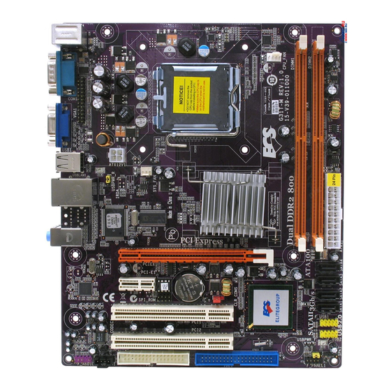
Page 8: Motherboard Components
Motherboard Components Introducing the Motherboard... - Page 9 Table of Motherboard Components LABEL COMPONENTS ® LGA775 socket for Intel Yorkfield/Wolfdale/Core 1. CPU Socket ® Quad (Q6600/Q6700 G0)/Pentium Dual-Core/ ® Celeron 4xx Series processors 2. CPU_FAN CPU cooling fan connector 3. DIMM1~2 240-pin DDR2 SDRAM slots 4. ATX1 Standard 24-pin ATX power connector 5.
- Page 10 Memo Introducing the Motherboard...
-
Page 11: Installing The Motherboard
Chapter 2 Installing the Motherboard Safety Precautions • Follow these safety precautions when installing the motherboard • Wear a grounding strap attached to a grounded device to avoid dam- age from static electricity • Discharge static electricity by touching the metal case of a safely grounded object before working on the motherboard •... -
Page 12: Checking Jumper Settings
Do not over-tighten the screws as this can stress the motherboard. Checking Jumper Settings This section explains how to set jumpers for correct configuration of the motherboard. Setting Jumpers Use the motherboard jumpers to set system configuration options. Jumpers with more than one pin are numbered. -
Page 13: Checking Jumper Settings
Checking Jumper Settings The following illustration shows the location of the motherboard jumpers. Pin 1 is labeled. Jumper Settings Jumper Type Description Setting (default) 1-2: NORMAL 2-3: CLEAR CMOS CLR_CMOS 3-pin Clear CMOS Before clearing the CLR_CMOS CMOS, make sure to turn off the system. -
Page 14: Installing Hardware
Installing Hardware Installing the Processor Caution: When installing a CPU heatsink and cooling fan make sure that you DO NOT scratch the motherboard or any of the surface- mount resistors with the clip of the cooling fan. If the clip of the cooling fan scrapes across the motherboard, you may cause serious damage to the motherboard or its components. -
Page 15: Cpu Installation Procedure
CPU Installation Procedure The following illustration shows CPU installation components. A. Read and follow the instructions shown on the sticker on the CPU cap. B. Unload the cap · Use thumb & forefinger to hold the lifting tab of the cap. ·... -
Page 16: Installing Memory Modules
Installing Memory Modules This motherboard accommodates two memory modules. It can support two 240-pin DDR2 800/667. The total memory capacity is 4 GB. DDR2 SDRAM memory module table Memory module Memory Bus DDR2 667 333 MHz DDR2 800 400 MHz You must install at least one module in any of the two slots. - Page 17 Table A: DDR2 (memory module) QVL (Qualified Vendor List) The following DDR2 800/667 memory modules have been tested and qualified for use with this motherboard. Type Size Vendor Module Name Infineon HYS64T325001HU-3-A 256 MB Ramaxel 5NB31 D9DCG A-DATA Eipida E5108AE-6E-E A-DATA AD29608A88-3EG CORSAIR...
-
Page 18: Expansion Slots
Expansion Slots Installing Add-on Cards The slots on this motherboard are designed to hold expansion cards and connect them to the system bus. Expansion slots are a means of adding or enhancing the motherboard’s features and capabilities. With these efficient facilities, you can in- crease the motherboard’s capabilities by adding hardware that performs tasks that are not part of the basic system. - Page 19 Follow these instructions to install an add-on card: Remove a blanking plate from the system case corresponding to the slot you are going to use. Install the edge connector of the add-on card into the expansion slot. Ensure that the edge connector is correctly seated in the slot. Secure the metal bracket of the card to the system case with a screw.
-
Page 20: Connecting Optional Devices
Connecting Optional Devices Refer to the following for information on connecting the motherboard’s optional devices: F_AUDIO1: Front Panel Audio header for Azalia This header allows the user to install auxiliary front-oriented microphone and line- out ports for easier access. Signal Name Signal Name PORT 1L AUD_GND... - Page 21 F_USB1~2: Front Panel USB headers The motherboard has four USB ports installed on the rear edge I/O port array. Additionally, some computer cases have USB ports at the front of the case. If you have this kind of case, use auxiliary USB connector to connect the front-mounted ports to the motherboard.
- Page 22 LPT1: Onboard parallel port header This is a header that can be used to connect to the printer, scanner or other devices. Signal Name Signal Name STROBE ERROR INIT SLCTIN Ground Ground Ground Ground Ground Ground BUSK Ground Ground SLCT SPDIFO1: SPDIF out header This is an optional header that provides an S/PDIF (Sony/Philips Digital Interface) output to digital multimedia device through optical fiber or coaxial connector.
-
Page 23: Installing A Hard Disk Drive/Cd-Rom/Sata Hard Drive
Installing a Hard Dish Drive/CD-ROM/SATA Hard Drive This section describes how to install IDE devices such as a hard disk drive and a CD- ROM drive. About IDE Devices Your motherboard has one IDE channel interface. IDE1: IDE Connector This motherboard supports four high data transfer SATA ports with each runs up to 3.0 Gb/s. -
Page 24: Installing A Floppy Diskette Drive
Refer to the illustration below for proper installation: Attach either cable end to the connector on the motherboard. Attach the other cable end to the SATA hard drive. Attach the SATA power cable to the SATA hard drive and connect the other end to the power supply. -
Page 25: Connecting I/O Devices
Connecting I/O Devices The backplane of the motherboard has the following I/O ports: PS2 Mouse Use the upper PS/2 port to connect a PS/2 pointing device. PS2 Keyboard Use the lower PS/2 port to connect a PS/2 keyboard. Serial Port Use the COM port to connect serial devices such as mice or (COM1) fax/modems. -
Page 26: Connecting Case Components
Connecting Case Components After you have installed the motherboard into a case, you can begin connecting the motherboard components. Refer to the following: Connect the CPU cooling fan cable to CPU_FAN. Connect the system cooling fan connector to SYS_FAN. Connect the case switches and indicator LEDs to the F_PANEL1. Connect the case speaker cable to SPK1. -
Page 27: Atx 12V Power Connector
CPU_FAN: CPU Cooling FAN Power Connector Signal Name Function System Ground Power +12V +12V Sense Sensor Users please note that the fan connector supports the CPU cooling fan of 1.1A ~ 2.2A (26.4W max) at +12V. SYS_FAN: System Cooling FAN Power Connector Signal Name Function System Ground... -
Page 28: Spk1: Internal Speaker
SPK1: Internal speaker Signal Name Signal Front Panel Header The front panel header (F_PANEL1) provides a standard set of switch and LED headers commonly found on ATX or micro-ATX cases. Refer to the table below for information: Signal Function Signal Function HD_LED_P Hard disk LED (+) FP PWR/SLP *MSG LED (+) -
Page 29: Using Bios
Chapter 3 Using BIOS About the Setup Utility The computer uses the latest “American Megatrends Inc. ” BIOS with support for Windows Plug and Play. The CMOS chip on the motherboard contains the ROM setup instructions for configuring the motherboard BIOS. The BIOS (Basic Input and Output System) Setup Utility displays the system’s configuration status and provides you with options to set system parameters. -
Page 30: Resetting The Default Cmos Values
Press the delete key to access the BIOS Setup Utility. CMOS Setup Utility -- Copyright (C) 1985-2005, American Megatrends, Inc. Standard CMOS Setup Frequency/Voltage Control Advanced Setup Load Default Settings Advanced Chipset Setup Supervisor Password Integrated Peripherals User Password Power Management Setup Save &... -
Page 31: Using Bios
Using BIOS When you start the Setup Utility, the main menu appears. The main menu of the Setup Utility displays a list of the options that are available. A highlight indicates which option is currently selected. Use the cursor arrow keys to move the highlight to other options. -
Page 32: Standard Cmos Setup
For the purpose of better product maintenance, we reserve the right to change the BIOS items presented in the manual. The BIOS setup screens shown in this chapter are for reference only. Please visit our website for updated manual. Standard CMOS Setup This option displays basic information about your system. - Page 33 CMOS SETUP UTILITY – Copyright (C) 1985-2005, American Megatrends, Inc. Primary IDE Master Primary IDE Master Help Item Device : Hard Disk Vendor: ST3160812AS Size: 160.0GB Select the type LBA Mode: Supported of device connected Block Mode: 16Sectors to the system. PIO Mode: Async DMA: Multiword DMA-2 Ultra DMA: Ultra DMA-6...
-
Page 34: Advanced Setup
IDE BusMaster (Enabled) This item enables or disables the DMA under DOS mode. We recommend you to leave this item at the default value. Drive A (1 ..44 MB 3 ” ) This item defines the characteristics of any diskette drive attached to the system. You can connect one diskette drive. - Page 35 Quick Power on Self Test (Enabled) Enable this item to shorten the power on testing (POST) and have your system start up faster. You might like to enable this item after you are confident that your system hardware is operating smoothly. Boot Up Numlock Status (On) This item defines if the keyboard Num Lock key is active when your system is started.
- Page 36 Removable Drives (Press Enter) Scroll to this item and press <Enter> to view the following screen: CMOS Setup Utility - Copyright (C) 1985-2005, American Megatrends, Inc. Removable Drives Removable Drives Help Item 1st Drive 1st FLOPPY DRIVE Specifies the boot sequence from the available devices.
-
Page 37: Advanced Chipset Setup
Advanced Chipset Setup This page sets up more advanced information about your system. Handle this page with caution. Any changes can affect the operation of your computer. CMOS Setup Utility - Copyright (C) 1985-2005, American Megatrends, Inc. Advanced Chipset Setup DRAM Frequency Auto Help Item... -
Page 38: Integrated Peripherals
Integrated Peripherals This page sets up some parameters for peripheral devices connected to the system. CMOS Setup Utility - Copyright (C) 1985-2005, American Megatrends, Inc. Integrated Peripherals Onboard IDE Controller Enabled Help Item Onboard SATA Controller Enabled Onboard LAN Function Enabled DISABLED: disables inte- Onboard LAN Boot ROM... -
Page 39: Power Management Setup
Parallel Port Mode (ECP) Use this item to select the parallel port mode. You can select Normal (Standard Parallel Port), ECP (Extended Capabilities Port), EPP (Enhanced Parallel Port), or BPP (Bi-Directional Parallel Port). ECP Mode DMA Channel (DMA3) Use this item to assign the DMA Channel under ECP Mode function. Parallel Port IRQ (IRQ7) Use this item to assign IRQ to the parallel port. - Page 40 Soft-Off By PWR-BTTN (Delay 4 Sec) Under ACPI (Advanced Configuration and Power management Interface) you can create a software power down. In a software power down, the system can be resumed by Wake Up Alarms. This item lets you install a software power down that is con- trolled by the power button on your system.
-
Page 41: Pci/Pnp Setup
PCI / PnP Setup This page sets up some parameters for devices installed on the PCI bus and those utilizing the system plug and play capability. CMOS Setup Utility - Copyright (C) 1985-2005, American Megatrends, Inc. PCI / PnP Setup Help Item Init Display First Allocate IRQ to PCI VGA... - Page 42 This item allows you to enable/disable the control of the system fan speed by chang- ing the fan voltage. ECS supports the latest PECI host technology. While using Wolfdale or Yorkfield CPU, the original images of the BIOS item “PC Health Status”...
- Page 43 CMOS Setup Utility - Copyright (C) 1985-2005, American Megatrends, Inc. Smart Fan Function Help Item SMART Fan Control Enabled SMART Fan start PWM value SMART Fan start Offset (-) Options CPU DeltaT Disabled Fan1 Slope PWM value/1 Unit Enabled Fan1 Full Speed Offset (-) SMART Fan2 Control Disabled : Move...
-
Page 44: Frequency/Voltage Control
Frequency/Voltage Control This page enables you to set the clock speed and system bus for your system. The clock speed and system bus are determined by the kind of processor you have in- stalled in your system. CMOS Setup Utility - Copyright (C) 1985-2005, American Megatrends, Inc. Frequency/Voltage Control Help item Manufacturer : Intel... -
Page 45: Load Default Settings
Load Default Settings This option opens a dialog box that lets you install stability-oriented defaults for all appropriate items in the Setup Utility. Select <OK> and then press <Enter> to install the defaults. Select <Cancel> and then press <Enter> to not install the defaults. -
Page 46: User Password
User Password This page helps you install or change a password. CMOS Setup Utility - Copyright (C) 1985-2005, American Megatrends, Inc. User Password User Password : Not Installed Help item : Move Enter : Select +/-/: Value F10: Save ESC: Exit F1:General Help F9: Load Default Settings User Password (Not Installed) -
Page 47: Updating The Bios
Updating the BIOS You can download and install updated BIOS for this motherboard from the manufacturer’s Web site. New BIOS provides support for new peripherals, improve- ments in performance, or fixes for known bugs. Install new BIOS as follows: If your motherboard has a BIOS protection jumper, change the setting to allow BIOS flashing. - Page 48 Memo Using BIOS...
-
Page 49: Using The Motherboard Software
Chapter 4 Using the Motherboard Software About the Software DVD-ROM/CD-ROM The support software DVD-ROM/CD-ROM that is included in the motherboard package contains all the drivers and utility programs needed to properly run the bundled products. Below you can find a brief description of each software program, and the location for your motherboard version. -
Page 50: Running Setup
Drivers Tab Setup Click the Setup button to run the software installation program. Select from the menu which software you want to install. Browse CD The Browse CD button is the standard Windows command that al- lows you to open Windows Explorer and show the contents of the support disk. - Page 51 Click Next. The following screen appears: Check the box next to the items you want to install. The default options are recom- mended. Click Next run the Installation Wizard. An item installation screen appears: Follow the instructions on the screen to install the items. Drivers and software are automatically installed in sequence.
-
Page 52: Manual Installation
Windows Vista/7 will appear below UAC (User Account Control) message after the system restart. You must select “Allow” to install the next driver. Continue this process to complete the drivers installation. Manual Installation Insert the disk in the DVD-ROM/CD-ROM drive and locate the PATH.DOC file in the root directory. -
Page 53: Trouble Shooting
Chapter 5 Trouble Shooting Start up problems during assembly After assembling the PC for the first time you may experience some start up problems. Before calling for technical support or returning for warranty, this chapter may help to address some of the common questions using some basic troubleshooting tips. -
Page 54: Maintenance And Care Tips
c) The PC suddenly shuts down while booting up. 1. The CPU may experience overheating so it will shutdown to protect itself. Ensure the CPU fan is working properly. 2. From the BIOS setting, try to disable the Smartfan function to let the fan run at default speed. - Page 56 Memo Trouble Shooting...