Table of Contents
Advertisement
Copyright
This publication, including all photographs, illustrations and software, is protected
under international copyright laws, with all rights reserved. Neither this manual, nor
any of the material contained herein, may be reproduced without written consent of
the author.
Version 2.0
Disclaimer
The information in this document is subject to change without notice. The manufac-
turer makes no representations or warranties with respect to the contents hereof and
specifically disclaims any implied warranties of merchantability or fitness for any
particular purpose. The manufacturer reserves the right to revise this publication and
to make changes from time to time in the content hereof without obligation of the
manufacturer to notify any person of such revision or changes.
Trademark Recognition
Microsoft, MS-DOS and Windows are registered trademarks of Microsoft Corp.
MMX, Pentium, Pentium-II, Pentium-III, Celeron are registered trademarks of Intel
Corporation.
Other product names used in this manual are the properties of their respective
owners and are acknowledged.
Federal Communications Commission (FCC)
This equipment has been tested and found to comply with the limits for a Class B
digital device, pursuant to Part 15 of the FCC Rules. These limits are designed to
provide reasonable protection against harmful interference in a residential installa-
tion. This equipment generates, uses, and can radiate radio frequency energy and, if
not installed and used in accordance with the instructions, may cause harmful inter-
ference to radio communications. However, there is no guarantee that interference
will not occur in a particular installation. If this equipment does cause harmful
interference to radio or television reception, which can be determined by turning the
equipment off and on, the user is encouraged to try to correct the interference by one
or more of the following measures:
•
Reorient or relocate the receiving antenna
•
Increase the separation between the equipment and the receiver
•
Connect the equipment onto an outlet on a circuit different from that to
which the receiver is connected
•
Consult the dealer or an experienced radio/TV technician for help
Shielded interconnect cables and a shielded AC power cable must be employed with
this equipment to ensure compliance with the pertinent RF emission limits governing
this device. Changes or modifications not expressly approved by the system's manu-
facturer could void the user's authority to operate the equipment.
Preface
Preface
Advertisement
Table of Contents

Related Manuals for ECS G45T-M2


Summary of Contents for ECS G45T-M2
- Page 1 Preface Copyright This publication, including all photographs, illustrations and software, is protected under international copyright laws, with all rights reserved. Neither this manual, nor any of the material contained herein, may be reproduced without written consent of the author. Version 2.0 Disclaimer The information in this document is subject to change without notice.
-
Page 2: Declaration Of Conformity
Declaration of Conformity This device complies with part 15 of the FCC rules. Operation is subject to the following conditions: • This device may not cause harmful interference, and • This device must accept any interference received, including interfer- ence that may cause undesired operation Canadian Department of Communications This class B digital apparatus meets all requirements of the Canadian Interference- causing Equipment Regulations. -
Page 3: Table Of Contents
T T T T T ABLE OF CONTENTS ABLE OF CONTENTS ABLE OF CONTENTS ABLE OF CONTENTS ABLE OF CONTENTS Preface Chapter 1 Introducing the Motherboard Introduction..................1 Feature....................2 Motherboard Components.............5 7 7 7 7 7 Chapter 2 Installing the Motherboard Safety Precautions................7 Choosing a Computer Case............7 Installing the Motherboard in a Case..........7... - Page 4 Integrated Peripherals............35 Power Management Setup..........36 PCI/PnP Setup..............37 PC Health Status...............38 Frequency/Voltage Control..........40 Load Default Settings............41 Supervisor Password............41 User Password..............4 Save & Exit Setup..............42 Exit Without Saving............42 Updating the BIOS.............43 45 45 45 45 Chapter 4 Using the Motherboard Software About the Software DVD-ROM/CD-ROM.........45 Auto-installing under Windows XP/Vista/7.......45 Running Setup..............46 Manual Installation................48...
-
Page 5: Introducing The Motherboard
Chapter 1 Introducing the Motherboard Introduction Thank you for choosing the G45T-M2 motherboard. This motherboard is a high performance, enhanced function motherboard designed to support the LGA775 socket ® ™ ™ ® Intel Yorkfield/Wolfdale/Core 2 Quad/Core 2 Duo/Pentium Dual-Core (E21XX ®... -
Page 6: Feature
Feature Processor ® ™ The motherboard uses an LGA775 type of Intel Yorkfield/Wolfdale/Core ™ ® ® Quad/Core 2 Duo/Pentium Dual-Core (E21XX series)/Celeron Dual-Core/ ® Celeron 4xx processors that carries the following features: ® ™ ™ • Accommodates Intel Yorkfield/Wolfdale/Core 2 Quad/Core 2 Duo/ ®... - Page 7 Audio (optional) This motherboard may support either of the following Audio chipsets: • 7.1 + 2 channel High Definition Audio Codec • All DACs Support 192k/96k/48k/44.1kHz DAC sample rate • High-quality analog differential CD input • Meets Microsoft WHQL/WLP 3.0 audio requirements •...
-
Page 8: Bios Firmware
BIOS Firmware This motherboard uses AMI BIOS that enables users to configure many system features including the following: • Power management • Wake-up alarms • CPU parameters • CPU and memroy timing The firmware can also be used to set parameters for different processor clock speed. -
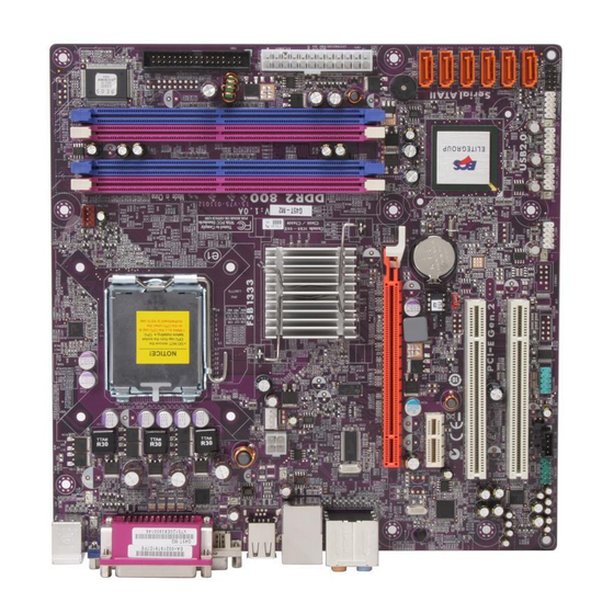
Page 9: Motherboard Components
Motherboard Components Table of Motherboard Components LABEL COMPONENTS ® LGA775 socket for Intel Yorkfield/Wolfdale/Core 2 Quad/ 1. CPU Socket ® Core 2 Duo/Pentium Dual-Core (E21XX series)/ ® ® Celeron Dual-Core/Celeron 4xx series CPUs 2. CPU_FAN CPU cooling fan connector 3. DIMM1~4 240-pin DDR2 SDRAM slots 4. - Page 10 Memo Introducing the Motherboard...
-
Page 11: Installing The Motherboard
Chapter 2 Installing the Motherboard Safety Precautions • Follow these safety precautions when installing the motherboard • Wear a grounding strap attached to a grounded device to avoid dam- age from static electricity • Discharge static electricity by touching the metal case of a safely grounded object before working on the motherboard •... -
Page 12: Checking Jumper Settings
Do not over-tighten the screws as this can stress the motherboard. Checking Jumper Settings This section explains how to set jumpers for correct configuration of the motherboard. Setting Jumpers Use the motherboard jumpers to set system configuration options. Jumpers with more than one pin are numbered. -
Page 13: Checking Jumper Settings
Checking Jumper Settings The following illustration shows the location of the motherboard jumpers. Pin 1 is labeled. Jumper Settings Type Setting (default) Jumper Description 1-2: NORMAL 2-3: CLEAR CLR_CMOS 3-pin CLEAR CMOS Before clearing the CMOS, CLR_CMOS make sure to turn off the system. -
Page 14: Installing Hardware
Installing Hardware Installing the Processor Caution: When installing a CPU heatsink and cooling fan make sure that you DO NOT scratch the motherboard or any of the surface- mount resistors with the clip of the cooling fan. If the clip of the cooling fan scrapes across the motherboard, you may cause serious damage to the motherboard or its components. -
Page 15: Cpu Installation Procedure
CPU Installation Procedure The following illustration shows CPU installation components. A. Read and follow the instructions shown on the sticker on the CPU cap. B. Unload the cap · Use thumb & forefinger to hold the lifting tab of the cap. ·... -
Page 16: Installing Memory Modules
Installing Memory Modules This motherboard accomodates four memory modules. It can support four 240-pin DDR2 800/667. The total memory capacity is 16 GB. DDR2 SDRAM memory module table Memory module Memory Bus DDR2 667 333 MHz DDR2 800 400 MHz You must install at least one module in any of the four slots. - Page 17 Table A: DDR2 (memory module) QVL (Qualified Vendor List) The following DDR2 800/667 memory modules and combination have been tested and qualified for use with this motherboard. Type Size Vendor Module Name Infineon HYS64T325001HU-3-A HYB18T256 256 MB Ramaxel 5NB31 D9DCG A-DATA AD29608A88-3EG A-DATA...
- Page 18 Type Size Vendor Module Name NCPT7AUDR-25M48 Kingston KHX6400D2ULK2/2G Kingston KVR800D2N5/1G 1 GB Ramaxel E5108AHSE-8E-E 0705098L1 Samsung ZCE7 K4T510830E Transcend TQ123PGF8T0709 UMAX U2S12D30TP-8E Aeneon AET03R25DC 0732 Aeneon AET860UD00-25DC08X Apacer AM4B5808CQJS8E 0747D DDR2 800 Apacer 78.A1GA0.9K4 A-DATA RED A-DATA M2OMI6H3J4720L1C5Z CORSAIR CM2X2048-6400C5 Micron 7QEIID9HNP 2 GB...
-
Page 19: Expansion Slots
Expansion Slots Installing Add-on Cards The slots on this motherboard are designed to hold expansion cards and connect them to the system bus. Expansion slots are a means of adding or enhancing the motherboard’s features and capabilities. With these efficient facilities, you can in- crease the motherboard’s capabilities by adding hardware that performs tasks that are not part of the basic system. - Page 20 Follow these instructions to install an add-on card: Remove a blanking plate from the system case corresponding to the slot you are going to use. Install the edge connector of the add-on card into the expansion slot. Ensure that the edge connector is correctly seated in the slot. Secure the metal bracket of the card to the system case with a screw.
-
Page 21: Connecting Optional Devices
Connecting Optional Devices Refer to the following for information on connecting the motherboard’s optional devices: F_AUDIO: Front Panel Audio header This header allows the user to install auxiliary front-oriented microphone and line- out ports for easier access. Signal Name Signal Name Signal Name Function PORT 1L... - Page 22 CD_IN: Analog Audio Input connector Signal Name Function CD_L CD In left channel Ground Ground CD_R CD In right channel F_USB1~4: Front Panel USB headers The motherboard has four USB ports installed on the rear edge I/O port array. Additionally, some computer cases have USB ports at the front of the case. If you have this kind of case, use auxiliary USB connector to connect the front-mounted ports to the motherboard.
- Page 23 COM1: Onboard serial port header Connect a serial port extension bracket to this header to add a second serial port to your system. Signal Name Function DCDB Data Carrier Detect SINB Serial Input SOUTB UART B Serial Output DTRB UART B Data Terminal Ready Ground DSRB Data Set Ready...
-
Page 24: Installing A Sata Hard Drive
Installing a SATA Hard Drive About SATA Connectors Your motherboard features six SATA connectors supporting a total of six drives. SATA refers to Serial ATA (Advanced Technology Attachment) is the standard inter- face for the IDE hard drives which are currently used in most PCs. These connectors are well designed and will only fit in one orientation. -
Page 25: Installing A Floppy Diskette Drive
Installing a Floppy Diskette Drive FDD1: Floppy Disk Connector Connect the single end of the floppy connector to the onboard floppy connector firstly, and then connect the remaining plugs on the other end to the floppy drive correspondingly. You must orient the cable connector so that the pin 1 (color) edge of the cable corresponds to the pin 1 of the I/O port connector. -
Page 26: Connecting I/O Devices
Connecting I/O Devices The backplane of the motherboard has the following I/O ports: PS2 Mouse Use the upper PS/2 port to connect a PS/2 pointing device. PS2 Keyboard Use the lower PS/2 port to connect a PS/2 keyboard. Parallel Port (LPT1) Use LPT to connect printers or other parallel communica (Optional) tions devices. -
Page 27: Connecting Case Components
Connecting Case Components After you have installed the motherboard into a case, you can begin connecting the motherboard components. Refer to the following: Connect the CPU cooling fan cable to CPU_FAN. Connect the system cooling fan connector to SYS_FAN. Connect the case switches and indicator LEDs to the F_PANEL. Connect the standard power supply connector to ATX_POWER1. -
Page 28: Atx 12V Power Connector
CPU_FANS/SYS_FAN: FAN Power Connector Signal Name Function System Ground Power +12V +12V Sense Sensor Users please note that the fan connector supports the CPU cooling fan of 1.1A ~ 2.2A (26.4W max) at +12V. ATX_ POWER1: ATX 24-pin Power Connector Signal Name Signal Name +3.3V... -
Page 29: Front Panel Header
Front Panel Header The front panel header (F_PANEL) provides a standard set of switch and LED headers commonly found on ATX or Micro ATX cases. Refer to the table below for information: Signal Function Signal Function HD_LED_P Hard disk LED(+) 2 FP PWR/SLP *MSG LED(+) HD_LED_N Hard disk LED(- ) FP PWR/SLP *MSG LED(-) - Page 30 Memo Installing the Motherboard...
-
Page 31: Using Bios
Chapter 3 Using BIOS About the Setup Utility The computer uses the latest “American Megatrends Inc.” BIOS with support for Windows Plug and Play. The CMOS chip on the motherboard contains the ROM setup instructions for configuring the motherboard BIOS. The BIOS (Basic Input and Output System) Setup Utility displays the system’s configuration status and provides you with options to set system parameters. -
Page 32: Resetting The Default Cmos Values
Press the delete key to access the BIOS Setup Utility. CMOS Setup Utility -- Copyright (C) 1985-2008, American Megatrends, Inc. Standard CMOS Setup Frequency/Voltage Control Advanced Setup Load Default Settings Advanced Chipset Setup Supervisor Password Integrated Peripherals User Password Power Management Setup Save &... -
Page 33: Using Bios
Using BIOS When you start the Setup Utility, the main menu appears. The main menu of the Setup Utility displays a list of the options that are available. A highlight indicates which option is currently selected. Use the cursor arrow keys to move the highlight to other options. -
Page 34: Standard Cmos Setup
For the purpose of better product maintenance, the manufacture reserves the right to change the BIOS items presented in this manual. The BIOS setup screens shown in this chapter are for reference only and may differ from the actual BIOS. Please visit the manufacture’s website for updated manual. - Page 35 Type (Auto) Use this item to configure the type of the IDE device that you specify. If the feature is enabled, it will enhance hard disk performance by reading or writing more data during each transfer. LBA/Large Mode (Auto) Use this item to set the LAB/Large mode to enhance hard disk performance by optimizing the area the hard disk is visited each time.
-
Page 36: Advanced Setup
Advanced Setup This page sets up more advanced information about your system. Handle this page with caution. Any changes can affect the operation of your computer. CMOS Setup Utility - Copyright (C) 1985-2008, American Megatrends, Inc. Advanced Setup Thermal Management Enabled Help Item TM Status... - Page 37 APIC Mode (Enabled) This item allows you to enable or disable the APCI (Advanced Programmable Inter- rupt Controller) mode. APIC provides symmetric multi-processing (SMP) for sys- tems, allowing support for up to 60 processors. 1st/2nd/3rd Boot Device (Hard Disk Drive/CD/DVD/1st FLOPPY DRIVE) Use this item to determine the device order the computer used to look for an operating system to load at start-up time.
-
Page 38: Advanced Chipset Setup
Advanced Chipset Setup This page sets up more advanced information about your system. Handle this page with caution. Any changes can affect the operation of your computer. CMOS Setup Utility - Copyright (C) 1985-2008, American Megatrends, Inc. Advanced Chipset Setup DRAM Frequency Auto Help Item... -
Page 39: Integrated Peripherals
Integrated Peripherals This page sets up some parameters for peripheral devices connected to the system. CMOS Setup Utility - Copyright (C) 1985-2008, American Megatrends, Inc. Integrated Peripherals Onboard SATA Mode Enhanced Help Item Onboard LAN Function Enabled Onboard LAN Boot ROM Disabled Options Onboard AUDIO Function... -
Page 40: Power Management Setup
Parallel Port IRQ (IRQ7) Use this item to assign IRQ to the parallel port. USB Functions (Enabled) Use this item to enable or disable the USB function. Legacy USB Support (Enabled) Use this item to enable or disable support for legacy USB devices. Setting to Auto allows the system to detect the presence of USB device at startup. -
Page 41: Pci/Pnp Setup
Resume by Ring (Disabled) An input signal on the serial Ring Indicator (RI) line (in other words, an incoming callon the modem) awakens the system from a soft off state. Resume by PCI/PCI-E/Lan PME (Disabled) These items specify whether the system will be awakened from power saving modeswhen activity or input signal of the specified hardware peripheral or compo- nent isdetected. -
Page 42: Pc Health Status
PC Health Status On motherboards support hardware monitoring, this item lets you monitor the parameters for critical voltages, temperatures and fan speeds. CMOS Setup Utility - Copyright (C) 1985-2008, American Megatrends, Inc. PC Health Status Help Item -=- System Hardware Monitor-=- Smart Fan Function Press Enter CPU Temperature... - Page 43 CPU Fan Full Limit Temp. (°C) (69°C) This item is used to set the limit temperature of the smart fan. ECS supports the latest PECI host technology. While using Wolfdale or Yorkfield CPU, the original images of the BIOS item “PC Health Status”...
-
Page 44: Frequency/Voltage Control
System Component Characteristics These items display the monitoring of the overall inboard hardware health events, such as System & CPU temperature, CPU & DIMM voltage, CPU & system fan speed,...etc. • CPU/System Temperature • CPU/SYS FAN Speed • CPU Core •... -
Page 45: Load Default Settings
CPU Over-clocking Func. (Disabled) This item decides the CPU over-clocking function/frequencyinstalled in your sys- tem. If the over-clocking fails, please turn offthe system power. And then, hold the PageUp key (similar to theClear CMOS function) and turn on the power, the BIOS willrecover the safe default. -
Page 46: User Password
User Password This page helps you install or change a password. CMOS Setup Utility - Copyright (C) 1985-2008, American Megatrends, Inc. User Password User Password : Not Installed Help item Change User Password Press Enter Install or Change the password. : Move Enter : Select +/-/: Value... -
Page 47: Updating The Bios
Updating the BIOS You can download and install updated BIOS for this motherboard from the manufacturer’s Web site. New BIOS provides support for new peripherals, improve- ments in performance, or fixes for known bugs. Install new BIOS as follows: If your motherboard has a BIOS protection jumper, change the setting to allow BIOS flashing. - Page 48 Memo Using BIOS...
-
Page 49: Using The Motherboard Software
Chapter 4 Using the Motherboard Software About the Software DVD-ROM/CD-ROM The support software DVD-ROM/CD-ROM that is included in the motherboard package contains all the drivers and utility programs needed to properly run the bundled products. Below you can find a brief description of each software program, and the location for your motherboard version. -
Page 50: Running Setup
Drivers Tab Setup Click the Setup button to run the software installation program. Select from the menu which software you want to install. Browse CD The Browse CD button is the standard Windows command that allows you to open Windows Explorer and show the contents of the support disk. - Page 51 Click Next. The following screen appears: Check the box next to the items you want to install. The default options are recom- mended. Click Next run the Installation Wizard. An item installation screen appears: Follow the instructions on the screen to install the items. Drivers and software are automatically installed in sequence.
-
Page 52: Manual Installation
Windows Vista/7 will appear below UAC (User Account Control) message after the system restart. You must select “Allow” to install the next driver. Continue this process to complete the drivers installation. Manual Installation Insert the disk in the DVD-ROM/CD-ROM drive and locate the PATH.DOC file in the root directory. -
Page 53: Hdmi Audio Setting Sop
HDMI Audio Setting SOP OS: XP system 1. Control Panel-->Sound and Audio Device Properties a. Audio--> Sound playback--> Default device--> HD Auido Output b. Audio--> Sound playback--> Default device--> HDMI Auido Output a. User Playback Audio speaker function working b. User Playback HDMI speaker function working Using the Motherboard Software... - Page 54 OS: Vista system Control Panel--> Soundback--> Sound--> Digital Output Device (HDMI) --> Set Default 1. Volume --> Playback 2. Digital Output Device (HDMI) --> Set Default --> OK User HDMI Playback function working Using the Motherboard Software...
- Page 55 3. Speaker --> Set Default --> OK User Speaker Palyback function working 4. SPDIF-Out --> Set Default --> OK User SPDIF-Out Playback function working This concludes chapter 4. Using the Motherboard Software...
- Page 56 Memo Using the Motherboard Software...
-
Page 57: Trouble Shooting
Chapter 5 Trouble Shooting Start up problems during assembly After assembling the PC for the first time you may experience some start up problems. Before calling for technical support or returning for warranty, this chapter may help to address some of the common questions using some basic troubleshooting tips. -
Page 58: Start Up Problems After Prolong Use
c) The PC suddenly shuts down while booting up. 1. The CPU may experience overheating so it will shutdown to protect itself. Ensure the CPU fan is working properly. 2. From the BIOS setting, try to disable the Smartfan function to let the fan run at default speed. - Page 60 Memo Trouble Shooting...