Table of Contents
Advertisement
Advertisement
Table of Contents

Related Manuals for Asus P5P800-MX


Summary of Contents for Asus P5P800-MX
- Page 1 P5P800-MX...
- Page 2 Product warranty or service will not be extended if: (1) the product is repaired, modified or altered, unless such repair, modification of alteration is authorized in writing by ASUS; or (2) the serial number of the product is defaced or missing.
-
Page 3: Table Of Contents
Welcome! ................1-2 Package contents ..............1-2 Special features ..............1-2 1.3.1 Product highlights ........... 1-2 1.3.2 Innovative ASUS features ........1-4 Before you proceed .............. 1-5 Motherboard overview ............1-6 1.5.1 Placement direction ..........1-6 1.5.2 Screw holes ............1-6 1.5.3... - Page 4 Creating a bootable floppy disk ......2-2 2.1.2 ASUS EZ Flash utility ..........2-3 2.1.3 AFUDOS utility ............2-4 2.1.4 ASUS CrashFree BIOS 2 utility ........ 2-6 2.1.5 ASUS Update utility ..........2-8 BIOS setup program ............2-11 2.2.1 BIOS menu screen ..........2-12 2.2.2...
- Page 5 Chapter 3: Software support Installing an operating system ..........3-2 Support CD information ............3-2 3.2.1 Running the support CD ......... 3-2 3.2.2 Drivers menu ............3-3 3.2.3 Utilities menu ............3-4 3.2.4 ASUS Contact information ........3-5 v v v v v...
-
Page 6: Notices
Notices Federal Communications Commission Statement Federal Communications Commission Statement Federal Communications Commission Statement Federal Communications Commission Statement Federal Communications Commission Statement This device complies with Part 15 of the FCC Rules. Operation is subject to the following two conditions: • This device may not cause harmful interference, and •... -
Page 7: Safety Information
Safety information Electrical safety Electrical safety Electrical safety Electrical safety Electrical safety • To prevent electrical shock hazard, disconnect the power cable from the electrical outlet before relocating the system. • When adding or removing devices to or from the system, ensure that the power cables for the devices are unplugged before the signal cables are connected. -
Page 8: About This Guide
A S U S w e b s i t e s A S U S w e b s i t e s The ASUS website provides updated information on ASUS hardware and software products. Refer to the ASUS contact information. -
Page 9: Conventions Used In This Guide
Conventions used in this guide Conventions used in this guide Conventions used in this guide Conventions used in this guide Conventions used in this guide To make sure that you perform certain tasks properly, take note of the following symbols used throughout this manual. D A N G E R / W A R N I N G : D A N G E R / W A R N I N G : D A N G E R / W A R N I N G :... -
Page 10: P5P800-Mx Specifications Summary
S p e c i a l f e a t u r e s S p e c i a l f e a t u r e s ASUS Q-Fan ASUS Instant Music Lite ASUS EZ Flash ASUS CrashFree BIOS 2 ASUS MyLogo2™... - Page 11 B I O S f e a t u r e s 4 Mb Flash ROM, AMI BIOS, PnP, WfM2.0, DMI2.0, SM BIOS 2.3, ASUS EZ Flash, CrashFree BIOS2, C.P.R. (CPU Parameter Recall), ASUS MyLogo2 I n d u s t r y s t a n d a r d...
- Page 12 x i i x i i x i i x i i x i i...
-
Page 13: Chapter 1: Product Introduction
This chapter describes the motherboard features and the new technologies it supports. Product introduction A S U S P 5 P 8 0 0 - M X A S U S P 5 P 8 0 0 - M X A S U S P 5 P 8 0 0 - M X 1 - 1 1 - 1... -
Page 14: Welcome
P 5 P 8 0 0 - M X m o t h e r b o a r d ! The motherboard delivers a host of new features and latest technologies, making it another standout in the long line of ASUS quality motherboards! Before you start installing the motherboard, and hardware devices on it, check the items in your package with the list below. - Page 15 Intel Intel Intel ® ® ® ® ® Extreme Graphics support Extreme Graphics support Extreme Graphics support Intel Intel Extreme Graphics support Extreme Graphics support The motherboard supports the Intel ® Extreme Graphics technology through the Intel ® 865GV chipset that delivers powerful integrated 2D and 3D graphics.
-
Page 16: Innovative Asus Features
ASUS EZ Flash BIOS ASUS EZ Flash BIOS With the ASUS EZ Flash, you can easily update the system BIOS even before loading the operating system. No need to use a DOS-based utility or boot from a floppy disk. See page 2-3 for details. -
Page 17: Before You Proceed
Before you proceed Take note of the following precautions before you install motherboard components or change any motherboard settings. • Unplug the power cord from the wall socket before touching any component. • Use a grounded wrist strap or touch a safely grounded object or to a metal object, such as the power supply case, before handling components to avoid damaging them due to static electricity •... -
Page 18: Motherboard Overview
Motherboard overview Before you install the motherboard, study the configuration of your chassis to ensure that the motherboard fits into it. Make sure to unplug the power cord before installing or removing the motherboard. Failure to do so can cause you physical injury and damage motherboard components. -
Page 19: Motherboard Layout
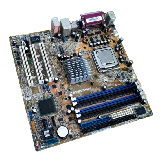
1.5.3 1.5.3 1.5.3 1.5.3 1.5.3 Motherboard layout Motherboard layout Motherboard layout Motherboard layout Motherboard layout 24.5cm (9.6in) PS/2KBMS KBPWR1 CHA_FAN1 T: Mouse B: Keyboard ATX12V1 COM1 LGA775 CPU_FAN1 VGA1 USB2.0_1.2 Intel USB2.0 Top: T: USB4 RJ-45 865GV B: USB3 USBPW12 USBPW34 GMCH Top:Line In... -
Page 20: Central Processing Unit (Cpu)
Contact your retailer immediately if the PnP cap is missing, or if you see any damage to the PnP cap/socket pins/motherboard components. ASUS will shoulder the cost of repair only if the damage is shipment/ transit-related. •... - Page 21 Press the load lever with your thumb (A) and move it to the left (B) until it is released from the retention tab. P n P C a p P n P C a p P n P C a p P n P C a p P n P C a p R e t e n t i o n t a b...
- Page 22 Close the load plate (A), then push the load lever (B) until it snaps into the retention tab. The CPU fits in only one correct orientation. DO NOT force the CPU into the socket to prevent bending the connectors on the socket and damaging the CPU! Notes on Intel Notes on Intel...
-
Page 23: Installling The Cpu Heatsink And Fan
1.6.2 1.6.2 1.6.2 Installling the CPU heatsink and fan Installling the CPU heatsink and fan Installling the CPU heatsink and fan 1.6.2 1.6.2 Installling the CPU heatsink and fan Installling the CPU heatsink and fan The Intel ® Pentium ® 4 LGA775 processor requires a specially designed heatsink and fan assembly to ensure optimum thermal condition and performance. - Page 24 Push down two fasteners at a time in a diagonal sequence to secure the heatsink and fan assembly in place. Connect the CPU fan cable to the connector on the motherboard labeled CPU_FAN1. CPU_FAN1 CPU FAN PWM CPU FAN IN CPU FAN PWR ®...
-
Page 25: Uninstalling The Cpu Heatsink And Fan
1.6.3 1.6.3 1.6.3 Uninstalling the CPU heatsink and fan Uninstalling the CPU heatsink and fan Uninstalling the CPU heatsink and fan 1.6.3 1.6.3 Uninstalling the CPU heatsink and fan Uninstalling the CPU heatsink and fan To uninstall the CPU heatsink and fan: Disconnect the CPU fan cable from the connector on the motherboard. - Page 26 Carefully remove the heatsink and fan assembly from the motherboard. Rotate each fastener clockwise to ensure correct orientation when reinstalling. N a r r o w e n d o f t h e g r o o v e N a r r o w e n d o f t h e g r o o v e N a r r o w e n d o f t h e g r o o v e N a r r o w e n d o f t h e g r o o v e...
-
Page 27: System Memory
DDR Qualified Vendors List DDR Qualified Vendors List The following table lists the memory modules that have been tested and qualified for use with this motherboard. Visit the ASUS website (www.asus.com) for the latest DDR DIMM modules for this motherboard. Table 1... - Page 28 Table 1 Table 1 DDR Qualified Vendors List DDR Qualified Vendors List Table 1 Table 1 Table 1 DDR Qualified Vendors List DDR Qualified Vendors List DDR Qualified Vendors List DIMM support S i z e S i z e S i z e S i z e S i z e...
-
Page 29: Installing A Dimm
1.7.3 1.7.3 1.7.3 Installing a DIMM Installing a DIMM Installing a DIMM 1.7.3 1.7.3 Installing a DIMM Installing a DIMM Make sure to unplug the power supply before adding or removing DIMMs or other system components. Failure to do so may cause severe damage to both the motherboard and the components. -
Page 30: Expansion Slots
Expansion slots In the future, you may need to install expansion cards. The following sub-sections describe the slots and the expansion cards that they support. Make sure to unplug the power cord before adding or removing expansion cards. Failure to do so may cause you physical injury and damage motherboard components. -
Page 31: Interrupt Assignments
1.8.3 1.8.3 1.8.3 1.8.3 1.8.3 Interrupt assignments Interrupt assignments Interrupt assignments Interrupt assignments Interrupt assignments Standard interrupt assignments Standard interrupt assignments Standard interrupt assignments Standard interrupt assignments Standard interrupt assignments I R Q I R Q I R Q P r i o r i t y P r i o r i t y P r i o r i t y S t a n d a r d F u n c t i o n... -
Page 32: Pci Slots
1.8.4 1.8.4 1.8.4 PCI slots PCI slots PCI slots 1.8.4 1.8.4 PCI slots PCI slots The PCI slots support cards such as a LAN card, SCSI card, USB card, and other cards that comply with PCI specifications. The figure shows a LAN card installed on a PCI slot. -
Page 33: Jumpers
Jumpers 1 . 1 . C l e a r R T C R A M ( 3 - p i n C L R T C 1 ) C l e a r R T C R A M ( 3 - p i n C L R T C 1 ) C l e a r R T C R A M ( 3 - p i n C L R T C 1 ) C l e a r R T C R A M ( 3 - p i n C L R T C 1 ) C l e a r R T C R A M ( 3 - p i n C L R T C 1 ) - Page 34 2 . 2 . U S B d e v i c e w a k e - u p ( 3 - p i n U S B P W 1 2 , U S B P W 3 4 , U S B d e v i c e w a k e - u p ( 3 - p i n U S B P W 1 2 , U S B P W 3 4 , U S B d e v i c e w a k e - u p ( 3 - p i n U S B P W 1 2 , U S B P W 3 4 , U S B d e v i c e w a k e - u p ( 3 - p i n U S B P W 1 2 , U S B P W 3 4 ,...
-
Page 35: 1.10 Connectors
3 . 3 . K e y b o a r d p o w e r ( 3 - p i n K B P W R 1 ) K e y b o a r d p o w e r ( 3 - p i n K B P W R 1 ) K e y b o a r d p o w e r ( 3 - p i n K B P W R 1 ) K e y b o a r d p o w e r ( 3 - p i n K B P W R 1 ) K e y b o a r d p o w e r ( 3 - p i n K B P W R 1 ) - Page 36 3 . 3 . L A N ( R J - 4 5 ) p o r t . L A N ( R J - 4 5 ) p o r t . L A N ( R J - 4 5 ) p o r t . L A N ( R J - 4 5 ) p o r t .
-
Page 37: Internal Connectors
1.10.2 1.10.2 Internal connectors 1.10.2 Internal connectors Internal connectors Internal connectors 1.10.2 1.10.2 Internal connectors 1 . 1 . F l o p p y d i s k d r i v e c o n n e c t o r ( 3 4 - 1 p i n F L O P P Y 1 ) F l o p p y d i s k d r i v e c o n n e c t o r ( 3 4 - 1 p i n F L O P P Y 1 ) F l o p p y d i s k d r i v e c o n n e c t o r ( 3 4 - 1 p i n F L O P P Y 1 ) F l o p p y d i s k d r i v e c o n n e c t o r ( 3 4 - 1 p i n F L O P P Y 1 ) -
Page 38: Hard Disk Drives
3 . 3 . S e r i a l A T A c o n n e c t o r s ( 7 - p i n S A T A 1 , S A T A 2 ) S e r i a l A T A c o n n e c t o r s ( 7 - p i n S A T A 1 , S A T A 2 ) S e r i a l A T A c o n n e c t o r s ( 7 - p i n S A T A 1 , S A T A 2 ) S e r i a l A T A c o n n e c t o r s ( 7 - p i n S A T A 1 , S A T A 2 ) - Page 39 5 . 5 . D i g i t a l A u d i o c o n n e c t o r ( 4 - 1 p i n S P D I F _ O U T 1 ) D i g i t a l A u d i o c o n n e c t o r ( 4 - 1 p i n S P D I F _ O U T 1 ) D i g i t a l A u d i o c o n n e c t o r ( 4 - 1 p i n S P D I F _ O U T 1 ) D i g i t a l A u d i o c o n n e c t o r ( 4 - 1 p i n S P D I F _ O U T 1 )
- Page 40 7 . 7 . F r o n t p a n e l a u d i o c o n n e c t o r ( 1 0 - 1 p i n F P _ A U D I O 1 ) F r o n t p a n e l a u d i o c o n n e c t o r ( 1 0 - 1 p i n F P _ A U D I O 1 ) F r o n t p a n e l a u d i o c o n n e c t o r ( 1 0 - 1 p i n F P _ A U D I O 1 ) F r o n t p a n e l a u d i o c o n n e c t o r ( 1 0 - 1 p i n F P _ A U D I O 1 )
- Page 41 9 . 9 . I n t e r n a l a u d i o c o n n e c t o r s ( 4 - p i n C D 1 , A U X 1 ) I n t e r n a l a u d i o c o n n e c t o r s ( 4 - p i n C D 1 , A U X 1 ) I n t e r n a l a u d i o c o n n e c t o r s ( 4 - p i n C D 1 , A U X 1 ) I n t e r n a l a u d i o c o n n e c t o r s ( 4 - p i n C D 1 , A U X 1 )
-
Page 42: System Panel Connector
1 1 . 1 1 . 1 1 . 1 1 . 1 1 . S y s t e m p a n e l c o n n e c t o r ( 2 0 - 1 p i n P A N E L ) S y s t e m p a n e l c o n n e c t o r ( 2 0 - 1 p i n P A N E L ) S y s t e m p a n e l c o n n e c t o r ( 2 0 - 1 p i n P A N E L ) S y s t e m p a n e l c o n n e c t o r ( 2 0 - 1 p i n P A N E L ) -
Page 43: Chapter 2: Bios Setup
This chapter tells how to change the system settings through the BIOS Setup menus. Detailed descriptions of the BIOS parameters are also provided. BIOS setup A S U S P 5 P 8 0 0 - M X A S U S P 5 P 8 0 0 - M X A S U S P 5 P 8 0 0 - M X 2 - 1 2 - 1... -
Page 44: Managing And Updating Your Bios
Refer to the corresponding sections for details on these utilities. Save a copy of the original motherboard BIOS file to a bootable floppy disk in case you need to restore the BIOS in the future. Copy the original motherboard BIOS using the ASUS Update or AFUDOS utilities. 2.1.1 2.1.1 2.1.1... -
Page 45: Asus Ez Flash Utility
ASUS EZ Flash utility ASUS EZ Flash utility The ASUS EZ Flash feature allows you to update the BIOS without having to go through the long process of booting from a floppy disk and using a DOS-based utility. The EZ Flash utility is built-in the BIOS chip so it is accessible by pressing <Alt>... -
Page 46: Afudos Utility
2.1.3 2.1.3 2.1.3 AFUDOS utility AFUDOS utility AFUDOS utility 2.1.3 2.1.3 AFUDOS utility AFUDOS utility The AFUDOS utility allows you to update the BIOS file in DOS environment using a bootable floppy disk with the updated BIOS file. This utility also allows you to copy the current BIOS file that you can use as backup when the BIOS fails or gets corrupted during the updating process. - Page 47 Updating the BIOS file To update the BIOS file using the AFUDOS utility: Visit the ASUS website (www.asus.com) and download the latest BIOS file for the motherboard. Save the BIOS file to a bootable floppy disk. Write the BIOS filename on a piece of paper. You need to type the exact BIOS filename at the DOS prompt.
-
Page 48: Asus Crashfree Bios 2 Utility
ASUS CrashFree BIOS 2 utility ASUS CrashFree BIOS 2 utility The ASUS CrashFree BIOS 2 is an auto recovery tool that allows you to restore the BIOS file when it fails or gets corrupted during the updating process. You can update a corrupted BIOS file using the motherboard support CD or the floppy disk that contains the updated BIOS file. - Page 49 Restart the system after the utility completes the updating process. The recovered BIOS may not be the latest BIOS version for this motherboard. Visit the ASUS website (www.asus.com) to download the latest BIOS file. A S U S P 5 P 8 0 0 - M X...
-
Page 50: Asus Update Utility
ASUS Update utility 2.1.5 2.1.5 ASUS Update utility ASUS Update utility The ASUS Update is a utility that allows you to manage, save, and update the motherboard BIOS in Windows ® environment. The ASUS Update utility allows you to: • Save the current BIOS file •... - Page 51 Updating the BIOS through the Internet Updating the BIOS through the Internet Updating the BIOS through the Internet To update the BIOS through the Internet: Launch the ASUS Update utility from the Windows ® desktop by clicking S t a r t...
- Page 52 A S U S U p d a t e A S U S U p d a t e. The ASUS Update main window appears. U p d a t e B I O S f r o m a...
-
Page 53: Bios Setup Program
• Visit the ASUS website (www.asus.com) to download the latest BIOS file for this motherboard and . A S U S P 5 P 8 0 0 - M X... -
Page 54: Bios Menu Screen
2.2.1 2.2.1 2.2.1 BIOS menu screen BIOS menu screen BIOS menu screen 2.2.1 2.2.1 BIOS menu screen BIOS menu screen M e n u i t e m s M e n u i t e m s M e n u i t e m s M e n u i t e m s M e n u i t e m s M e n u b a r... -
Page 55: Menu Items
For example, selecting M a i n M a i n M a i n shows the Primary IDE Master :[ST320413A] configure system time. Primary IDE Slave :[ASUS CD-S340] Secondary IDE Master :[Not Detected] Secondary IDE Slave :[Not Detected] Main menu items. Third IDE Master... -
Page 56: Main Menu
Main menu When you enter the BIOS Setup program, the Main menu screen appears, giving you an overview of the basic system information. Refer to section “2.2.1 BIOS menu screen” for information on the menu screen items and how to navigate through them. System Time [11:51:19] Use [ENTER], [TAB]... -
Page 57: Primary, Third And Fourth Ide Master/Slave
2.3.4 2.3.4 2.3.4 Primary, Secondary, Third and Fourth IDE Primary, Secondary, Third and Fourth IDE Primary, Secondary, Third and Fourth IDE 2.3.4 2.3.4 Primary, Secondary, Third and Fourth IDE Primary, Secondary, Third and Fourth IDE Master/Slave Master/Slave Master/Slave Master/Slave Master/Slave While entering Setup, the BIOS automatically detects the presence of IDE devices. -
Page 58: Ide Configuration
PIO Mode [Auto] PIO Mode [Auto] PIO Mode [Auto] PIO Mode [Auto] PIO Mode [Auto] Selects the PIO mode. Configuration options: [Auto] [0] [1] [2] [3] [4] DMA Mode [Auto] DMA Mode [Auto] DMA Mode [Auto] DMA Mode [Auto] DMA Mode [Auto] Selects the DMA mode. -
Page 59: System Information
The P-ATA+S-ATA and P-ATA options are for advanced users only. If you set to any of these options and encounter problems, revert to the default setting S - A T A S - A T A S - A T A S - A T A. -
Page 60: Advanced Menu
Advanced menu The Advanced menu items allow you to change the settings for the CPU and other system devices. Take caution when changing the settings of the Advanced menu items. Incorrect field values can cause the system to malfunction. Instant Music Configuration CPU Configuration Chipset Onboard Devices Configuration... -
Page 61: Cpu Configuration
2.4.2 2.4.2 2.4.2 CPU Configuration CPU Configuration CPU Configuration 2.4.2 2.4.2 CPU Configuration CPU Configuration The items in this menu show the CPU-related information that the BIOS automatically detects. Configure Advanced CPU settings Unlock locked CPU and let it run at Manufacturer: Intel lower multiplier Brand String: Intel(R) Pentium(R) 4 CPU 3.40GHz... -
Page 62: Chipset
Enhanced C1 Control [Auto] Enhanced C1 Control [Auto] Enhanced C1 Control [Auto] Enhanced C1 Control [Auto] Enhanced C1 Control [Auto] When set to [Auto], the BIOS will automatically check the CPU’s capability to enable the C1E support. In C1E mode, the CPU power consumption is lower when idle. - Page 63 DRAM RAS# Precharge [4 Clocks] Controls the idle clocks after issuing a precharge command to the DDR SDRAM. Configuration options: [4 Clocks] [3 Clocks] [2 Clocks] DRAM RAS# to CAS# Delay [4 Clocks] Controls the latency between the DDR SDRAM active command and the read/write command.
-
Page 64: Onboard Devices Configuration
2.4.4 2.4.4 2.4.4 Onboard Devices Configuration Onboard Devices Configuration Onboard Devices Configuration 2.4.4 2.4.4 Onboard Devices Configuration Onboard Devices Configuration Onboard AC’97 Audio [Auto] Onboard LAN [Enabled] Onboard LAN Boot ROM [Disabled] Serial Port1 Address [3F8/IRQ4] Serial Port2 Address [2F8/IRQ3] Parallel Port Address [378] Parallel Port Mode... -
Page 65: Pci Pnp
E P P V e r s i o n [ 1 . 9 ] E P P V e r s i o n [ 1 . 9 ] E P P V e r s i o n [ 1 . 9 ] E P P V e r s i o n [ 1 . - Page 66 Plug and Play O/S [No] Plug and Play O/S [No] Plug and Play O/S [No] Plug and Play O/S [No] Plug and Play O/S [No] When set to [No], BIOS configures all the devices in the system. When set to [Yes] and if you install a Plug and Play operating system, the operating system configures the Plug and Play devices not required for boot.
-
Page 67: Usb Configuration
2.4.6 2.4.6 USB Configuration USB Configuration 2.4.6 2.4.6 2.4.6 USB Configuration USB Configuration USB Configuration The items in this menu allows you to change the USB-related features. Select an item then press <Enter> to display the configuration options. USB Configuration Module Version - 2.23.2-5.3 USB Devices Enabled: None USB Function... - Page 68 USB Mass Storage Device Configuration USB Mass Storage Device Configuration USB Mass Storage Device Configuration USB Mass Storage Device Configuration USB Mass Storage Device Configuration USB Mass Storage Device Configuration USB Mass Storage Reset Delay [20 Sec] No USB Mass Storage device detected USB Mass Storage Reset Delay [20 Sec] Allows you to select the number of seconds POST waits for the USB mass storage device after the start unit command.
-
Page 69: Power Menu
Power menu The Power menu items allow you to change the settings for the Advanced Power Management (APM). Select an item then press <Enter> to display the configuration options. Suspend Mode [Auto] Repost Video on S3 Resume [No] ACPI 2.0 Support [No] ACPI APIC Support [Enabled]... -
Page 70: Apm Configuration
2.5.5 2.5.5 2.5.5 APM Configuration APM Configuration APM Configuration 2.5.5 2.5.5 APM Configuration APM Configuration APM Configuration Restore on AC Power Loss [Power Off] Power On By RTC Alarm [Disabled] Power On By External Modems [Disabled] Power On By PCI Devices [Disabled] Power On By PS/2 Keyboard [Disabled]... -
Page 71: Hardware Monitor
CPU Q-Fan Control [Disabled] CPU Q-Fan Control [Disabled] CPU Q-Fan Control [Disabled] Allows you to enable or disable the ASUS Q-Fan feature that smartly adjusts the fan speeds for more efficient system operation. Configuration options: [Disabled] [Enabled] The C P U Q - F a n M o d e... - Page 72 CPU Q-Fan Mode [PWM] CPU Q-Fan Mode [PWM] CPU Q-Fan Mode [PWM] CPU Q-Fan Mode [PWM] CPU Q-Fan Mode [PWM] Allows you to select the type of CPU fan cable connected to the CPU fan connector. Set to [PWM] when using a 4-pin CPU fan cable. Set to [DC] when using a 3-pin CPU fan cable.
-
Page 73: Boot Menu
[1st FLOPPY DRIVE] 2nd Boot Device [PM-ST330620A] 3rd Boot Device [PS-ASUS CD-S360] 1st ~ xxth Boot Device [1st Floppy Drive] 1st ~ xxth Boot Device [1st Floppy Drive] 1st ~ xxth Boot Device [1st Floppy Drive] 1st ~ xxth Boot Device [1st Floppy Drive]... -
Page 74: Boot Settings Configuration
This allows you to enable or disable the full screen logo display feature. Configuration options: [Disabled] [Enabled] Set this item to [Enabled] to use the ASUS MyLogo2™ feature. Add On ROM Display Mode [Force BIOS] Add On ROM Display Mode [Force BIOS]... -
Page 75: Security
Interrupt 19 Capture [Disabled] Interrupt 19 Capture [Disabled] Interrupt 19 Capture [Disabled] Interrupt 19 Capture [Disabled] Interrupt 19 Capture [Disabled] When set to [Enabled], this function allows the option ROMs to trap Interrupt 19. Configuration options: [Disabled] [Enabled] 2.6.3 2.6.3 2.6.3 2.6.3 2.6.3... - Page 76 After you have set a supervisor password, the other items appear to allow you to change other security settings. Security Settings Supervisor Password : Not Installed User Password : Not Installed Change Supervisor Password User Access Level [Full Access] Change User Password Clear User Password Password Check [Setup]...
- Page 77 Clear User Password Clear User Password Clear User Password Clear User Password Clear User Password Select this item to clear the user password. Password Check [Setup] Password Check [Setup] Password Check [Setup] Password Check [Setup] Password Check [Setup] When set to [Setup], BIOS checks for user password when accessing the Setup utility.
-
Page 78: Exit Menu
Exit menu The Exit menu items allow you to load the optimal or failsafe default values for the BIOS items, and save or discard your changes to the BIOS items. Exit Options Exit system setup after saving the Exit & Save Changes changes. -
Page 79: Chapter 3: Software Support
This chapter describes the contents of the support CD that comes with the motherboard package. Software support A S U S P 5 P 8 0 0 - M X A S U S P 5 P 8 0 0 - M X A S U S P 5 P 8 0 0 - M X 3 - 1 3 - 1... -
Page 80: Installing An Operating System
The support CD that came with the motherboard package contains the drivers, software applications, and utilities that you can install to avail all motherboard features. The contents of the support CD are subject to change at any time without notice. Visit the ASUS website(www.asus.com) for updates. 3.2.1 3.2.1 3.2.1... -
Page 81: Drivers Menu
3.2.2 3.2.2 3.2.2 3.2.2 3.2.2 Drivers menu Drivers menu Drivers menu Drivers menu Drivers menu The drivers menu shows the available device drivers if the system detects installed devices. Install the necessary drivers to activate the devices. Intel(R) Chipset Inf Update Program Intel(R) Chipset Inf Update Program Intel(R) Chipset Inf Update Program Intel(R) Chipset Inf Update Program... -
Page 82: Utilities Menu
ASUS Update ASUS Update ASUS Update ASUS Update The ASUS Update utility allows you to update the motherboard BIOS in a Windows ® environment. This utility requires an Internet connection either through a network or an Internet Service Provider (ISP). See page 2-8 for details. -
Page 83: Asus Contact Information
C o n t a c t C o n t a c t C o n t a c t tab to display the ASUS contact information. You can C o n t a c t also find this information on the inside front cover of this user guide. - Page 84 3 - 6 3 - 6 3 - 6 C h a p t e r 3 : S o f t w a r e s u p p o r t C h a p t e r 3 : S o f t w a r e s u p p o r t C h a p t e r 3 : S o f t w a r e s u p p o r t 3 - 6 3 - 6...