Table of Contents
Advertisement
Quick Links
Advertisement
Table of Contents

Related Manuals for Asus A7V266-MX


Summary of Contents for Asus A7V266-MX
- Page 1 A7V266-MX User Guide...
- Page 2 Product warranty or service will not be extended if: (1) the product is repaired, modified or altered, unless such repair, modification of alteration is authorized in writing by ASUS; or (2) the serial number of the product is defaced or missing.
-
Page 3: Table Of Contents
Contents ..................... iii Notices ......................v Safety information ..................vi A7V266-MX specification summary ............vii Chapter 1: Product introduction Welcome! ..................1-2 Package contents ................1-2 Special features ................1-2 Motherboard components .............. 1-4 Motherboard layout ................ 1-7 Motherboard installation ..............1-8 1.6.1 Placement direction ............ - Page 4 Exit Menu ..................2-28 Chapter 3: Software support Installing an operating system ............3-2 Support CD information ..............3-2 3.2.1 Running the support CD ..........3-2 3.2.2 Drivers menu ..............3-3 3.2.3 Utilities menu ..............3-4 3.2.4 ASUS contact information ..........3-5...
-
Page 5: Federal Communications Commission Statement
Federal Communications Commission Statement This device complies with FCC Rules Part 15. Operation is subject to the following two conditions: • This device may not cause harmful interference, and • This device must accept any interference received including interference that may cause undesired operation. This equipment has been tested and found to comply with the limits for a Class B digital device, pursuant to Part 15 of the FCC Rules. -
Page 6: Electrical Safety
Electrical safety • To prevent electrical shock hazard, disconnect the power cable from the electrical outlet before relocating the system. • When adding or removing devices to or from the system, ensure that the power cables for the devices are unplugged before the signal cables are connected. - Page 7 CD / AUX connectors S/PDIF out connector GAME/MIDI connector Front panel audio connector BIOS features 2Mb Flash ROM, Award BIOS, ACPI, DMI2.0, WfM 2.0, SMBIOS 2.3, PnP features, TCAV, ASUS EZ Flash, CrashFree BIOS, ASUS C.O.P. (CPU Overheating Protection) (continued next page)
-
Page 8: Contents
Direct X Adobe Acrobat Reader ™ Trend Micro PC-cillin 2002 Accessories User Guide ASUS A7V266-MX support CD UltraATA cable FDD cable I/O shield Form factor Micro-ATX form factor: 9.6 in x 9.6 in * Specifications are subject to change without notice. -
Page 9: Chapter 1: Product Introduction
This chapter describes the features of this motherboard. It includes brief descriptions of the motherboard components, and illustrations of the layout, jumper settings, and connectors. Product introduction... -
Page 10: Integrated Graphics
Check your ASUS A7V266-MX package for the following items. ASUS A7V266-MX motherboard. (Micro-ATX form factor: 9.6 in x 9.6 in) ASUS A7V266-MX support CD 40-pin 80-conductor ribbon cable for UltraDMA133 IDE drives Ribbon cable for a 3.5-inch floppy drive... -
Page 11: Asus Crashfree Bios
1.1 to a fast 480 Mbps on USB 2.0. USB 2.0 is backward compatible with USB 1.1. ASUS C.O.P. The ASUS C.O.P. (CPU Overheating Protection) is a hardware protection circuit that automatically shuts down the system power before temperatures go high enough to permanently damage the CPU. - Page 12 Before you install the motherboard, learn about its major components and available features to facilitate the installation and future upgrades. Refer to the succeeding pages for the component descriptions. Chapter 1: Product introduction...
- Page 13 PS/2 mouse. Onboard LED. This onboard LED lights up if there is a standby power on the motherboard. This LED acts as a reminder to turn off the system power before plugging or unplugging devices. ASUS A7V266-MX motherboard user guide...
- Page 14 Southbridge. The VIA VT8235 CE Southbridge controller communicates with the north bridge at rates of up to 533MB/s using the VIA 8X VLink Technology. The Southbridge controller provides efficient bandwith requirements for PCI, USB and support for LAN devices. The controller also supports standard UltraDMA133/100/66 and provides separate data paths for each IDE channel for up to two IDE devices.
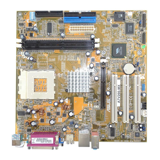
- Page 15 Center:Line Out Below:Mic In Accelerated Graphics Port (AGP1) ® PCI1 VT6103 A7V266-MX VT8235CE PCI2 CHA_FAN1 CR2032 3V Super Lithium Cell CMOS Power SPDIF PCI3 AD1980 CLRTC CODEC CHASSIS USBPWR56 USB56 FP_AUDIO AUX1 SB_PWR GAME PANEL ASUS A7V266-MX motherboard user guide...
-
Page 16: Motherboard Components
The A7V266-MX uses the Micro ATX form factor, measuring 24.5 cm (9.6 in.) x 24.5 cm (9.6 in.) - a standard fit for most large chassis. Unplug the power cord before installing the motherboard. Failure to do so may cause you physical injury and damage Motherboard components. 1.6.1 Placement direction Orient the motherboard with the chassis before installation. - Page 17 When lit, the onboard LED indicates that the system is ON, in sleep mode or in soft-off mode, not powered OFF. See the illustration below. SB_PWR ® A7V266-MX Standby Powered A7V266-MX Onboard LED Power ASUS A7V266-MX motherboard user guide...
-
Page 18: Installing The Cpu
The motherboard provides a Socket A (462) for CPU installation. The A7V266-MX supports Athlon™ XP processors with “QuantiSpeed” data processing, large data caches, 3D enhancements and 266/200MHz bus speeds. AMD Athlon™ XP processors offer gigahertz speeds to support all the latest computing platforms and applications CPU NOTCH TO INNER... -
Page 19: Installing A Dimm
A DDR DIMM is keyed with a notch so that it fits in only one direction. DO NOT force a DIMM into a socket to avoid damaging the DIMM. ASUS A7V266-MX motherboard user guide 1-11... -
Page 20: Configuring An Expansion Card
The A7V266-MX motherboard has three (3) PCI and one (1) Accelerated Graphics Port (AGP). The following sub-sections describe the slots and the expansion cards that they support. 1.10.1 Configuring an expansion card Some expansion cards need an IRQ to operate. Generally, an IRQ must be exclusively assigned to one function at a time. -
Page 21: Agp Slot
Three 32-bit PCI slots are available on this motherboard. The slots support PCI cards such as LAN card, SCSI card, USB card, and other cards that comply with PCI specifications. This figure shows a typical PCI card installed into a slot: ASUS A7V266-MX motherboard user guide 1-13... - Page 22 The motherboard frequency is adjusted through the DIP switches. The white block represents the switch position. The illustration below shows the ON and OFF positions of the switches. 1 2 3 4 5 1.Frequency Selection 2.Frequency Selection ® 3.Frequency Selection A7V266-MX 4.Frequency Selection 5.Frequency Selection...
- Page 23 The total current consumed must NOT exceed the power supply capability (+5VSB) whether under normal condition or in sleep mode. USBPWR12 USBPWR34 +5VSB (Default) USBPWR56 ® A7V266-MX +5VSB (Default) A7V266-MX USB Device Wake Up ASUS A7V266-MX motherboard user guide 1-15...
- Page 24 3. Clear RTC RAM (CLRTC) This jumper clears the Real Time Clock (RTC) RAM of date, time and system setup parameters in CMOS. The RAM data in CMOS is powered by the onboard button cell battery. To erase the RTC RAM: 1.
- Page 25 (Pin 5 is removed to prevent incorrect insertion when using ribbon cables with pin 5 plug.) FLOPPY NOTE: Orient the red markings on the floppy ribbon cable to PIN 1. ® PIN 1 A7V266-MX A7V266-MX Floppy Disk Drive Connector ASUS A7V266-MX motherboard user guide 1-17...
- Page 26 Digital Audio Connector (6-1 pin SPDIF) This connector is for optional S/PDIF audio module that allows digital instead of analog sound input and output. SPDIF ® A7V266-MX A7V266-MX Digital Audio Connector When you input sound for S/PDIF IN, the LINE_OUT will output the sound. Mute LINE_OUT to impede sound output from S/PDIF IN.
- Page 27 The GAME/MIDI port on the module connects a joystick or a game pad for playing games, and MIDI devices for playing or editing audio files. ® A7V266-MX GAME A7V266-MX Game Connector The GAME port module is not included in this motherboard package. ASUS A7V266-MX motherboard user guide 1-19...
- Page 28 7. CPU and Chassis Fan Connectors (3-pin CPU_FAN, CHA_FAN) The fan connectors support cooling fans of 350mA~740mA (8.88W max). Connect the fan cables to the fan connectors on the motherboard, making sure that the black wire of each cable matches the ground pin of the connector. CPU_FAN ®...
- Page 29 10. Internal audio connectors (4 pin CD, AUX) These connectors allow you to receive stereo audio input from sound sources such as a CD-ROM, TV tuner, MPEG card or modem. AUX (White) CD (Black) ® A7V266-MX A7V266-MX Internal Audio Connectors ASUS A7V266-MX motherboard user guide 1-21...
-
Page 30: Connectors
11. System panel connector (20-pin PANEL) This connector accommodates several system front panel functions. Speaker Connector Power LED ® Reset SW A7V266-MX IDELED ATX Power SMI Lead Switch* Requires an ATX power supply. A7V266-MX System Panel Connectors • System Power LED Lead (3-1 pin PLED) This 3-1 pin connector connects to the system power LED. -
Page 31: Chapter 2: Bios Information
This chapter tells how to change system settings through the BIOS Setup menus. Detailed descriptions of the BIOS parameters are also provided. BIOS information... -
Page 32: Creating A Bootable Floppy Disk
• The original BIOS file for this motherboard is in the support CD. • Copy the original BIOS to a bootable floppy disk in case you need to restore the BIOS in the future. 2.1.1 Creating a bootable floppy disk 1. -
Page 33: Updating Bios Using The Awardbios Flash Utility
Memory Writer Utility (AWDFLASH.EXE). Follow these instructions to update the BIOS using this utility. 1. Download the latest BIOS file from the ASUS website (see ASUS contact info on page vi). Rename the file to *.BIN and save it to a floppy disk. -
Page 34: Crashfree Bios Feature
Updating BIOS via a bootable floppy disk 1. Boot from the floppy disk. 2. At the “A:\” prompt, type “C:\” and then press <Enter>. 3. At the “C:\” prompt, type “AWDFLASH/ BIOSFILENAME” and then <Enter>. For example: “AWDFLASH/ aw0702.bin” The AWDFLASH screen appears. 4. -
Page 35: Bios Beep Codes
The Setup program is designed to make it as easy to use as possible. It is a menu- driven program, which means you can scroll through the various sub-menus and make your selections among the predetermined choices. ASUS A7V266-MX motherboard user guide... -
Page 36: Bios Menu Bar
Because the BIOS software is constantly being updated, the following BIOS setup screens and descriptions are for reference purposes only, and may not exactly match what you see on your screen. 2.3.1 BIOS menu bar The top of the screen has a menu bar with the following selections: MAIN Use this menu to make changes to the basic system configuration. -
Page 37: General Help
While moving around Halt On through the Setup program, note that explanations appear in the Item Help window located to the right of each menu. This window displays the help text for the highlighted field. ASUS A7V266-MX motherboard user guide... - Page 38 Drive A [1.44M, 3.5 in.] Change the day, month, Drive B [None] year and century. IDE Primary Master [ST321122A] IDE Primary Slave [ASUS CDS520/] IDE Secondary Master [None] IDE Secondary Slave [None] Chassis intrude detection [Enabled] Set Supervisor Password Clear...
- Page 39 Halt On [No Errors] This field sets the system to halt on errors according to the system functions specified in each option. Configuration options: [All Errors] [No Errors] [All, But Keyboard] [All , But Diskette] [All, But Disk/Key] ASUS A7V266-MX motherboard user guide...
-
Page 40: Ide Primary Master/Slave Ide Secondary Master/Slave
2.4.1 IDE Primary Master/Slave IDE Secondary Master/Slave IDE Primary Master IDE HDD Auto-Detection [Press Enter] To auto-detect the IDE Primary Master [Auto] HDD’s size, head...on Access Mode [Auto] this channel. Capacity 40020 MB Cylinder 19158 Head Precomp Landing Zone 19157 Sector Transfer Mode UDMA 2... - Page 41 To make changes to this field, set the IDE Primary Master field to [Manual] and the Access Mode to [CHS]. Precomp This field displays the precompressed volumes on the hard disk, if any, in MB. ASUS A7V266-MX motherboard user guide 2-11...
-
Page 42: Advanced Menu
Landing Zone This field displays the drive’s maximum useable capacity as calculated by the BIOS based on the drive information you entered. Sector This field configures the number of sectors per track. Refer to the drive documentation to determine the correct value. To make changes to this field, set the Type field to [User Type HDD] and the Translation Method field to [Manual]. -
Page 43: Chip Configuration
This field establishes whether or not the BIOS is cacheable. Disabled by default. Configuration options: [Enabled] [Disabled] Video RAM Cacheable [Disabled] This field establishes whether or not the video RAM is cacheable. Disabled by default. Configuration options: [Enabled] [Disabled] ASUS A7V266-MX motherboard user guide 2-13... - Page 44 AGP & P2P Bridge Control AGP & P2P Bridge Control AGP Aperture Size [128MB] AGP Mode [4X] Press [Enter] to AGP Fast Write [Disabled] select. AGP Master 1 WS Write [Disabled] AGP Master 1 WS Read [Disabled] AGP 3.0 Calibration Cycle Enabled Select Display Device [CRT]...
- Page 45 Configuration options: [1.5] [2] [2.5] [3] Bank Interleave [Disabled] Configuration options: [Disabled] [2 Bank] [4 Bank] Precharge to Active (Trp) [2T] Configuration options: [2T] [3T] Active to CMD (Trcd) [2T] Configuration options: [2T] [3T] ASUS A7V266-MX motherboard user guide 2-15...
- Page 46 DRAM Burst Lenght [4] Configuration options: [4] [8] DRAM Command Rate [2T Command] Configuration options: [2T Command] [1T Command] Write Recovery Time [3T] Configuration options: [3T] [2T] CPU & PCI Bus Control CPU & PCI Bus Control PCI1 Master 0 WS Write [Enabled] PCI2 Master 0 WS Write [Enabled]...
-
Page 47: Via Onchip Ide Device
[Mode 4] Primary Master/Slave UDMA [Auto] Secondary Master/Slave UDMA [Auto] UltraDMA capability allows improved transfer speeds and data integrity for compatible IDE devices. Set to Auto to for automatic configuration. Configuration options: [Auto] [Disabled] ASUS A7V266-MX motherboard user guide 2-17... -
Page 48: I/O Device Configuration
2.5.2 I/O Device Configuration I/O Device Configuration Swap Floppy Drive [Disabled] Onboard FDC Controller [Enabled] If the system has two Onboard Serial Port 1 [3F8/IRQ4] floppy drives, choose Onboard Parallel Port [378/IRQ7] [Enable] to assign Parallel Port Mode [ECP+EPP] physical drive B to ECP Mode USE DMA logical drive A and EPP Mode Select... - Page 49 This field allows you to select the onboard MIDI port address. Configuration options: [330] [300] [290] [Disabled] MIDI Port IRQ [10] This field allows you to set the IRQ assignment of the onboard MIDI port. Configuration options: [330] [300] [290] [Disabled] ASUS A7V266-MX motherboard user guide 2-19...
-
Page 50: Pci Configuration
2.5.3 PCI Configuration PCI Configuration Resources controlled by [Auto (ESCD)] IRQ Resources BIOS automatically PCI/CGA Palette Snoop [Disabled] configure all boot Assign IRQ for VGA [Enabled] Plug and Play Assign IRQ for USB [Enabled] compatible devices. If you choose [Auto], you cannot select IRQ DMA and memory base address fields, since... -
Page 51: Irq Resources
The IRQ Resources sub-menu is activated when the Resources Controlled by parameter is set to [Manual]. Select [PCI Device] to assign an IRQ address to a Plug and Play device. Setting to [Reserved] reserves the IRQ address. Configuration options: [PCI Devices] [Reserved] ASUS A7V266-MX motherboard user guide 2-21... -
Page 52: Frequency/Voltage Control
2.5.4 Frequency/Voltage Control Frequency/Voltage Control Spread Spectrum [Disabled] CPU Clock [100] Spread Spectrum [Disabled] This field enables or disables the clock generator spread spectrum. Configuration options: [Disabled] [-1.50%] [-1.00%] [-0.70%] [-0.50%] [+/-0.75%] [+/-0.50%] [+/-0.35%] [+/-0.25%] CPU Clock [100] This item allows you to set the CPU frequency. To do so, highlight the item, then press <Enter>... - Page 53 Configuration options: [Disabled] [1Min] [2Min] [4Min] [6Min] [8Min] [10Min] [20Min] [30Min] [40Min] [1Hour] Video Off Option [Suspend -> Off ] This field determines when to activate the video off feature for monitor power management. Configuration options: [Suspend -> Off] [Always On] ASUS A7V266-MX motherboard user guide 2-23...
- Page 54 Configuration options: [Previous State] [On] [Off] C.O.P. Control [85 degree] Sets the threshold value for the CPU temperature. The ASUS CPU Overheating Protection (C.O.P.) feature of this motherboard automatically shuts down the system when the CPU temperature reaches or exceeds the threshold value.
-
Page 55: Power Up Control
RTC Alarm Resume [Disabled] Allows you to enable or disable RTC to generate a wake event. When this item is enabled, the Date and Resume Time fields are activated for manual setup. Configuration options: [Disabled] [Enabled] ASUS A7V266-MX motherboard user guide 2-25... -
Page 56: Hardware Monitor
2.6.2 Hardware Monitor Hardware Monitor CPU Fan Check [Enabled] System Fan Check [Disabled] Press [Enter] to CPU Temperature Warning [Disabled] select. M/B Temp 34°C/ 93°F CPU Temp 47°C/116°F Chassis Fan 0RPM CPU Fan 5443RPM Vcore 1.79V +3.3V 3.37V 4.94V +12V 11.36V CPU Fan Check [Enabled] Setting this option to Enabled allows the onboard hardware monitor to check the... -
Page 57: Boot Menu
APIC Mode [Enabled] When enabled, this option allows you to distribute interrupt routings other than the 16 IRQs. The Programmable Interrupt Controller (PIC) setting allows you to use the 16 IRQs only. Configuration options: [Enabled] [Disabled] ASUS A7V266-MX motherboard user guide 2-27... -
Page 58: Exit Menu
Save & Exit Setup Exit Without Saving Load Optimized Defaults Save data to CMOS. Discard Changes Save Changes Save & Exit Setup Once you are finished making your selections, choose this option from the Exit menu to ensure the values you selected are saved to the CMOS RAM. The CMOS RAM is sustained by an onboard backup battery and stays on even when the PC is turned off. -
Page 59: Software Support
This chapter describes the contents of the support CD that comes with the motherboard package. Software support... -
Page 60: Chapter 3: Software Support
The contents of the support CD are subject to change at any time without notice. Visit the ASUS website for updates. 3.2.1 Running the support CD To begin using the support CD, insert the CD to your CD-ROM drive. The CD automatically displays the Drivers menu if Autorun is enabled in your computer. -
Page 61: Drivers Menu
Click this item to install the VIA 10/100Mb Fast Ethernet Adapter driver for your local area network (LAN). AGP Patch file for AMD K7 Click this item to install the AGP patch file for AMD K7 systems. USB 2.0 Driver This item installs the USB 2.0 driver. ASUS A7V266-MX motherboard user guide... -
Page 62: Utilities Menu
This utility helps you keep your computer in a healthy operating condition. ASUS Update The ASUS Update is a utility that allows you to update the motherboard BIOS and drivers. This utility requires an Internet connection either through a network or an Internet Service Provider (ISP). -
Page 63: Asus Contact Information
3.2.4 ASUS contact information Click the Contact tab to display ASUS contact information. ASUS A7V266-MX motherboard user guide... - Page 64 Chapter 3: Software support...