Table of Contents
Advertisement
Residential Vehicular Garage Door Operator
MODELS: MVP and MVP-SQ
I N S T A L L A T I O N A N D O W N E R ' S M A N U A L
INSTALLER: Place this manual in the plastic envelope provided and
permanently attach to the wall near the pushbutton.
107063
R E A D T H I S M A N U A L C A R E F U L L Y B E F O R E I N S T A L L A T I O N O R U S E
TABLE OF CONTENTS
Product Features....................................................2
Tools Required/Component Identification ..... 2 & 3
Assembly Instructions ...........................................3
Identify Your Door Type .........................................4
Important Installation Instructions ........................5
Installing the Opener..............................................6
Mounting the Front Bracket ............................6
Mounting the Power Head...............................7
Using the Manual Release Mechanism...........7
Door Arm Installation ......................................8
Power Requirements/Permanent Wiring ........9
Control and Auxiliary Equipment ........................ 10
Standard Wall Push Button Installation ....... 10
Installation of the Super Station ................... 10
Remote Control Radio System ..................... 11
READ THESE STATEMENTS CAREFULLY AND FOLLOW THE INSTRUCTIONS CLOSELY
The Warning and Caution boxes throughout this manual are there to protect you and your equipment.
Pay close attention to these boxes as you follow the manual.
Indicates a
Indicates a MECHANICAL
MECHANICAL
hazard of DAMAGE to the
hazard of INJURY
door, door opener, or
OR DEATH. Gives
equipment. Gives
instructions to avoid
instructions to avoid the
.
the hazard
By
FCC and IC Radio Operation Statement ......12
Installation Checklist.....................................14
Operation and Adjustment Instructions............15
Important Safety Instructions .......................15
Basic Operating Parameters .........................15
Testing the Limit Settings .............................16
Testing the Sensitivity...................................16
Testing the Reversing System ......................16
Testing the Safe Finish Photosystem...........17
Wiring Diagram.....................................................18
Auxiliary Equipment Wiring Diagram ..................19
Troubleshooting Guide ........................................19
Warranty Statement..............................................20
CAUTION
WARNING
Indicates an
ELECTRICAL hazard
of INJURY OR
DEATH. Gives
instructions to avoid
.
hazard
the hazard
As of date of manufacture,
meets all ANSI/UL 325 Safety
Requirements for Vehicular
Garage Door Openers
CAUTION
Indicates an ELECTRICAL
hazard of DAMAGE to the
door, door opener, or
equipment. Gives
instructions to avoid the
.
.
hazard
Advertisement
Table of Contents

Related Manuals for Allstar MVP


Summary of Contents for Allstar MVP
-
Page 1: Table Of Contents
Residential Vehicular Garage Door Operator MODELS: MVP and MVP-SQ I N S T A L L A T I O N A N D O W N E R ’ S M A N U A L INSTALLER: Place this manual in the plastic envelope provided and permanently attach to the wall near the pushbutton. -
Page 2: Product Features
PRODUCT FEATURES The purpose of this booklet is to provide assembly, installation and operation information concerning the herein described Residential Garage Door Opener and related Accessory Products. NOTICE IT IS IMPORTANT THAT THIS INSTRUCTION MANUAL BE READ AND UNDERSTOOD COMPLETELY BEFORE INSTALLATION OR OPERATION IS ATTEMPTED. -
Page 3: Tools Required/Component Identification
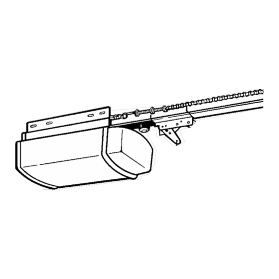
DRIVE CHAIN OPENER HEAD UNIT DOOR MOUNTING CONTROL WIRE BRACKET SPOOL RELEASE OPENER ROPE HARDWARE AND KNOB RUBBER BUMPER NOTE: The Tee 104363 Rail/Chain Assembly is packaged separately from the Power Unit. The Inner Trolley half, Front Idler Sprocket, Chain, and Limit Cams are assembled on the Tee Rail at the factory. -
Page 4: Identify Your Door Type
JAMB HARDWARE HIGH ARC OF DOOR TRAVEL TRACK DOOR JAMB HARD- PIVOT WARE THE MODEL MVP SERIES IN NOT DESIGNED TO OPERATE THESE TYPES OF DOORS DOWN LIMIT 104366 ONE PIECE DOOR NO TRACK PIVOT HARDWARE HIGH ARC OF DOOR TRAVEL... -
Page 5: Important Installation Instructions
IMPORTANT INSTALLATION INSTRUCTIONS WARNING! RISK OF SEVERE INJURY OR DEATH READ AND FOLLOW ALL INSTALLATION INSTRUCTIONS! AN UNBALANCED DOOR OR ONE THAT STICKS OR BINDS MAY PREVENT THE SENSING SYSTEM FROM WORKING PROPERLY, CAUSING INJURY OR DEATH. ENSURE DOOR IS PROPERLY BALANCED AND ELIMINATE ANY STICKING OR BINDING PRIOR TO INSTALLATION OF OPENER. -
Page 6: Installing The Opener
INSTALLING THE OPENER VERTICAL 104369 CENTERLINE HORIZONTAL LINE VERTICAL CENTERLINE 104371 LAG SCREWS 5/16” X 1-7/8” FRONT MOUNTING BRACKET MUST BE INSTALLED TO A STRUCTURAL SUPPORT (STUD) ON THE HEADER WALL. FAILURE TO DO SO COULD CAUSE SENSING SYSTEM TO MALFUNCTION, RESULTING IN ENTRAPMENT, INJURY OR DEATH. -
Page 7: Mounting The Power Head
Mounting Bracket. (See Step 2, previous). 111205 MVP-SQ NOTE: The Model MVP-SQ is provided with vibration isolator mounts. Position as shown above. STEP 6: Tie a double overhand knot in one end of the Manual Release Rope and slip the other end through the red Release Handle, the Release Instruction Card, and the hole at the end of the Release Lever on the Trolley. -
Page 8: Door Arm Installation
INSTALLING THE OPERATOR FIBERGLASS, ALUMINUM OR LIGHTWEIGHT STEEL GARAGE DOORS WILL REQUIRE REINFORCEMENT BEFORE INSTALLATION OF DOOR MOUNTING BRACKET. CONTACT CAUTION! YOUR DOOR MANUFACTURER FOR A REINFORCEMENT KIT DOOR ARM CONNECTION AND INSTALLATION NOTE: If the door is of light construction it is necessary to reinforce the center stile with steel angle or wood to prevent damage to the door if it encounters an obstruction on closing. -
Page 9: Power Requirements/Permanent Wiring
STEP 9 Consult the label on the rear panel of the Opener to determine its proper working voltage. Normally it will be marked for 115V, 60 cycle operation. (If it is an export model designed for 220V, 50 cycle operation, the label will clearly indicate this.) The Opener must be plugged into a properly grounded receptacle within 3 FT of the Power Unit. -
Page 10: Control And Auxiliary Equipment
CONTROL AND AUXILIARY EQUIPMENT INSTALLATION OF A STANDARD WALL PUSH BUTTON If desired, a standard wall push button may be installed and connected to your operator. A standard wall push button is not included in your hardware package, it can be purchased from your professional installing dealer or a door bell button [without light] can be substituted. -
Page 11: Remote Control Radio System
CONTROL AND AUXILIARY EQUIPMENT STEP 4: Run the wire from the Super Station to the opener, supporting it at 18” intervals with suitable staples. Leave a sufficient length to make the necessary connections to the opener terminal strip. WARNING: SOME LOCAL BUILDING CODES DO NOT ALLOW SURFACE WIRING. -
Page 12: Fcc And Ic Radio Operation Statement
Battery Replacement The MVP Quik-Code transmitter is provided with two factory installed 3-volt batteries which should be replaced after two years of normal use. The transmitter code is retained in permanent memory and will not be lost during battery replacement. -
Page 13: Installation Of Safe Finish Photosystem
LED on the rear panel of the power head unit will blink two times rapidly if it has accepted a valid transmitter signal. If the LED light does not blink reprogram the MVP power head unit to accept the transmitter signal by following the previous instructions “Programming the... -
Page 14: Installation Checklist
CONTROL AND AUXILIARY EQUIPMENT F. Using two (2) wire nuts (supplied), connect the wire ends at the SAFE FINISH™ Photosystem receiver to the pigtail wire ends coming out of the receiver unit. Although not required, it is recommended to connect the trace wire ends together and the unmarked wire ends together. -
Page 15: Operation And Adjustment Instructions
OPERATION AND ADJUSTMENT INSTRUCTIONS IMPORTANT SAFETY INSTRUCTIONS WARNING! RISK OF SEVERE INJURY OR DEATH READ AND FOLLOW ALL INSTRUCTIONS! • NEVER LET CHILDREN OPERATE OR PLAY WITH DOOR CONTROLS. KEEP THE REMOTE CONTROL AWAY FROM CHILDREN. • ALWAYS KEEP A MOVING DOOR IN SIGHT AND KEEP PEOPLE AND OBJECTS AWAY FROM THE DOOR AREA UNTIL THE DOOR IS COMPLETELY CLOSED. -
Page 16: Testing The Limit Settings
OPERATION AND ADJUSTMENT INSTRUCTIONS STEP 1: Testing the Limit Settings: To check the Limit Settings, start the Opener by pushing the standard wall Push Button or Super Station. Be prepared to activate the button again quickly - per the Operating Parameters outlined above - or if you see that the door is going to over travel. -
Page 17: Testing The Safe Finish Photosystem
OPERATION AND ADJUSTMENT INSTRUCTIONS Down force adjustments are correct, the door will reverse within two seconds of contacting the object and travel to the Full Open position. If this does not occur, recheck the Limit Adjustments (Step 1, previous) and Sensitivity 1 1/2”... -
Page 18: Wiring Diagram
OPERATION AND ADJUSTMENT INSTRUCTIONS 104394 OPEN Button CLOSE Enable Button Button Security Disable Security Switch Switch 2. Close Pushbutton — Green-backlighting, arrow pointing down. Used to start the door downward. This button has no effect on a door in motion. Will allow constant pressure close operation if the photocell is misaligned. -
Page 19: Auxiliary Equipment Wiring Diagram
108971 existing wiring can be used. See the figures above. Improved Sunlight Immunity. Under certain conditions, direct sunlight can overpower photobeam systems. We have provided an extra internal circuitry to reduce sunlight problems. When required, the position of the transmitter and receiver may be interchanged with out rewiring. TROUBLESHOOTING GUIDE USE EXTREME CAUTION AT ALL TIMES WHEN ATTEMPTING TO DIAGNOSE AND RECTIFY PROBLEMS WITH YOUR GARAGE DOOR OPENER. -
Page 20: Warranty Statement
Manufacturer’s Limited Warranty AllStar Pro, LLC warrants its MVP Series residential vehicular garage door operators as follows: The drive train to be free from defects in materials and workmanship for: Model MVP-SQ: The entire period of ownership by the original purchaser Models MVP: for 20 years from the date of purchase by the original purchaser.