Table of Contents
Advertisement
Available languages
Available languages
OPERATOR'S MANUAL
5 in. FLOORiNg SAw
MANUEL D'UTiLiSATiON
SCiE À PLANChER DE 127 mm (5 po)
MANUAL DEL OPERADOR
SiERRA PARA PiSOS DE 127 mm
(5 pulg.)
RLS1351
Your flooring saw has been engineered and manufactured to our high standard for dependability, ease of operation, and
operator safety. When properly cared for, it will give you years of rugged, trouble-free performance.
wARNiNg:
To reduce the risk of injury, the user must read and understand the operator's manual before using
this product.
Thank you for purchase.
SAVE ThiS MANUAL FOR FUTURE REFERENCE
Cette scie à plancher a été conçue et fabriquée conformément
à nos strictes normes de fiabilité, simplicité d'emploi et sécurité
d'utilisation. Correctement entretenue, elle vous donnera des
années de fonctionnement robuste et sans problème.
AVERTiSSEMENT :
blessures, l'utilisateur doit lire et veiller à bien comprendre le
manuel d'utilisation avant d'employer ce produit.
Merci de votre achat.
CONSERVER CE MANUEL POUR
FUTURE RÉFÉRENCE
Pour réduire les risques de
Su sierra para pisos ha sido diseñado y fabricado de conformidad
con nuestras estrictas normas para brindar fiabilidad, facilidad de
uso y seguridad para el operador. Con el debido cuidado, le brindará
muchos años de sólido y eficiente funcionamiento.
ADVERTENCiA:
el usuario debe leer y comprender el manual del operador antes
de usar este producto.
Le agradecemos su compra.
gUARDE ESTE MANUAL PARA
FUTURAS CONSULTAS
Para reducir el riesgo de lesiones,
Advertisement
Chapters
Table of Contents

Related Manuals for Ryobi RLS1351


Summary of Contents for Ryobi RLS1351
- Page 1 SiERRA PARA PiSOS DE 127 mm (5 pulg.) RLS1351 Your flooring saw has been engineered and manufactured to our high standard for dependability, ease of operation, and operator safety. When properly cared for, it will give you years of rugged, trouble-free performance.
-
Page 2: Table Of Contents
Center. You can obtain the location of the Service Center nearest you by contacting a service representative at One World Technologies, Inc., P.O. Box 1207, Anderson, SC 29622-1207, by calling 1-800-525-2579 or by logging on to www.ryobi- tools.com. When you request warranty service, you must also present proof of purchase documentation, which includes the date of purchase (for example, a bill of sale). -
Page 3: General Safety Rules
gENERAL SAFETy RULES SECURE wORK. Use clamps or a vise to hold work wARNiNg: when practical, it is safer than using your hand and frees both hands to operate the tool. Read and understand all instructions. Failure to follow ... - Page 4 gENERAL SAFETy RULES NEVER USE iN AN EXPLOSiVE ATMOSPhERE. USE ONLy CORRECT BLADES. Do not use blades with Normal sparking of the motor could ignite fumes. incorrect size holes. Never use blade washers or blade bolts that are defective or incorrect. The maximum blade ...
-
Page 5: Specific Safety Rules
SPECiFiC SAFETy RULES iF ANy PART OF ThiS SAw iS MiSSiNg or should KEEP hANDS AwAy FROM CUTTiNg AREA. Do not break, bend, or fail in any way, or should any electrical reach underneath work or in blade cutting path with hands component fail to perform properly, shut off the power and fingers for any reason. -
Page 6: Symbols
SyMBOLS The following signal words and meanings are intended to explain the levels of risk associated with this product. SyMBOL SigNAL MEANiNg Indicates an imminently hazardous situation, which, if not avoided, will result DANgER: in death or serious injury. Indicates a potentially hazardous situation, which, if not avoided, could result wARNiNg: in death or serious injury. -
Page 7: Electrical
ELECTRiCAL DOUBLE iNSULATiON EXTENSiON CORDS Double insulation is a concept in safety in electric power When using a power tool at a considerable distance from tools, which eliminates the need for the usual three- a power source, be sure to use an extension cord that has wire grounded power cord. -
Page 8: Glossary Of Terms
gLOSSARy OF TERMS Anti-Kickback Pawls (flooring, radial arm, and table Push Blocks (jointer planers) saws) Device used to feed the workpiece over the jointer planer A device which, when properly installed and maintained, cutterhead during any operation. This aid helps keep the is designed to stop the workpiece from being kicked back operator’s hands well away from the cutterhead. -
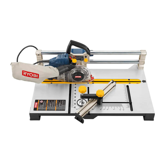
Page 9: Features
FEATURES PRODUCT SPECiFiCATiONS Blade Diameter .............5 in. Miter Capacity ............11 in. Blade Arbor .............. 5/8 in. Input ..........120 V~, 60 Hz, 7 Amps Rip Capacity ..............8 in. No Load Speed ........11,000 r/min. (RPM) KNOw yOUR FLOORiNg SAw BLADE wRENCh STORAgE - A blade wrench is packed with the saw. -
Page 10: Assembly
ASSEMBLy LOOSE PARTS LiST wARNiNg: See Figure 2, page 17. Do not attempt to modify this product or create acces- The following items are included with the saw: sories not recommended for use with this tool. Any such alteration or modification is misuse and could result in a Description Qty. - Page 11 ASSEMBLy TO iNSTALL ThE FEET TO ThE SAw BASE TO iNSTALL FENCE FOR MAKiNg RiP CUTS See Figure 9, page 19. See Figure 6, page 18. Align hole in foot with hole in saw base. Remove the work clamp from the fence. Do not tighten attachment bolt.
-
Page 12: Assembly
ASSEMBLy TO iNSTALL / REPLACE ThE BLADE Replace the outer blade washer. Double “D” flats on blade washers align with flats on spindle. See Figures 11 - 12, pages 19 - 20. Depress spindle lock button and replace blade bolt. wARNiNg: CAUTiON: A 5 in. -
Page 13: Operation
OPERATiON balanced position to be ready to resist kickback should wARNiNg: it occur. Never stand directly in line with the blade. Clean the saw, blade guard, under the throat plate, and Do not allow familiarity with tools to make you care- any areas where saw dust or scrap workpieces may less. - Page 14 OPERATiON TO RAiSE AND LOwER ANTi-KiCKBACK wARNiNg: PAwLS See Figure 18, page 21. ALWAYS make sure your workpiece is not in contact with the blade before operating the switch to start the tool. The anti-kickback pawls are only used for making rip cuts. Failure to heed this warning may cause the workpiece to These pawls are spring-loaded and very sharp.
- Page 15 OPERATiON Align cutting line on the workpiece with the edge of saw blade. Use the work clamp to secure the workpiece. Do wARNiNg: not overtighten. Always keep hands and body out of the path of the saw Make sure the wood is clear of the blade before turning blade.
-
Page 16: Maintenance
MAiNTENANCE Clean the fence and rails with a gum and pitch remover. wARNiNg: Clean plastic parts only with a soft damp cloth. DO NOT use any aerosol or petroleum solvents. When servicing, use only identical replacement parts. Use of any other parts may create a hazard or cause LUBRiCATiON product damage. - Page 17 POLITIQUE D’ÉCHANGE DE 30 JOURS : En cas de défaillance due à des vices de matériaux ou de fabrication au cours des 30 jours suivant la date d’achat, l’acheteur pourra faire réparer tout outil électrique RyObI au titre de cette garantie ®...
-
Page 18: Règles De Sécurité Générales
RÈGLES DE SÉCURITÉ GÉNÉRALES PORTER UNE TENUE APPROPRIÉE. Ne pas porter de AVERTISSEMENT : vêtements amples, cravates, ou bijoux susceptibles de se prendre et vous entraîner dans les pièces mobiles. Des Lire et veiller à bien comprendre toutes les gants en caoutchouc et des chaussures antidérapantes instructions. - Page 19 RÈGLES DE SÉCURITÉ GÉNÉRALES PORTER UNE PROTECTION AUDITIVE. Porter une RESTER VIGILANT ET GARDER LE CONTRÔLE. Se montrer attentif et faire preuve de bon sens. Ne pas utiliser protection auditive durant les périodes d’utilisation prolongée. l’outil en état de fatigue. Ne pas se presser. ...
-
Page 20: Règles De Sécurité Particulières
RÈGLES DE SÉCURITÉ PARTICULIÈRES GARDER LES MAINS À L’ÉCART DE LA ZONE DE ce soit, ou si un composant électrique quel qu’il soit COUPE. Ne placer en aucun cas la main ou les doigts ne fonctionne pas correctement, éteindre la scie, la au-dessous de la pièce à... -
Page 21: Symboles
SYMBOLES Les termes de mise en garde suivants et leur signification ont pour but d’expliquer le degré de risques associé à l’utilisation de ce produit. SYMBOLE SIGNAL SIGNIfICATION Indique une situation extrêmement dangereuse qui, si elle n’est pas évitée, DANGER : aura pour conséquences des blessures graves ou mortelles. -
Page 22: Caractéristiques Électriques
CARACTÉRISTIQUES ÉLECTRIQUES DOUBLE ISOLATION CORDONS PROLONGATEURS La double isolation est un dispositif de sécurité utilisé sur les Lors de l’utilisation d’un outil électrique à grande distance outils à moteur électriques, éliminant le besoin de cordon d’une prise secteur, veiller à utiliser un cordon prolongateur d’alimentation habituel à... -
Page 23: Glossaire
GLOSSAIRE Trou pilote (perceuses à colonne) Griffes antirebond (scies à plancher, radiales et table) Petit trou pratiqué dans une pièce servant de guide pour Dispositifs qui, s’ils sont correctement installés et entrete- assurer la précision d’un trou de plus grand diamètre. nus, sont conçus pour empêcher que la pièce coupée soit propulsée en direction de l’opérateur durant la refente. -
Page 24: Caractéristiques
CARACTÉRISTIQUES PRODUCT SPECIfICATIONS Diamètre de la lame ........127 mm (5 po) Capacité de d’onglet ......... 279 mm (11 po) Axe de lame ..........16 mm (5/8 po) Alimentation ........120 V~, 60 Hz, 7 Amps Capacité de refente ........203 mm (8 po) Vitesse à... -
Page 25: Assemblage
ASSEMBLAGE LISTE DES PIÈCES DÉTACHÉE Voir la figure 2, page 17. AVERTISSEMENT : Les articles suivants sont inclus avec le scie : Ne pas essayer de modifier cet outil ou de créer des No. de accessoires non recommandés pour ce produit. De Pièce Description Qté. - Page 26 ASSEMBLAGE POUR INSTALLER LE PIEDS À LA BASE DE POUR INSTALLER DU GUIDE POUR fAIRE LA SCIE COUPES LONGITUDINAL Voir la figure 6, page 18. Voir la figure 9, page 19. Aligner le trou dans le pied avec le trou dans la base de ...
- Page 27 ASSEMBLAGE INSTALLATION / REMPLACEMENT DE LA LAME ATTENTION : Voir les figures 11 - 12, pages 19 - 20. Toujours installer la lame avec les dents et la flèche AVERTISSEMENT : imprimée sur son côté, orientées vers le haut à l’avant de la scie.
-
Page 28: Utilisation
UTILISATION campé afin de pouvoir la maîtriser en cas de rebond. Ne jamais se tenir en ligne avec la lame. AVERTISSEMENT : Nettoyer la scie, le protège-lame, sous la plaque à gorge, Ne pas laisser la familiarité avec l’outil faire oublier la et n’importe quels sciure où... - Page 29 UTILISATION POUR RELEVER ET ABAISSER GRIffES ANTI- AVERTISSEMENT : REBOND Voir la figure 18, page 21. TOUJOURS s’assurer que la pièce n’est pas en contact avec la lame avant de mettre le commutateur de l’outil en Les griffes antirebond ne sont utilisés que pour faire des position de marche.
- Page 30 UTILISATION Aligner la ligne de coupe de la pièce sur le bord de la AVERTISSEMENT : lame. Utiliser un bride de serrage pour maintenir la pièce. No serrez pas trop. Toujours garder les mains et le corps hors du passage ...
-
Page 31: Entretien
ENTRETIEN Vérifier la garde de lame. AVERTISSEMENT : Nettoyer les le guide et les rails avec un produit pour résine et gommes. Utiliser exclusivement des pièces d’origine pour les Nettoyer les pièces en plastique uniquement avec un réparations. - Page 32 One World Technologies, Inc., garantiza sus herramientas eléctricas con las siguientes condiciones: POLÍTICA DE INTERCAMBIO A LOS 30 DÍAS: Durante los primeros 30 días a partir de la fecha de compra, usted puede solicitar servicio al amparo de esta garantía o puede intercambiar cualquier herramienta eléctrica RYOBI que no funcione ®...
-
Page 33: Reglas De Seguridad Generales
REGLAS DE SEGURIDAD GENERALES (A.W.G.) por lo menos, para un cordón de extensión de ADVERTENCIA: 7,6 metros (25 pies) de largo o menos. Si tiene dudas, utilice un cordón del calibre más grueso siguiente. Cuanto Lea y comprenda todas las instrucciones. El menor es el número de calibre, mayor es el grueso del incumplimiento de las instrucciones señaladas abajo puede causar descargas eléctricas, incendios y lesiones... - Page 34 REGLAS DE SEGURIDAD GENERALES AVANCE LA PIEZA DE TRABAJO EN LA DIRECCIÓN MANTENGA LA HERRAMIENTA SECA, LIMPIA Y CORRECTA. Solamente empuje la pieza de trabajo hacia LIBRE DE ACEITE Y GRASA. Siempre utilice un paño la hoja o fresa contra el sentido de rotación de éstos. limpio para la limpieza de la unidad.
-
Page 35: Reglas De Seguridad Específicas
REGLAS DE SEGURIDAD ESPECÍFICAS MANTENGA LAS MANOS ALEJADAS DEL ÁREA DE retire la clavija del suministro de corriente y llame a un técnico para que reemplace toda pieza dañada, faltante CORTE. No trate de alcanzar bajo la pieza de trabajo o en o defectuosa antes de reanudar el trabajo. -
Page 36: Símbolos
SÍMBOLOS Las siguientes palabras de señalización y sus significados tienen el objeto de explicar los niveles de riesgo rela- cionados con este producto. SÍMBOLO SEÑAL SIGNIFICADO Indica una situación peligrosa inminente, la cual, si no se evita, causará la muerte o lesiones serias. PELIGRO: Indica una situación peligrosa posible, la cual, si no se evita, podría causar ADVERTENCIA:... -
Page 37: Aspectos Eléctricos
ASPECTOS ELÉCTRICOS DOBLE AISLAMIENTO CORDONES DE EXTENSIÓN El doble aislamiento es una característica de seguridad de las Al utilizar una herramienta eléctrica a una distancia herramientas eléctricas, la cual elimina la necesidad de usar considerable de la fuente de voltaje, asegúrese de utilizar el típico cordón eléctrico de tres conductores con conexión un cordón de extensión con la suficiente capacidad para a tierra. -
Page 38: Glosario De Términos
GLOSARIO DE TÉRMINOS Trinquetes anticontragolpe (sierras cortar pisos, radiales Bloques empujadores (para cepillos de juntas) y de mesa) Son dispositivos empleados para avanzar la pieza de trabajo por Es un dispositivo, el cual, cuando se instala y da mantenimiento el cepillo de juntas durante cualquier operación. Este medio ayuda correctamente, sirve para detener la pieza de trabajo para no al operador a mantener las manos alejadas de la cabeza de corte. -
Page 39: Características
CARACTERÍSTICAS ESPECIFICACIONES DEL PRODUCTO Diámetro de la hoja ......... 127 mm (5 pulg.) Capacidad de inglete ......279 mm (11 pulg.) Árbol de la hoja de corte ......16 mm (5/8 pulg.) Corriente de entrada ..... 120 V~, 60 Hz, 7 Amps Capacidad de corte al hilo ...... -
Page 40: Armado
ARMADO LISTA DE PIEZAS SUELTAS ADVERTENCIA: Vea la figura 2, página 17. Los siguientes accesorios vienen incluidos con sierra: No intente modificar esta producto ni hacer accesorios no recomendados para la misma. Cualquier alteración o Núm. modificación constituye maltrato el cual puede causar ref. - Page 41 ARMADO PARA INSTALAR LOS PIES A LA BASE DE LA PARA INSTALAR LA GUÍA PARA CORTES AL SIERRA HILO Vea la figura 6, página 18. Vea la figura 9, página 19. Alinee el agujero en el pata con el agujero en la base de ...
- Page 42 ARMADO PARA INSTALAR O REEMPLAZAR LA HOJA PRECAUCIÓN: Vea las figuras 11 - 12, páginas 19 - 20. Siempre instale la hoja con los dientes de la misma y la flecha impresa en el costado de la hoja apuntando hacia ADVERTENCIA: arriba en la parte frontal de la sierra.
-
Page 43: Funcionamiento
FUNCIONAMIENTO estar preparado para resistir un contragolpe si llega a ADVERTENCIA: ocurrir. Nunca se pare en línea frente a la hoja. Limpie el sierra, protección de la hoja, bajo el placa de No permita que su familarización con las herramientas lo la garanta, y bajo cualquier área donde sierra o pieza de vuelva descuidado. - Page 44 FUNCIONAMIENTO PARA LEVANTE Y BAJE TRINQUETES ANTI- ADVERTENCIA: CONTRAGOLPE Vea la figura 18, página 21. Cuando no esté en uso la herramienta, SIEMPRE retire Los trinquetes anticontragolpe sólo se utilizan para hacer la llave del interruptor y guárdela en un lugar seguro. En cortes al hilo.
- Page 45 FUNCIONAMIENTO asegurar la pieza de trabajo. No apriete demasiado. ADVERTENCIA: Asegúrese de que la madera está lejos de la hoja antes de encender la sierra. Siempre mantenga las manos y el cuerpo fuera de la Coloque el interruptor de corriente en la posición de trayectoria de la hoja.
-
Page 46: Mantenimiento
MANTENIMIENTO Revise el sistema protector de la hoja. ADVERTENCIA: Limpie las guía y rieles con un limpiador de goma y resina. Al dar servicio a la unidad, sólo utilice piezas de repuesto Limpie las piezas de plástico solamente con un paño idénticas. -
Page 47: Loose Parts
Fig. 1 J - Saw handle (poignée de la scie, mango de la sierra) A - Work clamp (bride de serrage de pièce, prensa de trabajo) B - Dust bag (sac à sciure, saco captapolvo) K - Push stick storage (rangement bâton poussoir,... - Page 48 Fig. 3 Fig. 5 A - Saw Handle (poignée de la scie, mango de la sierra) A - Foot (pied, pies) B - Phillips screw (vis phillips, tornillo phillips) B - Mounting board (planche de montage, tabla de montaje) C - Washer (rondelle, arandela) Fig.
- Page 49 Fig. 7 Fig. 9 A - Fence (guide, guía) B - Attachment bolt (boulon de fixation, perno de fijacion) C - Adjusting clamp (serre-guide, grampa de ajuste) A - Fence (guide, guía) D - Clamp knob (bouton de serrage, perilla de sujeción) B - Rip groove (rainure longitudinal, rainure longitudinal) E - Work clamp (bride de serrage de pièce, prensa de trabajo) C - Left groove (rainure gauche, ranura izquierdo)
- Page 50 Fig. 12 Fig. 14 A - Blade bolt (boulon de la lame, perno de la hoja) B - Blade bolt cover (couvercle de protège-lame, cubierta del perno de la hoja) C - Outer blade washer (rondelle de lame extérieure, arandela exterior de la hoja) D - Screw (vis, tornillo) E - Blade (lame, hoja)
- Page 51 Fig. 15 Fig. 17 A - Push sticks (bâtons poussoirs, palos empujadoras) B - Push blocks (blocs-poussoirs, bloques empujadores) Fig. 16 A - Indicator (indicateur, indicador) B - Blade guard adjustment knob (bouton de réglage de protège- lame, perilla de ajuste de la protección de la hoja) C - Indicator screw (vis de indicateur, tornillo de indicador) Fig.
- Page 52 Fig. 19 Fig. 21 rip cut cross cut (coupe loNGitudiNal, (coupe traNsversale, corte al hilo) cortes traNsversales) Fig. 22 Narrow rip cut (coupe loNGitudiNal étroit, corte al hilo estrecho) Fig. 20 Miter cut (coupe d’oNGlet, corte a iNGlete) Fig. 23 A - Throat plate (plaque à...
- Page 53 NOTES/NOTAS...
- Page 54 NOTES/NOTAS...
- Page 55 NOTES/NOTAS...
- Page 56 OBtENER SERvIcIO O ASIStENcIA tÉcNIcA AL cONSUMIDOR: para obtener Servicio o Asistencia técnica al consumidor, sírvase comunicarse con nosotros llamando al 1-800-525-2579. RYOBI es una marca comercial registrada de Ryobi Limited y es empleada mediante autorización. ® ONE wORLD TEChNOLOgIES, INC.