ADEMCO 6128 Installation Instructions And Operating Manual
Wireless bi-directional keypads used with 5800tm transmitter module
Hide thumbs
Also See for 6128:
- User instructions (12 pages) ,
- Installation manual (2 pages) ,
- User manual (9 pages)
Advertisement
Quick Links
For use with Q.E.D. control panels only.
INSTALLATION INSTRUCTIONS and OPERATING GUIDE
Unless otherwise indicated, all information in this manual is applicable to both the 5827BD and 5827BDE
GENERAL INFORMATION
T
he 5827BD and 5827BDE Wireless Bi-directional Keypads are
designed to be used in conjunction with a 5800TM Transmitter
Module. Additional 5827BDs (any quantity) may be used in
conjunction with the same 5800TM; however, no more than eight
5827BDEs may be used. The 5800TM is compatible with any
control panel that is also equipped with a 4281 type (5700 System)
or 5881 type (5800 System) RF receiver.
Note: The 5827BDE is an enhanced version of the 5827BD and
employs AdemcoÕs new SignalSentryª technology, which
can provide high security wireless transmissions when used
in conjunction with the 5881EH RF receiver.
The 5827BD and 5827BDE can operate the protection system
similarly to other wireless keypads, via keypad buttons. In addition,
three LEDs (Red, Green, and Yellow) and a piezoelectric sounder
can indicate status information relative to:
System arming/trouble/emergency, RF transmission/confirmation,
and 5827BD/5827BDE programming and power.
The keypad configuration is similar to that of standard keypads. The
[ ] key, however, is also the [ON/STAT] (power-up and system
status inquiry) key instead of a "READY" key, as it is on other
keypads (see OPERATION ). There are three panic keys: A, B, and
C, comparable to the individual keys (or panic key pairs of [1] & [
[
& [#], and [3] & [#] respectively) on other keypads.
]
The 5827BD and 5827BDE keypads, if so-programmed, also
feature "Quick Key" operation, which allows use of the [#] key
instead of entry of the security code when performing functions.
5800TM Transmitter Module
For every installation of one or more 5827BD or 5827BDE Wireless
Keypads, one 5800TM is required. The 5800TM complements the
RF receiver in that it transmits the information to be displayed on, or
sounded by, the 5827BD or 5827BDE. No modification to the
control is necessary. The 5800TM connects directly to the control's
wired keypad connection points, as described later.
5827BD & 5827BDE INSTALLATION
The 5827BD and 5827BDE are designed to be portable, for use
throughout the protected premises. If desired, a wireless keypad
may be stored on its accompanying mounting bracket (easily
installable via two countersunk mounting holes). Keyhole slots on
the rear of the keypad slip onto two hooks on the mounting bracket,
allowing the keypad to be easily removed when desired .
When operating, or selecting a location for storing the wireless
keypad, observe the same precautions as used for locating the
wireless system's other transmitters (see the control panel's
instruction manual). For example, operating the keypad on or near
large metal objects may decrease range and/or block
transmissions.
1. Install the keypad's 9-volt Alkaline battery. S lide off the
battery compartment cover at the rear of the keypad and insert
the battery. Observe polarity! Then replace the cover.
2. Program the keypad's memory as indicated next.
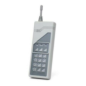
5827BD and 5827BDE
WIRELESS BI-DIRECTIONAL KEYPADS
Used with 5800TM Transmitter Module
ANTENNA
(OPTIONAL)
SOUNDER
LEDS
GREEN
YELLOW
RED
C (3/#)
B ( /#)
,
]
A (1/ )
PANIC KEYS
AFFIX
PANIC KEY
LABELS HERE
POWER-UP KEY
Programming the Wireless Keypad
a. Power up the keypad by depressing the [ ] key. The
yellow LED will blink.
If the keypad was previously programmed, the system
status may also be annunciated (see Power-up and
System Status Inquiry on the next page).
b. Enter the keypad programming mode by
depressing both the [1] and [3] keys at the same time
for 3 seconds.
Alternate blinking of the red and green LEDs confirms
that the unit is in the keypad programming mode.
c. Program the desired functions, in the order given
in the Programming table that follows. Note that
every sequence starts with a [ ] and ends with a [#].
Previous Menu
N6484V3 3/96
ARM
SEND/RCV
READY
1
2
3
4
5
6
7
8
9
*
0
#
5827BD
Advertisement

Related Manuals for ADEMCO 6128


Summary of Contents for ADEMCO 6128
- Page 1 For use with Q.E.D. control panels only. Previous Menu N6484V3 3/96 5827BD and 5827BDE WIRELESS BI-DIRECTIONAL KEYPADS Used with 5800TM Transmitter Module INSTALLATION INSTRUCTIONS and OPERATING GUIDE Unless otherwise indicated, all information in this manual is applicable to both the 5827BD and 5827BDE GENERAL INFORMATION he 5827BD and 5827BDE Wireless Bi-directional Keypads are designed to be used in conjunction with a 5800TM Transmitter...
-
Page 2: Operation
PROGRAMMING TABLE FOR 5827BD AND 5827BDE* Note: A section later in this manual provides the necessary information for enrolling the 5827BDE as a SignalSentry (high security) device. See Enrolling the 5827BDE as a SignalSentry Device. However, the 5827BDE must first be set up and tested in its normal operating mode, as indicated in the following sections FUNCTION ENTER... - Page 3 Approximately 10 seconds after the last key depression, the The following table shows the various status indications that can wireless keypad will automatically power down. occur during the time that the unit is powered up. No subsequent LED or sound indications will occur until the unit is again powered up (thus, in chime mode, the chime is not annunciated by the wireless keypad).
- Page 4 Alarm Memory successfully enrolled, the system status will be displayed by one of the LEDs on the 5827BDE after a few seconds If the [ON/STAT] key is pressed during or following a fire or (armed or ready,). At this time, some systems will emit 3 burglary alarm sounding period, the wireless keypad will beeps from the wired keypad(s).
- Page 5 1. Place the control panel in the Go/No Go TEST mode (this will times before exiting the keypad programming mode. If reduce the receiver sensitivity). asingle long beep is heard, the 5827BDE was either not in theSignalSentry mode, is not a 5827BDE, or the key 2.
-
Page 6: Ademco Limited Warranty
5827BD/5827BDE SPECIFICATIONS Physical: 2-3/8" W x 6-1/4" H x 1-1/4" D (61mm x 159mm x 32mm) Battery: 9-volt Alkaline. Ademco 464, Duracell MN1604, or Eveready 522 (If a low battery condition exists, it will be displayed on wired keypads as zone 00.) LEDs: Red, Green, and Yellow, for system status indications.