Table of Contents
Advertisement
Advertisement
Table of Contents

Related Manuals for Asus P4P800-E DELUXE


Summary of Contents for Asus P4P800-E DELUXE
- Page 1 P4P800-E Deluxe User Guide...
- Page 2 Product warranty or service will not be extended if: (1) the product is repaired, modified or altered, unless such repair, modification of alteration is authorized in writing by ASUS; or (2) the serial number of the product is defaced or missing.
-
Page 3: Table Of Contents
How this guide is organized ..........ix Where to find more information ..........ix Conventions used in this guide ..........x Typography ................x P4P800-E Deluxe specifications summary ........xi Chapter 1: Product introduction 1.1 Welcome! ................1-1 1.2 Package contents ............... 1-1 1.3 Special features .............. - Page 4 Using AFUDOS to update the BIOS ...... 4-2 4.1.3 Using AFUDOS to copy BIOS from PC ....4-3 4.1.4 Using ASUS EZ Flash to update the BIOS .... 4-4 4.1.5 Recovering the BIOS with CrashFree BIOS 2 ..4-5 4.1.6 ASUS Update ............
- Page 5 5.1 Install an operating system ..........5-1 5.2 Support CD information ............5-1 5.2.1 Running the support CD ........5-1 5.2.2 Drivers menu ............5-2 5.2.3 Utilities menu ............5-3 5.2.4 ASUS Contact Information ........5-4 5.2.5 Other information ........... 5-5...
- Page 6 Contents 5.3 Software Information ............5-7 5.3.1 ASUS MyLogo2™ ..........5-7 5.3.2 ASUS Instant Music ..........5-9 5.4 AI Net feature ..............5-12 5.5 Audio configurations ............5-13 5.5.1 Sound Effect options ..........5-13 5.5.2 S/PDIF options ............. 5-14 5.5.3 Speaker Configuration .........
-
Page 7: Notices
Notices Federal Communications Commission Statement This device complies with Part 15 of the FCC Rules. Operation is subject to the following two conditions: • This device may not cause harmful interference, and • This device must accept any interference received including interference that may cause undesired operation. -
Page 8: Safety Information
Safety information Electrical safety • To prevent electrical shock hazard, disconnect the power cable from the electrical outlet before relocating the system. • When adding or removing devices to or from the system, ensure that the power cables for the devices are unplugged before the signal cables are connected. -
Page 9: About This Guide
Refer to the following sources for additional information and for product and software updates. 1. ASUS websites The ASUS website provides updated information on ASUS hardware and software products. Refer to the ASUS contact information. 2. Optional documentation Your product package may include optional documentation, such as warranty flyers, that may have been added by your dealer. -
Page 10: Conventions Used In This Guide
Conventions used in this guide To make sure that you perform certain tasks properly, take note of the following symbols used throughout this manual. DANGER/WARNING: Information to prevent injury to yourself when trying to complete a task. CAUTION: Information to prevent damage to the components when trying to complete a task. -
Page 11: P4P800-E Deluxe Specifications Summary
ASUS Hyper-Path Technology Expansion slots 1 x AGP 8X (0.8V, 1.5V only) 5 x PCI 1 x ASUS WiFi slot for optional wireless LAN upgrade ICH5R SouthBridge supports Storage - 2 x UltraDMA 100/66/33 - 2 x Serial ATA with RAID 0, RAID 1 function ®... - Page 12 Front panel audio connector Serial port 2 connector BIOS features 4Mb Flash ROM, AMI BIOS, PnP, DMI2.0, WfM2.0, SM BIOS 2.3, ASUS EZ Flash, ASUS Instant Music, ASUS MyLogo2, ASUS C.P.R., ASUS Multi-Language BIOS Industry standard PCI 2.2, PCI 2.3, USB 2.0 Manageability WfM2.0, DMI 2.0, WOL, WOR, chassis intrusion...
-
Page 13: Chapter 1: Product Introduction
Chapter 1 This chapter describes the motherboard features and the new technologies it supports. Product introduction... - Page 14 Chapter summary Welcome! ............1-1 Package contents .......... 1-1 Special features ..........1-2 ASUS P4P800-E Deluxe motherboard...
-
Page 15: Welcome
Thank you for buying the ASUS P4P800-E Deluxe motherboard! ® The motherboard delivers a host of new features and latest technologies making it another standout in the long line of ASUS quality motherboards! ® ® The motherboard incorporates the Intel... -
Page 16: Special Features
266 DIMMs. The ultra-fast 400MHz memory bus delivers the required bandwidth for the latest 3D graphics, multimedia, and Internet applications. ASUS Hyper-Path Technology This unique technology from ASUS optimizes the true potential of the ® Intel 865PE chipset to deliver the highest performance among competing 865PE-based solutions. - Page 17 480 Mbps on USB 2.0 - supporting up to 8 USB 2.0 ports. The higher bandwidth of USB 2.0 allows connection of devices such as high resolution video conferencing cameras, next generation scanners and printers, and fast storage units. USB 2.0 is backward compatible with USB 1.1. ASUS P4P800-E Deluxe motherboard...
-
Page 18: Unique Asus Features
1.3.2 Unique ASUS features ASUS Wi-Fi slot The ASUS Wi-Fi slot is designed for the ASUS WiFi-b™ add-on card to set up an environment for wireless LAN. The ASUS WiFi-b™ add-on card bundles the exclusive software Access Point (AP) to save the extra cost of a stand-alone AP. -
Page 19: Asus Mylogo2
4-31. CrashFree BIOS 2 This feature allows you to restore the original BIOS data from the ASUS support CD in case when the BIOS codes and data are corrupted. This protection eliminates the need to buy a replacement ROM chip. See page 4-5. - Page 20 See page 4-12. ASUS Instant Music This unique feature allows you to playback audio files even without booting the system to Windows™. Just press the ASUS Instant Music special function keys and enjoy the music! See pages 4-27, 5-9. ASUS BurnProof The motherboard offers a new design to prevent CPU, AGP, or memory slot burn caused by improper installation or insertion.
-
Page 21: Chapter 2: Hardware Information
Chapter 2 This chapter lists the hardware setup procedures that you have to perform when installing system components. It includes description of the jumpers and connectors on the motherboard. Hardware information... - Page 22 Chapter summary Before you proceed ........2-1 Motherboard overview ........2-2 Central Processing Unit (CPU) ..... 2-6 System memory ........... 2-12 Expansion slots ........... 2-15 Jumpers ............2-20 Connectors ........... 2-23 ASUS P4P800-E Deluxe motherboard...
-
Page 23: Before You Proceed
The illustration below shows the location of the onboard LED. SB_PWR ® P4P800-E Standby Powered Power P4P800-E Onboard LED ASUS P4P800-E Deluxe motherboard... -
Page 24: Motherboard Overview
Motherboard overview Before you install the motherboard, study the configuration of your chassis to ensure that the motherboard fits into it. Make sure to unplug the power cord before installing or removing the motherboard. Failure to do so may cause you physical injury and damage motherboard components. -
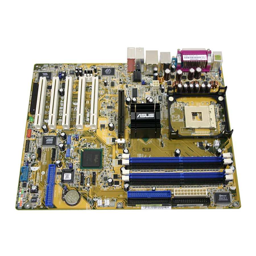
Page 25: Motherboard Layout
SATA1 PCI2 CR2032 3V MODEM Lithium Cell USBPW56 SMB20 CMOS Power USBPW78 4Mbit Firmware Audio CLRTC PCI3 Codec USB_56 USB_78 PRI_RAID P4P800-E FP_AUDIO SATA_RAID2 PCI4 SATA_RAID1 Speech Controller PCI5 CHASSIS COM2 IE1394_2 GAME PANEL WIFI SB_PWR ASUS P4P800-E Deluxe motherboard... -
Page 26: Layout Contents
2.2.4 Layout Contents Slots Page 1. PCI slots 2-18 2. AGP slot 2-18 3. Wi-Fi slot 2-19 4. DDR DIMM slots 2-12 Jumpers Page 1. Clear RTC RAM (3-pin CLRTC) 2-20 2. USB device wake-up (3-pin USBPW12, USBPW34, USBPW56, USBPW78) 2-21 3. -
Page 27: Internal Connectors
- System Warning Speaker Lead (Orange 4-pin SPKR) - Reset Switch (Blue 2-pin RESET) - ATX Power Switch (Yellow 2-pin PWRBTN) - System Management Interrupt Lead (Light Blue 2-pin SMI) - Hard Disk Activity LED (Red 2-pin IDE_LED) ASUS P4P800-E Deluxe motherboard... -
Page 28: Central Processing Unit (Cpu)
Central Processing Unit (CPU) 2.3.1 Overview The motherboard comes with a surface mount 478-pin Zero Insertion Force (ZIF) socket designed for the Intel ® Pentium ® 4 processor. Take note of the marked corner (with Gold Mark gold triangle) on the CPU. This mark should match a specific corner on the socket to ensure correct installation. -
Page 29: Installing The Cpu
90º~100º angle lever sideways, then lift it up to a 90 -100 angle. Socket Lever Make sure that the socket lever is lifted up to 90 -100 angle; otherwise, the CPU does not fit in completely. ASUS P4P800-E Deluxe motherboard... - Page 30 3. Position the CPU above the socket such that its marked Gold Mark corner matches the base of the socket lever. 4. Carefully insert the CPU into the socket until it fits in place. The CPU fits only in one correct orientation. DO NOT force the CPU into the socket to prevent bending the pins and damaging the CPU! 5.
-
Page 31: Installing The Heatsink And Fan
Your boxed Intel ® Pentium ® 4 processor package should come with installation instructions for the CPU, heatsink, and the retention mechanism. If the instructions in this section do not match the CPU documentation, follow the latter. ASUS P4P800-E Deluxe motherboard... - Page 32 2. Position the fan with the retention mechanism on top of the heatsink. Align and snap the four hooks of the retention mechanism to the holes on each corner of the module base. Make sure that the fan and retention mechanism assembly perfectly fits the heatsink and module base, otherwise you cannot snap the hooks into the holes.
-
Page 33: Connecting The Cpu Fan Cable
CPU fan cable to the connector on the motherboard labeled CPU_FAN. CPU Fan Connector (CPU_FAN) Do not forget to connect the CPU fan connector! Hardware monitoring errors may occur if you fail to plug this connector. ASUS P4P800-E Deluxe motherboard 2-11... -
Page 34: System Memory
System memory 2.4.1 Overview The motherboard comes with four Double Data Rate (DDR) Dual Inline Memory Module (DIMM) sockets. The following figure illustrates the location of the sockets. ® P4P800-E P4P800-E 184-Pin DDR DIMM Sockets 2.4.2 Memory configurations You may install 64 MB, 128 MB, 256 MB, 512 MB, and 1GB DDR DIMMs into the DIMM sockets using the memory configurations in this section. - Page 35 Memory Frequency 800 MHz PC3200/PC2700*/PC2100 400/333*/266 MHz 533 MHz PC2700/PC2100 333/266 MHz 400 MHz PC2100 266 MHz *When using 800MHz CPU FSB, PC2700 DDR DIMMs may run only at 320MHz (not 333MHz) due to chipset limitation. ASUS P4P800-E Deluxe motherboard 2-13...
-
Page 36: Qualified Vendor List
C* - support for 4 modules inserted into the blue & blackslots as two pairs of Dual-channel memory configuration. Obtain DDR DIMMs only from ASUS qualified vendors. Visit the ASUS website (www.asus.com) for the latest QVL. 2-14 Chapter 2: Hardware information... -
Page 37: Installing A Dimm
DIMM. Support the DIMM lightly with your fingers when pressing the retaining clips. The DIMM might get damaged when it flips out with extra force. 2. Remove the DIMM from the socket. ASUS P4P800-E Deluxe motherboard 2-15... -
Page 38: Expansion Slots
Expansion slots In the future, you may need to install expansion cards. The motherboard has available PCI slots and an Accelerated Graphics Port (AGP) slot. The following sub-sections describe the slots and the expansion cards that they support. Make sure to unplug the power cord before adding or removing expansion cards. -
Page 39: Interrupt Assignments
When using PCI cards on shared slots, ensure that the drivers support “Share IRQ” or that the cards do not need IRQ assignments. Otherwise, conflicts will arise between the two PCI groups, making the system unstable and the card inoperable. ASUS P4P800-E Deluxe motherboard 2-17... -
Page 40: Pci Slots
2.5.4 PCI slots The PCI slots support PCI cards such as a LAN card, SCSI card, USB card, and other cards that comply with PCI specifications. The following figure shows a LAN card installed on a PCI slot. • When installing long PCI cards, it is recommended that you install it in PCI slots 3, 4, or 5. -
Page 41: Wi-Fi Slot
2.5.6 Wi-Fi slot The Wi-Fi (Wireless Fidelity) slot supports the ASUS WiFi-b™ module. Visit the ASUS website (www.asus.com) for product updates. The Wi-Fi slot conforms to the Institute of Electrical and Electronics Engineers (IEEE) 802.11b/g standard for wireless devices operating in the 2.4 GHz frequency band. -
Page 42: Jumpers
Jumpers 1. Clear RTC RAM (CLRTC) This jumper allows you to clear the Real Time Clock (RTC) RAM in CMOS. You can clear the CMOS memory of date, time, and system setup parameters by erasing the CMOS RTC RAM data. The RAM data in CMOS, that include system setup information such as system passwords, is powered by the onboard button cell battery. -
Page 43: Usb Device Wake-Up
500mA on the +5VSB lead for each USB port. Otherwise, the system will not power up. • The total current consumed must NOT exceed the power supply capability (+5VSB) whether under normal condition or in sleep mode. ASUS P4P800-E Deluxe motherboard 2-21... - Page 44 3. Keyboard power (3-pin KBPWR) This jumper allows you to enable or disable the keyboard wake-up feature. Set this jumper to pins 2-3 (+5VSB) if you wish to wake up the computer when you press a key on the keyboard (the default is the Space Bar).
-
Page 45: Connectors
Front Speaker Out. 9. Microphone jack. This Mic (pink) jack connects a microphone. 10. Side Speaker out jack. This Side Speaker out (gray) jack connects to the side speakers in an 8-channel audio configuration. ASUS P4P800-E Deluxe motherboard 2-23... - Page 46 Audio 2, 4, 6, or 8-channel configuration Headset/ 2-channel 4-channel 6-channel 8-channel Light Blue Line In Line In Line In Line In Lime Line Out Front Speaker Out Front Speaker Out Front Speaker Out Pink Mic In Mic In Mic In Mic In Yellow Orange Center/Subwoofer...
-
Page 47: Internal Connectors
3. The hole near the blue connector on the UltraDMA cable is intentional. NOTE: Orient the red markings (usually zigzag) on the IDE ® ribbon cable to PIN 1. P4P800-E PIN 1 P4P800-E IDE Connectors ASUS P4P800-E Deluxe motherboard 2-25... - Page 48 3. Serial ATA connectors (7-pin SATA1, SATA2) These next generation connectors support the thin Serial ATA cables for primary internal storage devices. The current Serial ATA interface allows up to 150 MB/s data transfer rate, faster than the standard parallel ATA with 133 MB/s (UltraDMA133). SATA2 ®...
- Page 49 98SE/ME BIOS item 2000/XP Onboard IDE Operate Mode Enhanced Mode Compatible Mode Compatible Mode Compatible Mode — — — Enhanced Mode Support On S-ATA — IDE Port Settings Primary P-ATA+S-ATA Sec. P-ATA+S-ATA P-ATA Ports Only ASUS P4P800-E Deluxe motherboard 2-27...
- Page 50 4. RAID ATA/133/100/66/33 connector (40-1 pin PRI_RAID) This connector support either RAID 0, RAID 1 or RAID 0 + 1 configuration with the Serial ATA RAID connectors through the onboard ® Promise 20378 RAID controller. You can use this feature to set up a disk array configuration and to support additional IDE devices.
- Page 51 You cannot enter the SATARaid™ utility and SATA BIOS setup during POST if there are no connected Serial ATA devices. ® 2. The Promise PDC20378 RAID controller does not support ATAPI devices such as CD-ROMs, DVD-ROMs, etc. ASUS P4P800-E Deluxe motherboard 2-29...
- Page 52 6. CPU, Chassis and Power Fan Connectors (3-pin CPU_FAN, PWR_FAN, CHA_FAN) The fan connectors support cooling fans of 350mA~740mA (8.88W max.) or a total of 1A~2.22A (26.64W max.) at +12V. Connect the fan cables to the fan connectors on the motherboard, making sure that the black wire of each cable matches the ground pin of the connector.
- Page 53 The system may become unstable or may not boot up if the power is inadequate. ATXPWR ATX12V +12V DC GND +3.3VDC +3.3VDC -12.0VDC +3.3VDC PS_ON# +5.0VDC ® +12V DC GND +5.0VDC -5.0VDC PWR_OK +5.0VDC +5VSB P4P800-E +5.0VDC +12.0VDC P4P800-E ATX Power Connectors ASUS P4P800-E Deluxe motherboard 2-31...
- Page 54 9. USB headers (10-1 pin USB_56, USB_78) If the USB ports on the rear panel are inadequate, a USB header is available for additional USB ports. The USB header complies with USB 2.0 specification that supports up to 480 Mbps connection speed. This speed advantage over the conventional 12 Mbps on USB 1.1 allows faster Internet connection, interactive gaming, and simultaneous running of high-speed peripherals.
- Page 55 You may also connect a 1394-compliant internal hard disk to this connector. ® IE1394_2 P4P800-E P4P800-E IEEE-1394 Connector NEVER connect a USB cable to any of the IEEE 1394 (orange) connectors. Doing so will damage the motherboard! ASUS P4P800-E Deluxe motherboard 2-33...
-
Page 56: Front Panel Audio Connector 10-1 Pin Fp_Audio
12. Front panel audio connector (10-1 pin FP_AUDIO) This is an interface for the front panel audio cable that allow convenient connection and control of audio devices. By default, the pins labeled LINE_OUT_R/BLINE_OUT_R and the pins LINE_OUT_L/BLINE_OUT_L are shorted with jumper caps. Remove the caps only when you are connecting the front panel audio cable. - Page 57 • System Power LED Lead (Green 3-1 pin PLED) This 3-1 pin connector connects to the system power LED. The LED lights up when you turn on the system power, and blinks when the system is in sleep mode. ASUS P4P800-E Deluxe motherboard 2-35...
- Page 58 • System Warning Speaker Lead (Orange 4-pin SPKR) This 4-pin connector connects to the case-mounted speaker and allows you to hear system beeps and warnings. • Reset Switch Lead (Blue 2-pin RESET) This 2-pin connector connects to the case-mounted reset switch for rebooting the system without turning off the system power.
-
Page 59: Chapter 3: Powering Up
Chapter 3 This chapter describes the power up sequence, the vocal POST messages and ways of shutting down the system. Powering up... - Page 60 Chapter summary Starting up for the first time ......3-1 Powering off the computer ......3-2 ASUS POST Reporter™ ......... 3-3 ASUS P4P800-E Deluxe motherboard...
-
Page 61: Starting Up For The First Time
30 seconds from the time you turned on the power, the system may have failed a power-on test. Check the jumper settings and connections or call your retailer for assistance. 7. At power on, hold down <Del> to enter BIOS Setup. Follow the instructions in Chapter 4. ASUS P4P800-E Deluxe motherboard... -
Page 62: Powering Off The Computer
Powering off the computer 3.2.1 Using the OS shut down function If you are using Windows ® 98SE/ME/2000: 1. Click the Start button then click Shut Down... 2. Make sure that the Shut down option button is selected, then click the OK button to shut down the computer. -
Page 63: Asus Post Reporter
ASUS POST Reporter™ This motherboard includes the Winbond speech controller to support a special feature called the ASUS POST Reporter™. This feature gives you vocal POST messages and alerts to inform you of system events and boot status. In case of a boot failure, you will hear the specific cause of the problem. - Page 64 System completed Power-On Self Test • No action required Computer now booting from operating • No action required system You may disable the ASUS POST Reporter™ in the BIOS setup. See section “4.4.7 Speech Configuration”. Chapter 3: Powering up...
-
Page 65: Winbond Voice Editor
POST Events Playing the default wave files To play the default wave files, simply click on a POST event on the left side of the screen, then click the Play button. The default language setting is English. ASUS P4P800-E Deluxe motherboard... - Page 66 Changing the default language 1. Click the Load button. A window showing the available languages appears. 2. Select your desired language then click Open. The event messages for the language you selected appear on the Voice Editor screen. For some languages, not all events have a corresponding message due to file size constraints.
- Page 67 5. From the Voice Editor screen, click the Add button to display the Add Wave File window. 6. Copy the wave files that you recorded to the database. Close the window when done. ASUS P4P800-E Deluxe motherboard...
- Page 68 7. Select a POST event on the Voice Editor screen, then click the Edit button. The Event Sound Editor window appears. 8. Locate and select your wave file for the event then click on the arrow opposite Voice1. The file you selected appears on the space next to it.
-
Page 69: Chapter 4: Bios Setup
Chapter 4 This chapter tells how to change the system settings through the BIOS Setup menus. Detailed descriptions of the BIOS parameters are also provided. BIOS setup... - Page 70 Chapter summary Managing and updating your BIOS ....4-1 BIOS Setup program ........4-9 Main menu ............ 4-12 Advanced menu ........... 4-16 Power menu ..........4-28 Boot menu ............ 4-32 Exit menu ............4-37 ASUS P4P800-E Deluxe motherboard...
-
Page 71: Managing And Updating Your Bios
1. ASUS AFUDOS - Updates the BIOS using a bootable floppy disk in DOS mode. 2. ASUS EZ Flash - Updates the BIOS using a floppy disk during POST. 3. ASUS CrashFree BIOS 2 - Updates the BIOS using a bootable floppy disk or the motherboard support CD. -
Page 72: Using Afudos To Update The Bios
4.1.2 Using AFUDOS to update the BIOS Update the BIOS using the AFUDOS.EXE utility in DOS environment. 1. Visit the ASUS website (www.asus.com) to download the latest BIOS file for your motherboard. Save the BIOS file to a bootable floppy disk. -
Page 73: Using Afudos To Copy Bios From Pc
Main filename Extension name A:\>afudos /oMYBIOS03.rom AMI Firmware Update Utility - Version 1.10 Copyright (C) 2002 American Megatrends, Inc. All rights reserved. Reading flash ..0x0008CC00 (9%) ASUS P4P800-E Deluxe motherboard... -
Page 74: Using Asus Ez Flash To Update The Bios
DOS prompt. 4.1.4 Using ASUS EZ Flash to update the BIOS The ASUS EZ Flash feature allows you to easily update the BIOS without having to go through the long process of booting from a diskette and using a DOS-based utility. The EZ Flash is built-in the BIOS firmware so it is accessible by simply pressing <Alt + F2>... -
Page 75: Recovering The Bios With Crashfree Bios 2
BIOS. See section “4.1.1 Creating a bootable floppy disk.” To recover the BIOS from a floppy disk: 1. Boot the system. 2. When a corrupted BIOS is detected, the following screen message appears. Bad BIOS checksum. Starting BIOS recovery... Checking for floppy... ASUS P4P800-E Deluxe motherboard... - Page 76 3. Insert a floppy disk that contains the original or the latest BIOS file for this motherboard. If all the necessary files are found in the floppy disk, the BIOS update process continues. Make sure that the BIOS file in the floppy disk is renamed as “P4P800-E.ROM”.
-
Page 77: Asus Update
Visit ASUS website (www.asus.com) to download the latest BIOS file. 4.1.6 ASUS Update The ASUS Update is a utility that allows you to update the motherboard BIOS in Windows ® environment. This utility is available in the support CD that comes with the motherboard package. - Page 78 3. If you selected updating/ downloading from the Internet, select the ASUS FTP site nearest you to avoid network traffic, or choose Auto Select. Click Next. 4. From the FTP site, select the BIOS version that you wish to download. Click Next.
-
Page 79: Bios Setup Program
1. The BIOS setup screens shown in this chapter are for reference purposes only, and may not exactly match what you see on your screen. 2. Visit the ASUS website (www.asus.com) to download the latest product and BIOS information. ASUS P4P800-E Deluxe motherboard... -
Page 80: Bios Menu Screen
Language [English] Use [+] or [-] to Primary IDE Master :[ST320413A] configure system time. Primary IDE Slave :[ASUS CD-S340] Secondary IDE Master :[Not Detected] Secondary IDE Slave :[Not Detected] Third IDE Master :[Not Detected] Fourth IDE Master... -
Page 81: Menu Items
Up/Down arrow keys or PageUp/ PageDown keys to display the other items on the screen. 4.2.9 General help At the top right corner of the menu screen is a brief description of the selected item. ASUS P4P800-E Deluxe motherboard 4-11... -
Page 82: Main Menu
Language [English] Use [+] or [-] to configure system time. Primary IDE Master : [ST320413A] Primary IDE Slave : [ASUS CD-S340] Secondary IDE Master : [Not Detected] Secondary IDE Slave : [Not Detected] Third IDE Master : [Not Detected] Fourth IDE Master... -
Page 83: Primary And Secondary Ide Master/Slave; Third And Fourth Ide Master
When set to Disabled, the data transfer from and to the device occurs one sector at a time. Configuration options: [Disabled] [Auto] ASUS P4P800-E Deluxe motherboard 4-13... -
Page 84: Ide Configuration
PIO Mode [Auto] Selects the PIO mode. Configuration options: [Auto] [0] [1] [2] [3] [4] DMA Mode [Auto] Selects the DMA mode. Configuration options: [Auto] [SWDMA0] [SWDMA1] [SWDMA2] [MWDMA0] [MWDMA1] [MWDMA2] [UDMA0] [UDMA1] [UDMA2] [UDMA3] [UDMA4] [UDMA5] SMART Monitoring [Auto] Sets the Smart Monitoring, Analysis, and Reporting Technology. - Page 85 The Serial ATA BOOTROM item appears only when the item Configure S-ATA as RAID is set to [Yes]. IDE Detect Time Out [35] Selects the time out value for detecting ATA/ATAPI devices. Configuration options: [0] [5] [10] [15] [20] [25] [30] [35] ASUS P4P800-E Deluxe motherboard 4-15...
-
Page 86: System Information
4.3.7 System Information This menu gives you an overview of the general system specifications. The items in this menu are auto-detected by BIOS. AMI BIOS Version : 08.00.08 Build Data : 08/04/03 Processor Type : Intel(R) Pentium(R) 4 CPU 1500MHz Speed : 1500MHz Count... -
Page 87: Jumperfree Configuration
If an invalid ratio is set in CMOS, the actual and setpoint values may differ. Performance Mode [Auto] Allows enhanced system performance. Setting to [Turbo] may cause the system to become unstable. If this happens, revert to the default setting [Auto]. Configuration options: [Auto] [Standard] [Turbo] ASUS P4P800-E Deluxe motherboard 4-17... - Page 88 When you set the AI Overclocking Tuner item to [Manual], the related overclocking items appear. Configure System Frequency/Voltage AI Overclock Tuner [Manual] CPU External Frequency (MHz) [100] DRAM Frequency [Auto] AGP/PCI Frequency (MHz) [Auto] CPU VCore Voltage [Auto] DDR Reference Voltage [Auto] AGP VDDQ Voltage [1.50V]...
-
Page 89: Cpu Configuration
CPUs with extended CPUID functions. Configuration options: [Disabled] [Enabled] CPU Internal Thermal Control [Auto] This item allows you to disable or set to auto the CPU Internal Thermal Control function. Configuration options: [Auto] [Disabled] ASUS P4P800-E Deluxe motherboard 4-19... -
Page 90: Chipset
Hyper-Threading Technology [Enabled] This item allows you to enable or disable the processor Hyper-Threading Technology. Configuration options: [Disabled] [Enabled] The Hyper-Threading Technology item appears only when you install an Intel ® Pentium ® 4 CPU with Hyper-Threading Technology support. 4.4.3 Chipset The Chipset menu items allow you to change the advanced chipset settings. - Page 91 Memory Acceleration Mode [Auto] This field when [Enabled] minimize latencies from CPU to memory to boost system performance. Enable this item to activate the ASUS HyperPath Technology feature. Configuration options: [Auto] [Enabled] Setting to [Enabled] may cause the system to become unstable! If this happens, revert to the default setting [Auto].
-
Page 92: Onboard Devices Configuration
ICH Delayed Transaction [Enabled] Configuration options: [Disabled] [Enabled] MPS Revision [1.1] Configuration options: [1.1] [1.4] 4.4.4 Onboard Devices Configuration OnBoard AC’97 Audio [Auto] OnBoard Promise Controller [Enabled] OnBoard IEEE 1394 Controller [Enabled] Onboard LAN [Enabled] OnBoard LAN Boot ROM [Disabled] Serial Port1 Address [3F8/IRQ4] Serial Port2 Address... - Page 93 Configuration options: [DMA0] [DMA1] [DMA3] Parallel Port IRQ [IRQ7] Configuration options: [IRQ5] [IRQ7] Onboard Game/MIDI Port [Disabled] Allows you to select the Game Port address or to disable the port. Configuration options: [Disabled] [200/300] [200/330] [208/300] [208/330] ASUS P4P800-E Deluxe motherboard 4-23...
-
Page 94: Pci Pnp
4.4.5 PCI PnP The PCI PnP menu items allow you to change the advanced settings for PCI/PnP devices. The menu includes setting IRQ and DMA channel resources for either PCI/PnP or legacy ISA devices, and setting the memory size block for legacy ISA devices. Take caution when changing the settings of the PCI PnP menu items. -
Page 95: Usb Configuration
The Module Version and USB Devices Enabled items show the auto- detected values. If no USB device is detected, the item shows None. USB Function [Enabled] Allows you to enable or disable the USB function. Configuration options: [Disabled] [Enabled] ASUS P4P800-E Deluxe motherboard 4-25... - Page 96 Legacy USB Support [Auto] Allows you to enable or disable support for legacy USB devices. Setting to Auto allows the system to detect the presence of USB devices at startup. If detected, the USB controller legacy mode is enabled. If no USB device is detected, the legacy USB support is disabled.
-
Page 97: Speech Configuration
[Disabled] Report System Booting [Disabled] Speech POST Reporter [Enabled] Allows you to enable or disable the ASUS Speech POST Reporter™ feature. Configuration options: [Disabled] [Enabled] The following items appear only when Speech POST Reporter is set to Enabled. Report IDE Error [Disabled]... -
Page 98: Power Menu
Power menu The Power menu items allow you to change the settings for the Advanced Power Management (APM). Select an item then press Enter to display the configuration options. Configure CPU. Suspend Mode [Auto] Repost Video on S3 Resume [No] ACPI 2.0 Support [No] ACPI APIC Support... -
Page 99: Apm Configuration
Allows you to select the duty cycle in throttle mode. Configuration options: [87.5%] [75.0%] [62.5%] [50%] [37.5%] [25%] [12.5%] Power Button Mode [On/Off] Allows the system to go into On/Off mode or suspend mode when the power button is pressed. Configuration options: [On/Off] [Suspend] ASUS P4P800-E Deluxe motherboard 4-29... - Page 100 Restore on AC Power Loss [Power Off] When set to Power Off, the system goes into off state after an AC power loss. When set to Power On, the system goes on after an AC power loss. When set to Last State, the system goes into either off or on state whatever was the system state before the AC power loss.
-
Page 101: Hardware Monitor
Q-Fan Control [Disabled] Allows you to enable or disable the ASUS Q-Fan feature that smartly adjusts the fan speeds for more efficient system operation. When this field is set to [Enabled], the... -
Page 102: Boot Menu
CPU Fan Speed [xxxxRPM] or [N/A] Chassis Fan Speed [xxxxRPM] or [N/A] Power Fan Speed [xxxxRPM] or [N/A] The onboard hardware monitor automatically detects and displays the CPU, chassis, and power fan speeds in rotations per minute (RPM). If any of the fans is not connected to the motherboard, the specific field shows N/A. -
Page 103: Boot Device Priority
These items specify the boot device priority sequence from the available hard disk drives. The number of items that appear on the screen depends on the the number of hard disk drives installed in the system. Configuration options: [xxxxx Drive] [Disabled] ASUS P4P800-E Deluxe motherboard 4-33... -
Page 104: Boot Settings Configuration
Configuration options: [Disabled] [Enabled] Make sure that the above item is set to [Enabled] if you wish to use the ASUS MyLogo2™ feature. Add On ROM Display Mode [Force BIOS] Sets the display mode for option ROM. Configuration options: [Force... -
Page 105: Security
2. From the password box, type a password combination of at least six (6) letters and/or numbers, then press <Enter>. 3. Confirm the password when prompted. The message “Password Installed” appears after you have successfully set your password. ASUS P4P800-E Deluxe motherboard 4-35... -
Page 106: Change User Password
To change the supervisor password, follow the same steps as in setting a user password. To clear the supervisor password, select the Change Supervisor Password then press <Enter>. The message “Password Uninstalled” appears. If you forget your BIOS password, you can clear clear it by erasing the CMOS Real Time Clock (RTC) RAM. -
Page 107: Exit Menu
F10 key can be used for this operation. Load Setup Defaults Pressing <Esc> does not immediately exit this menu. Select one of the options from this menu or <F10> from the legend bar to exit. ASUS P4P800-E Deluxe motherboard 4-37... -
Page 108: Discard Changes
Exit & Save Changes Once you are finished making your selections, choose this option from the Exit menu to ensure the values you selected are saved to the CMOS RAM. The CMOS RAM is sustained by an onboard backup battery and stays on even when the PC is turned off. -
Page 109: Chapter 5: Software Support
Chapter 5 This chapter describes the contents of the support CD that comes with the motherboard package. Software support... - Page 110 Software Information ........5-7 AI Net feature ..........5-12 Audio configurations ........5-13 Promise ® RAID configurations ....5-19 ® Intel RAID for Serial ATA configuration ..5-27 Creating a floppy with RAID driver ..... 5-31 ASUS P4P800-E Deluxe motherboard...
-
Page 111: Install An Operating System
The contents of the support CD are subject to change at any time without notice. Visit the ASUS website for updates. 5.2.1 Running the support CD To begin using the support CD, simply insert the CD into your CD-ROM drive. -
Page 112: Drivers Menu
5.2.2 Drivers menu The drivers menu shows the available device drivers if the system detects installed devices. Install the necessary drivers to activate the devices. Intel Chipset Inf Update Program ® This item installs the Intel Chipset INF Update Program that enables ®... -
Page 113: Utilities Menu
This program allows you to download the latest version of the BIOS from the ASUS website. Before using the ASUS Update, make sure that you have an Internet connection so you can connect to the ASUS website. ASUS P4P800-E Deluxe motherboard... -
Page 114: Asus Contact Information
Screen display and utilities option may not be the same for other operating system versions. 5.2.4 ASUS Contact Information Clicking the ASUS Contact Information tab displays as stated. You may also find this information in the inside front cover of this user guide. Chapter 5: Software support... -
Page 115: Other Information
CD. Click an icon to display the specified information. Motherboard Info The window displays the general specifications of the motherboard. Browse this CD The window displays the support CD contents in graphical format. ASUS P4P800-E Deluxe motherboard... - Page 116 Technical Support Form The window displays the ASUS Technical Support Request Form that you have to fill up when requesting technical support. Filelist The window displays the contents of the support CD and a brief description of each in text format.
-
Page 117: Software Information
5.3.1 ASUS MyLogo2™ The ASUS MyLogo2™ is automatically installed when you install the ASUS Update utility from the software menu. See section “5.2.3 Utilities menu”. Before using ASUS MyLogo2™ feature, use the AFUDOS utility to make a copy of your original BIOS file, or obtain the latest BIOS version from the ASUS website. - Page 118 Your system boots with the new boot logo. Instead of starting from ASUS Update, you may also launch ASUS MyLogo2 directly from the Windows Start menu to change your BIOS boot logo. After you have modified the BIOS file with the new logo, use the ASUS Update utility to upload the new BIOS.
-
Page 119: Asus Instant Music
2. Instant Music does not work if you installed and enabled an add-on sound card. 3. Instant Music only supports PS/2 keyboard. To enable ASUS Instant Music: 1. Connect the analog audio cable from the optical drive (CD-ROM, DVD-ROM, or CD-RW drive) to the 4-pin CD-In connector (labeled CD) on the motherboard. - Page 120 To use ASUS Instant Music: 1. Ensure that the power cord is plugged to a grounded power source, so that the system has a standby power. 2. Use either one of the two sets of special function keys on your keyboard to play audio CDs.
- Page 121 7. Refer to the Instant Music function key definitions on the previous page to select other tracks or control the volume. 8. Press <F2> or <Enter> once to stop playing the CD. Press <F2> or <Enter> one more time to eject the CD. ASUS P4P800-E Deluxe motherboard 5-11...
-
Page 122: Ai Net Feature
AI Net feature The motherboard supports the Marvell ® Virtual Cable Tester (VCT) Technology. The VCT virtually diagnose and report cable faults using the Time Domain Reflectometry (TDR). With this essential tool, installation and network diagnosis has never been easier. The VCT technology detects and reports open and shorted cables with up to 1 meter of accuracy. -
Page 123: Audio Configurations
Line-In, Line-Out and Mic jacks only. 5.5.1 Sound Effect options ® The Realtek ALC850 Audio CODEC allows you to set your listening environment, adjust the equalizer, set the karaoke or select pre-programmed equalizer settings for your listening pleasure. ASUS P4P800-E Deluxe motherboard 5-13... -
Page 124: S/Pdif Options
To set the sound effect options: 1. From the Realtek Audio Control Panel, click the Sound Effect button. 2. Click the shortcut buttons to change the acoustic environment, adjust the equalizer, or set the karaoke to your desired settings. 3. The audio settings take effect immediately after clicking on the buttons. 4. -
Page 125: Speaker Configuration
Auto Test to test your settings. 3. Click the UAJ Automatic button to enable or disable the Universal ® Audio Jack(UAJ ) technology feature. 4. Click the Exit (X) button on the upper-right hand corner of the window to exit. ASUS P4P800-E Deluxe motherboard 5-15... -
Page 126: Ai Audio Feature
5.5.4 AI Audio feature The AI Audio feature works through the connector sensing option that allows you to check if your audio devices are connected properly. To start the connector sensing: 1. From the Realtek Audio Control Panel, click the Connector Sensing button. -
Page 127: Hrtf Demo
2. Click the option buttons to change the sound, moving path or EAX settings. 3. Click the Play button to start or the Stop button to stop. 4. Click the Exit (X) button on the upper-right hand corner of the window to exit. ASUS P4P800-E Deluxe motherboard 5-17... -
Page 128: General Settings
5.5.6 General settings This option shows the audio settings and allows you to change the language setting or toggle the SoundEffect icon display on the Windows taskbar. To display the general settings: 1. From the Realtek Audio Control Panel, click the General button. 2. -
Page 129: Promise Raid Configurations
CD to a floppy disk before creating RAID configurations. 2. Refer to the FastTrak 378 Quick Start Guide and SATA Quick Start Guide in the support CD for detailed information on RAID configurations under different operating systems. ASUS P4P800-E Deluxe motherboard 5-19... -
Page 130: Install The Hard Disks
5.6.1 Install the hard disks The PDC20378 chipset supports Ultra DMA100/66 hard disk drives. For optimal performance, install identical drives of the same model and capacity when creating a disk array. • If you are creating a RAID 0 (striping) array for perfomance, use two new drives. -
Page 131: Enter The Mbfastbuild™ Utility
Delete Array ..[ 4 ] [ 4 ] Rebuild Array..[ 5 ] [ 5 ] [ Keys Available ] Press 1..5 to select Option [ESC] Exit ASUS P4P800-E Deluxe motherboard 5-21... -
Page 132: Creating A Raid 0 Array (Performance)
5.6.3 Creating a RAID 0 array (Performance) 1. In the FastBuild™ utility main menu, press <1> to select Auto Setup. The following screen appears. FastBuild (tm) Utility 2.00 (c) 2002-2005 Promise Technology, Inc. [ Auto Setup Options Menu ] Optimize Array for: Performance [ Array Setup Configuration ] Mode ........ -
Page 133: Creating A Raid 1 Array (Security)
Security array has been created. Array has been created. <Press any key to reboot> 6. Press any key to reboot the system. During the boot process, the MBFastTrak376 BIOS checks and displays the disk array information. ASUS P4P800-E Deluxe motherboard 5-23... - Page 134 7. Use the FDISK utility and follow the format procedure for installing a new hard drive. After you have formatted the arrayed drives, install an operating system (OS). During the OS installation, the system prompts you to install third-party SCSI or RAID driver. Refer to section “5.7 Creating a floppy with RAID driver”...
-
Page 135: Other Fastbuild Utility Commands
4. Power off the system and replace the hard disk with an identical model. 5. Reboot and enter the FastBuild™ Main Menu again. 6. Press <5> to Rebuild Array. The malfunctioning array is highlighted. Press <Enter> to select malfunctioning array. ASUS P4P800-E Deluxe motherboard 5-25... - Page 136 FastBuild (tm) Utility 2.00 (c) 2002-2005 Promise Technology, Inc. [ Rebuild Array Menu ] Array No RAID Mode Total Drv Capacity Status Array Mirror/Stripe 7999 Critical Array ----- ----- ----- ----- Array ----- ----- ----- ----- Array ----- ----- ----- ----- [ Keys Available ] [ ] Up...
-
Page 137: Intel Raid For Serial Ata Configuration
To install the Serial ATA cable: 1. Attach either cable end to the SATA connector on the motherboard. 2. Attach the other cable end to the SATA hard disk. 3. Connect the SATA power cables. ASUS P4P800-E Deluxe motherboard 5-27... -
Page 138: Creating, Deleting, And Resetting Raid Sets
5.7.3 Creating, Deleting, and Resetting RAID Sets The Serial ATA RAID set must be configured in the RAID Configuration ® utility. This configuration can be done by the Intel RAID Option ROM. During the Power-On Self Test (POST), the following message will appear for a few seconds: “Press <Ctrl-I>... -
Page 139: Deleting A Raid Volume
[<ESC>]-Previous Menu [<DEL>]-Delete Volume [<DEL>]-Delete Volume Take caution in using this option; All data on the RAID drives will be lost! To delete a RAID volume: 1. Select 2. Delete RAID Volume then press <Enter>. ASUS P4P800-E Deluxe motherboard 5-29... -
Page 140: Reset Raid Data
2. Press <Del> to delete the RAID volume. VOLUME DELETE VERIFICATION Are you sure you want to delete this volume? ALL DATA IN THE VOLUME WILL BE LOST!! Are you sure you want to delete volume "RAID_Volume1"? (Y/N) 3. The utility prompts a verification message, press <Y>. 5.7.6 Reset RAID Data Copyright(C) 2003 Intel Corporation. -
Page 141: Creating A Floppy With Raid Driver
2. Press <F6> then insert the floppy disk with RAID driver into the floppy disk drive. 3. Follow succeeding screen instructions. For additional information on RAID installation and configuration, refer ® to the Promise RAID installation guide found in “\Drivers\Promise\Setup”. ASUS P4P800-E Deluxe motherboard 5-31... - Page 142 5-32 Chapter 5: Software support...
-
Page 143: Quick Reference Card
Quick Reference Card...