Table of Contents

Related Manuals for Intel S5000PSLSATAR - Inte Dual LGA771


Summary of Contents for Intel S5000PSLSATAR - Inte Dual LGA771
- Page 1 Intel® Server Board S5000PAL / S5000XAL Technical Product Specification Intel order number: D31979-010 Revision 1.9 March 2009 Enterprise Platforms and Services Division – Marketing Revision 1.9 Intel order number: D31979-010...
-
Page 2: Revision History
Updated Table 44 BMC sensor. Updated CMOS clear and password reset usage procedures. Updated regulatory tables. ® May 2007 Removed platform control information that can be found in the Intel S5000 Server Board Family Datasheet. August 2007 Updated processor support section. - Page 3 Intel's Terms and Conditions of Sale for such products, Intel assumes no liability whatsoever, and Intel disclaims any express or implied warranty, relating to sale and/or use of Intel products including liability or warranties relating to fitness for a particular purpose, merchantability, or infringement of any patent, copyright or other intellectual property right.
-
Page 4: Table Of Contents
Table of Contents 1. Introduction ........................12 Chapter Outline...................... 12 Server Board Use Disclaimer ................12 2. Product Overview....................... 13 Intel® Server Board S5000PAL / S5000XAL Feature Set ........13 Server Board Layout....................14 2.2.1 Connector and Component Locations ..............15 2.2.2 Light Guided Diagnostic LED Locations .............. - Page 5 DIMM Fault LEDs ....................67 Processor Fault LED....................67 Post Code Diagnostic LEDs .................. 68 8. Power and Environmental Specifications ................ 69 Intel® Server Board S5000PAL / S5000XAL Design Specifications ..... 69 Server Board Power Requirements ............... 70 8.2.1 Processor Power Support..................70 8.2.2...
- Page 6 Intel® Server Board S5000PAL / S5000XAL TPS Table of Contents 8.2.10 Closed-Loop Stability..................... 73 8.2.11 Common Mode Noise .................... 73 8.2.12 Ripple / Noise ......................74 8.2.13 Soft Starting ......................74 8.2.14 Timing Requirements..................... 74 8.2.15 Residual Voltage Immunity in Standby Mode ............77 9.
- Page 7 Figure 3. Intel® Server Board S5000PAL / S5000XAL ATX I/O Layout ........18 Figure 4. Intel® Server Board S5000PAL / S5000XAL – Hole and Component Positions (1 of 2)19 Figure 5. Intel® Server Board S5000PAL / S5000XAL – Hole and Component Positions (2 of 2)20 Figure 6.
- Page 8 Intel® Server Board S5000PAL / S5000XAL TPS List of Tables List of Tables Table 1. I C Addresses for Memory Module SMB ..............27 Table 2. Maximum 8 DIMM System Memory Configuration – x8 Single Rank ......28 Table 3. Maximum 8 DIMM System Memory Configuration – x4 Dual Rank ......28 Table 4.
- Page 9 List of Tables Intel® Server Board S5000PAL / S5000XAL TPS Table 36: No load operating range ................... 71 Table 37. Voltage Regulation Limits ................... 72 Table 38. Transient Load Requirements..................73 Table 39. Capacitive Loading Conditions ................... 73 Table 40. Ripple and Noise......................74 Table 41.
- Page 10 Intel® Server Board S5000PAL / S5000XAL TPS List of Tables < This page intentionally left blank. > Revision 1.9 Intel order number: D31979-010...
-
Page 11: Introduction
In addition, design level information for specific sub-systems can be obtained by ordering the External Product Specifications (EPS) or External Design Specifications (EDS) for a given sub-system. EPS and EDS documents are not publicly available. They are only made available under NDA with Intel and must be ordered through your local Intel representative. -
Page 12: Product Overview
5000P Memory Controller Hub or Intel 5000X Memory Controller Hub 6321ESB I/O Controller Hub 1 ® Intel ® Note: Intel will only make available an OEM SKU of this server board using the Intel 5000X Memory Controller Hub. On-board External connections: Connectors/Headers... -
Page 13: Server Board Layout
® Product Overview Intel Server Board S5000PAL / S5000XAL TPS Server Board Layout Revision 1.9 Intel order number: D31979-010... -
Page 14: Connector And Component Locations
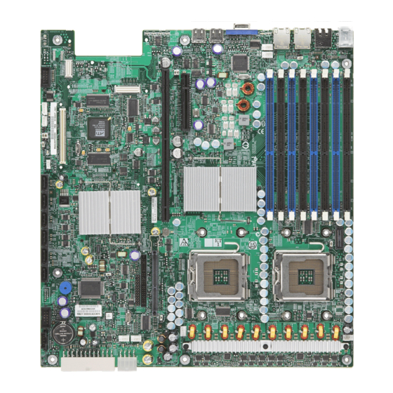
The following figure shows the board layout of the server board. Each connector and major component is identified by a number or letter, and a description is given below the figure. V U S TP02071 Revision 1.9 Intel order number: D31979-010... -
Page 15: Figure 1. Components & Connector Location Diagram
CPU #2 Fan Header 3-pin IPMB Header ® Bridge Board Connector Intel Local Control Panel Header ATA-100 Optical Drive Connector (Power+IO) Serial ‘A’ Header ® Intel RMM NIC Connector Figure 1. Components & Connector Location Diagram Revision 1.9 Intel order number: D31979-010... -
Page 16: Light Guided Diagnostic Led Locations
Post Code Diagnostic LEDs CPU Fault LED System Identification LED – Blue CPU Fault LED System Status LED – Green / Amber 5-Volt Stand-by Present DIMM Fault LEDs Figure 2. Light Guided Diagnostic LED Location Diagram Revision 1.9 Intel order number: D31979-010... -
Page 17: External I/O Connector Locations
PS/2 Mouse NIC port 2 (1 Gb) PS/2 Keyboard Video Serial Port B USB port 1 NIC port 1 (1 Gb) USB port 2 Figure 3. Intel® Server Board S5000PAL / S5000XAL ATX I/O Layout Revision 1.9 Intel order number: D31979-010... -
Page 18: Server Board Mechanical Drawings
Lotes B4L60BB2L 6012A0105401 8 x Ø 10.16 [0.400] 3 x 312.42 [12.300] 320.04 [12.600] 38.10 [1.500] Typ. TP02316 Figure 4. Intel® Server Board S5000PAL / S5000XAL – Hole and Component Positions (1 of 2) Revision 1.9 Intel order number: D31979-010... -
Page 19: Figure 5. Intel® Server Board S5000Pal / S5000Xal - Hole And Component Positions (2
230.38 [9.070] 231.89 [9.130] 243.83 [9.600] 265.41 [10.449] 297.84 [11.726] 298.51 [11.752] 308.74 [12.155] 309.042 [12.167] R1.52 [0.060] TP02292 Figure 5. Intel® Server Board S5000PAL / S5000XAL – Hole and Component Positions (2 of 2) Revision 1.9 Intel order number: D31979-010... -
Page 20: Figure 6. Intel® Server Board S5000Pal / S5000Xal - Restricted Areas On Side 1
4 x 7.62 [0.300] H < 9.5 mm [0.374"] Under Bridge Board REF ONLY H < 11 mm [0.433"] Under Heat Sink TP02293 Figure 6. Intel® Server Board S5000PAL / S5000XAL – Restricted Areas on Side 1 Revision 1.9 Intel order number: D31979-010... -
Page 21: Figure 7. Intel® Server Board S5000Pal / S5000Xal - Restricted Areas On Side 2
Limited Height 1.27 mm [0.05"] on Side 2 Limited Height 1.27 mm [0.05"] on Side 2, Dia. 29.5 mm [1.160"] 320.04 [12.600] TP02294 Figure 7. Intel® Server Board S5000PAL / S5000XAL – Restricted Areas on Side 2 Revision 1.9 Intel order number: D31979-010... - Page 22 298.51 [11.753] 5.52 [0.217] 4.83 [0.190] NO Components Allowed H < 27 mm [1.063"] 5.08 [0.200] Under Duct TP02295 Figure 8. Intel® Server Board S5000PAL / S5000XAL - Primary Side Duct and VR Restrictions Revision 1.9 Intel order number: D31979-010...
-
Page 23: Functional Architecture
Server Board S5000PAL / S5000XAL TPS Functional Architecture ® The architecture and design of the Intel® Server Board S5000PAL / S5000XAL is based on the Intel ® ® 5000 Chipset Family. The chipset is designed for systems based on the Dual-Core Intel Xeon processor 5000 sequence with system bus speeds of 667 MHz, 1066 MHz, and 1333 MHz. -
Page 24: Intel ® 5000P And 5000X Memory Controller Hubs (Mch)
This section will describe the general functionality of the memory controller hub as it is implemented on ® this server board. Depending on the version of the server board in use, it may support either the Intel ® 5000P MCH or the Intel 5000X MCH. -
Page 25: Memory Sub-System
3.1.3 Memory Sub-system On the Intel® Server Board S5000PAL / S5000XAL, the MCH provides four channels of Fully Buffered DIMM (FB-DIMM) memory. Each channel can support up to 2 Dual Ranked FB-DIMM DDR2 DIMMs. FB- DIMM memory channels are organized in to two branches for support of RAID 1 (mirroring). The MCH can support up to 8 DIMMs or a maximum memory size of 32 GB physical memory in non-mirrored mode and 16 GB physical memory in a mirrored configuration. -
Page 26: Figure 11. Memory Layout
17 GB/s for 533 and 21.0 GB/s for 667. On the Intel® Server Board S5000PAL / S5000XAL, a pair of channels becomes a branch where Branch 0 consists of channels A and B, and Branch 1 consists of channels C and D. FBD memory channels are organized into two branches for support of RAID 1(mirroring). -
Page 27: Table 2. Maximum 8 Dimm System Memory Configuration - X8 Single Rank
16 GB 32 GB Note: DDR2 DIMMs that are not fully buffered are NOT supported on this server board. See the Intel® Server Board S5000PAL / S5000XAL Tested Memory List for a complete list of supported memory for this server board. -
Page 28: Figure 12. Recommended Minimum Two Dimm Memory Configuration
Branch 1 TP02300 Figure 12. Recommended Minimum Two DIMM Memory Configuration Note: The server board supports single DIMM mode operation. Intel will only validate and support this configuration with a single 512MB x8 FBDIMM installed in DIMM slot A1. Revision 1.9... -
Page 29: Figure 13. Recommended Four Dimm Configuration
To upgrade a four DIMM mirrored memory configuration, four additional DIMMs must be added to the system. All four DIMMs in the second set must be identical to the first with the exception of speed. The MCH will adjust to the lowest speed DIMM. Revision 1.9 Intel order number: D31979-010... -
Page 30: Figure 14. Single Branch Mode Sparing Dimm Configuration
Channel B Channel C Channel D Branch 0 Branch 1 Intel® 5000P/5000X Memory Controller Hub Figure 14. Single Branch Mode Sparing DIMM Configuration • DIMM_A1 and DIMM_B1 must be identical in organization, size and speed. • DIMM_A2 and DIMM_B2 must be identical in organization, size and speed. -
Page 31: Snoop Filter (5000X Mch Only)
Universal Serial Bus 2.0 (USB) interface • Removable Media Drives • LPC bus interface • PC-compatible timer/counter and DMA controllers • APIC and 8259 interrupt controller • Power management • System RTC • General purpose I/O Revision 1.9 Intel order number: D31979-010... -
Page 32: Pci Sub-System
PE1: One x4 PCI Express* Bus Segment One x4 PCI Express* bus segment is directed through the ESB-2. This PCI Express segment, PE1, supports the optional Active SAS Midplane IOP as used in supported Intel chassis for this server board. 3.2.1.4 PE2: One x4 PCI Express* Bus Segment One x4 PCI Express* bus segment is directed through the ESB-2. - Page 33 ® The full height riser slot (J4F1) implements Intel Adaptive Slot Technology. This 280-pin connector is capable of supporting riser cards that meet either the PCI-X* or PCI Express* technology specifications.
-
Page 34: Serial Ata Support
See Figure 1. Components & Connector Location Diagram for the location of Intel RAID Activation Key connector location. Note: Availability of the Intel RAID Activation Key to support software RAID 5 will be deferred until after product launch of this server board. -
Page 35: Parallel Ata (Pata) Support
Embedded Server RAID Technology for SATA Option ROM provides a pre-OS user interface ® ® for the Intel Embedded Server RAID Technology implementation and provides the ability for an Intel Embedded Server RAID Technology volume to be used as a boot disk as well as to detect any faults in ® ®... -
Page 36: Table 5. Video Modes
BIOS Setup provides user options to configure the feature as follows. On-board Video Enabled Disabled Dual Monitor Video Shaded if on-board video is set to "Disabled" Enabled Disabled Revision 1.9 Intel order number: D31979-010... -
Page 37: Network Interface Controller (Nic)
3.4.2 MAC Address Definition Each Intel® Server Board S5000PAL / S5000XAL has four MAC addresses assigned to it at the Intel factory. During the manufacturing process, each server board will have a white MAC address sticker placed on the board. The sticker will display the MAC address in both bar code and alpha numeric formats. -
Page 38: Super I/O
3 and 4. Pin 1 on the jumper is identified by “*”. Note: By default, the rear RJ45 serial port is configured to support a DSR signal. This configuration is compatible with the Cisco* standard. Revision 1.9 Intel order number: D31979-010... -
Page 39: Figure 15. Serial Port Configuration Jumper Location
The following table provides the pin-out required for the adapter to provide RS232 support. A standard DH10-to-DB9 cable and 8-pin RJ45 to DB9 DCD and DSR adapters are available from Intel in the Serial Port Accessory Kit, product code: AXXRJ45DB92. - Page 40 LED. Refer to Figure 2. Light Guided Diagnostic LED Location Diagram for the location of the LEDs on the baseboard. The super I/O also provides PMW fan control to the system fans, monitors tach and presence signals for the system fans and monitors baseboard and control panel temperature. Revision 1.9 Intel order number: D31979-010...
-
Page 41: Platform Management
Server Management Bus (SMBUS) architecture used on this server board. See Appendix B for onboard sensor data. ® For more detailed platform management information, see the Intel S5000 Server Board Family Datasheet. Figure 16. SMBUS Block Diagram Revision 1.9... -
Page 42: Connector / Header Locations And Pin-Outs
JA8A1, JA8A2 External LAN 10/100/1000 connector with built-in magnetic SSI Control Panel J3H2 Header Internal USB J1J1 Header Intrusion detect J1C4 Header Serial ATA J1H1,J1G2,J1G1,J1F2,J1F1,J1E3 Header LCP / AUX IPMB J1C2 Header IPMB J1C3 Header Revision 1.9 Intel order number: D31979-010... -
Page 43: Power Connectors
Color Black Black Black Black +12Vdc Yellow/Black +12Vdc Yellow/Black +12Vdc Yellow/Black +12Vdc Yellow/Black Table 12. Power Supply Signal Connector Pin-out (J1K1) Signal Color SMB_CLK_ESB_FP_PWR_R Orange SMB_DAT_ESB_FP_PWR_R Black SMB_ALRT_3_ESB_R 3.3V SENSE- Yellow 3.3V SENSE+ Green Revision 1.9 Intel order number: D31979-010... -
Page 44: System Management Headers
Intel Remote Management Module. There is no support for third party ASMI cards on this server board. ® Note: This connector is NOT compatible for use with Intel Server Management Module Professional ® Edition (Product Code AXXIMMPRO) or the Intel Server Management Module Advanced Edition (Product Code AXXIMMADV). -
Page 45: Intel ® Rmm Nic Connector
The server board provides an internal 30-pin mezzanine style connector (J1B2) to accommodate a proprietary form factor RMM NIC module. The following table details the pin-out of the RMM NIC module connector. ® Table 14. 30-pin Intel RMM NIC Module Connector Pin-out (J1B2) Signal Name Signal Name... -
Page 46: Lcp/Aux Ipmb Header
BMC IMB 5V Standby Clock Line Riser Card Slots ® The server board has two riser card slots. The full height riser slot (J4F1) utilizes Intel Adaptive Slot Technology. It is capable of supporting riser cards that support either the PCI-X* or PCI Express* full height / full length add-in cards. -
Page 47: Table 18. Full-Height Riser Slot Pin-Out (J4F1)
PE5_MCH_RXP <3..0> FM_LP_RISER_TYPE1 PE5_MCH_RXN <3..0> FM_LP_RISER_TYPE0 Table 18. Full-height Riser Slot Pin-out (J4F1) Pin-Side B PCI Spec Signal Pin-Side A PCI Spec Signal Ground -12V 3.3VAux Wake# REFCLK2+ 3.3V REFCLK2+ PERST_N REFCLK1+ HSOp(0) REFCLK1+ HSOn(0) Revision 1.9 Intel order number: D31979-010... - Page 48 HSOn(4) HSIp(4) HSIn(4) HSOp(5) HSOn(6) HSIp(5) HSIn(5) HSOp(6) HSOn(6) HSIp(6) HSIn(6) HSOp(7) HSOn(7) HSIp(7) HSIn(7) INTB# INTD# ZCR_PRSNT_L Reserved ZCR_MSKID_L IOP INTA IOP INTB INTA# INTC# CLK3 REQ3# CLK2 GNT3# REQ2# RST# Reserved Reserved Revision 1.9 Intel order number: D31979-010...
- Page 49 +3.3V SERR# SMBD +3.3V SMBCLK C/BE[1]# Ground AD[14] Ground AD[15] AD[12] +3.3V AD[10] AD[13] M66EN AD[11] Ground Ground Ground AD[09] AD[08] C/BE[0]# AD[07] +3.3V +3.3V AD[06] AD[05] AD[04] AD[03] Ground Ground AD[02] AD[01] AD[00] Revision 1.9 Intel order number: D31979-010...
- Page 50 AD[49] Ground 3.3V AD[48] AD[47] AD[46] AD[45] Ground Ground AD[44] AD[43] AD[42] AD[41] 3.3V Ground AD[40] AD[39] AD[38] AD[37] Ground 3.3V AD[36] AD[35] AD[34] AD[33] Ground Ground AD[32] Type1 PXH_RST_N Type0 Ground Size PXH_PWROK Revision 1.9 Intel order number: D31979-010...
-
Page 51: Ssi Control Panel Connector
Server Board S5000PAL / S5000XAL TPS SSI Control Panel Connector The server board provides a 24-pin SSI control panel connector (J3H2) for use with non-Intel chassis. The following table provides the pin-out for this connector. Table 19. Front Panel SSI Standard 24-pin Connector Pin-out (J3H2) - Page 52 SMB_IPMB_ 5VSB_CLK SMB_SN_3V3SB_CLK_BUF LED_ HDD_ACTIVITY_N V_IO_HSYNC2_BUF_FP P3V3 V_IO_VSYNC2_BUF_FP FP_PWR_LED_N_R P3V3_STBY V_IO_BLUE_CONN_FP FP_ID_LED_R1_N V_IO_GREEN_CONN_FP FM_SIO_TEMP_SENSOR V_IO_RED_CONN_FP LED_FAN3_FAULT LED_FAN2_FAULT LED_FAN10_FAULT LED_FAN1_FAULT LED_FAN5_FAULT FAN_PWM_CPU1 LED_FAN4_FAULT FAN_IO_PWM FAN_PWM_CPU2 PCI_FAN_TACH9 PCI_FAN_TACH10 FAN_TACH7 FAN_TACH8 FAN_TACH5 FAN_TACH6 FAN_TACH3_H7 FAN_TACH4_H7 FAN_TACH1_H7 FAN_TACH2_H7 Revision 1.9 Intel order number: D31979-010...
-
Page 53: I/O Connector Pin-Out Definition
(JA8A1, JA8A2). The pin-out for each connector is identical and is defined in the following table. Table 22. RJ-45 10/100/1000 NIC Connector Pin-out (JA8A1, JA8A2) Signal Name P1V8_NIC NIC_A_MDI3P NIC_A_MDI3N NIC_A_MDI2P NIC_A_MDI2N NIC_A_MDI1P NIC_A_MDI1N NIC_A_MDI0P NIC_A_MDI0N 11 (D1) NIC_LINKA_1000_N (LED 12 (D2) NIC_LINKA_100_N (LED) 13 (D3) NIC_ACT_LED_N NIC_LINK_LED_N Revision 1.9 Intel order number: D31979-010... -
Page 54: Ide Connector
4 port SAS, dual Gb NIC, and Infiniband*. For more detail on the supported IO ® modules, please refer to the Intel Server Board S5000PAL / S5000XAL IO Module Hardware ® Specification. The following table details the pin-out of the Intel I/O Expansion Module connector. Revision 1.9 Intel order number: D31979-010... -
Page 55: Sata Connectors
® Connector / Header Locations and Pin-outs Intel Server Board S5000PAL / S5000XAL TPS ® Table 24. 50-pin Intel I/O Expansion Module Connector Pin-out (J3B1) Signal Name Signal Name P3V3_AUX P3V3_AUX PE_RST_G2_PM_N PE2_ESB_RXP_C<0> PE2_ESB_RXN_C<0> PE2_ESB_TXP_C<0> PE2_ESB_TXN_C<0> PE2_ESB_RXP_C<1> PE2_ESB_RXN_C<1> PE2_ESB_TXP_C<2> PE2_ESB_TXN_C<2>... -
Page 56: Serial Port Connectors
Keyboard Data TP_PS2_2 Test point – keyboard Ground P5V_KB_F Keyboard / mouse power KB_CLK_F Keyboard Clock TP_PS2_6 Test point – keyboard / mouse MS_DAT_F Mouse Data TP_PS2_8 Test point – keyboard / mouse Ground Revision 1.9 Intel order number: D31979-010... -
Page 57: Usb 2.0 Connectors
USBpower port 1 USB_ESB_P0N_CONN USB port 0 negative signal USB_ESB_P1N_CONN USB port 1 negative signal USB_ESB_P0P_CONN USB port 0 positive signal USB_ESB_P1P_CONN USB port 1 positive signal Ground Ground Ground Ground No Pin TP_USB_ESB_NC TEST POINT Revision 1.9 Intel order number: D31979-010... -
Page 58: Fan Headers
Note: Intel Corporation server baseboards support peripheral components and contain a number of high- density VLSI and power delivery components that need adequate airflow to cool. Intel’s own chassis are designed and tested to meet the intended thermal requirements of these components when the fully integrated system is used together. -
Page 59: Jumper Block Settings
If these pins are jumpered, the CMOS settings will be cleared immediately. These pins should not be jumpered for normal operation BMC Force Update Mode Disable Password Enable Reset J1D2 J1D1 Clear CMOS J1D3 TP02080 Figure 17. Recovery Jumper Blocks (J1D1, J1D2, J1D3) Revision 1.9 Intel order number: D31979-010... -
Page 60: Cmos Clear And Password Reset Usage Procedure
The CMOS Clear (J1D3) and Password Reset (J1D2) recovery features are designed so that the desired operation can be achieved with minimal system down time. The usage procedure for these two features ® has changed from previous generation Intel Server Boards. The following procedure outlines the new usage model. -
Page 61: Bios Select Jumper
To perform a normal BIOS update, follow the below steps: 1. Boot the system with the jumper covering pins 2 and 3. 2. Update the BIOS using iFlash or the Intel® One Flash Update (OFU) utility. 3. Reset the system. -
Page 62: External Rj45 Serial Port Jumper Block
The jumper block J8A3, located directly behind the external RJ45 serial port, is used to configure either a DSR or a DCD signal to the connector. J8A3 1-2: DCD to DTR 3-4: DSR to DTR (factory default) TP02303 Figure 19. External RJ45 Serial Port Configuration Jumper Revision 1.9 Intel order number: D31979-010... -
Page 63: Light Guided Diagnostics
Some of the features and components that require this voltage be ® present when the system is “Off” include the BMC within the ESB-2, onboard NICs, and optional Intel RMM. The LED located just below the system recovery jumper block labeled “5V STBY” is illuminated when AC power is applied to the platform and 5 Volt standby voltage is supplied to the server board by the power supply. -
Page 64: System Id Led And System Status Led
By issuing the appropriate hex IPMI “Chassis Identify” value, the ID LED will either blink blue for 15 seconds and turn off or will blink indefinitely until the appropriate hex IPMI Chassis Identify value is issued to turn it off. Revision 1.9 Intel order number: D31979-010... -
Page 65: System Status Led - Bmc Initialization
Once BMC initialization has completed, the status LED will stop blinking and the power button functionality is restored and can be used to turn on the server. Revision 1.9 Intel order number: D31979-010... -
Page 66: Dimm Fault Leds
The server board provides a memory fault LED for each DIMM slot. The DIMM fault LED is illuminated when the system BIOS disables the specified DIMM after it reaches a specified number of given failures ® or if specific critical DIMM failures are detected. See the Intel S5000 Series Chipsets Server Board Family Datasheet for more details. -
Page 67: Post Code Diagnostic Leds
POST process to be executed. See Appendix C for a complete description of how these LEDs are read, and for a list of all supported POST codes. TP02312 Figure 24. POST Code Diagnostic LED Location Revision 1.9 Intel order number: D31979-010... -
Page 68: Power And Environmental Specifications
VLSI and power delivery components that need adequate airflow to cool. Intel ensures through its own chassis development and testing that when Intel server building blocks are used together, the fully integrated system will meet the intended thermal requirements of these components. It is the... -
Page 69: Server Board Power Requirements
Note: These values are for reference only. The Dual-Core Intel Xeon processor 5000 sequence ® Datasheet contains the actual specifications for the processor. If the values found in the Dual-Core Intel ® ® processor 5000 sequence Datasheet are different than those published here, the Dual-Core Intel Xeon ®... -
Page 70: Power Supply Output Requirements
The contents of this section specify the power supply requirements Intel used to develop a power supply for its 1U server platform. The combined power of all outputs shall not exceed the rated output power of the power supply. The power supply must meet both static and dynamic voltage regulation requirements for the minimum loading conditions. -
Page 71: Grounding
- 5% / +5% +4.75 +5.00 +5.25 + 12V1,2,3,4 - 5% / +5% +11.40 +12.00 +12.60 - 12V - 5% / +9% -10.80 -12.00 -13.20 + 5VSB - 5% / +5% +4.75 +5.00 +5.25 Revision 1.9 Intel order number: D31979-010... -
Page 72: Dynamic Loading
1. The measurement shall be made across a 100 Ω resistor between each of the DC outputs, including ground, at the DC power connector and chassis ground (power subsystem enclosure). 2. The test set-up shall use an FET probe such as Tektronix* model P6046 or equivalent. Revision 1.9 Intel order number: D31979-010... -
Page 73: Ripple / Noise
) of each other during turn off. The following diagrams show the timing vout_off requirements for the power supply being turned on and off via the AC input with PSON held low, and the PSON signal with the AC input applied. Revision 1.9 Intel order number: D31979-010... -
Page 74: Figure 26. Output Voltage Timing
All main outputs must leave regulation within this msec vout_off time. The 5VSB output voltage rise time shall be from 1.0ms to 25.0ms V out 10% V out T vout_off T vout_rise T vout_on TP02313 Figure 26. Output Voltage Timing Revision 1.9 Intel order number: D31979-010... -
Page 75: Figure 27. Turn On/Off Timing (Power Supply Signals)
T sb_on_delay T pwok_on T pson_pwok PWOK T pwok_holdup T 5VSB_holdup T sb_vout 5 VSB T pson_on_delay PSON AC turn on/off cycle PSON turn on/off cycle TP02314 Figure 27. Turn On/Off Timing (Power Supply Signals) Revision 1.9 Intel order number: D31979-010... -
Page 76: Residual Voltage Immunity In Standby Mode
It also should not trip the power supply protection circuits during turn on. Residual voltage at the power supply outputs for a no load condition shall not exceed 100 mV when AC voltage is applied and the PSON# signal is de-asserted. Revision 1.9 Intel order number: D31979-010... -
Page 77: Regulatory And Certification Information
CE Declaration of Conformity International CB Certification – IEC60950 None Required CISPR 22 / CISPR 24 Korea RRL Certification MIC Notice No. 1997-41 (EMC) & 1997-42 (EMI) 인증번호: CPU-Model Name (A) Taiwan BSMI CNS13438 D33025 Revision 1.9 Intel order number: D31979-010... -
Page 78: Electromagnetic Compatibility Notices
Europe (CE Declaration of Conformity) This product has been tested in accordance too, and complies with the Low Voltage Directive (73/23/EEC) and EMC Directive (89/336/EEC). The product has been marked with the CE Mark to illustrate its compliance. Revision 1.9 Intel order number: D31979-010... -
Page 79: Bsmi (Taiwan)
English translation of the notice above: 1. Type of Equipment (Model Name): On License and Product 2. Certification No.: On RRL certificate. Obtain certificate from local Intel representative 3. Name of Certification Recipient: Intel Corporation 4. Date of Manufacturer: Refer to date code on product 5. -
Page 80: Product Ecology Compliance
Server Board S5000PAL / S5000XAL TPS Regulatory and Certification Information Product Ecology Compliance Intel has a system in place to restrict the use of banned substances in accordance with world wide product ecology regulatory requirements. The following is Intel’s product ecology compliance criteria. Compliance Regional... -
Page 81: Other Markings
Compliance Reference Description Marking Example Intel Internal All materials, parts and subassemblies must not Specification contain restricted materials as defined in Intel’s Environmental Product Content Specification of None Required Suppliers and Outsourced Manufacturers – http://supplier.intel.com/ehs/environmental.htm International ISO11469 - Plastic parts weighing >25gm are intended to be marked with per ISO11469. -
Page 82: Appendix A: Integration And Usage Tips
Intel® Server Board S5000PAL / S5000XAL Tested Memory List. For a list of Intel supported operating systems, add-in cards, and peripherals for this server board, see the Intel® Server Board S5000PAL / S5000XAL Tested Hardware and OS List. -
Page 83: Appendix B: Bmc Sensor Tables
Readable Offsets consists of the reading type offsets that do not generate events. Event Data This is the data that is included in an event message generated by the associated sensor. For threshold-based sensors, the following abbreviations are used: R: Reading value T: Threshold value Revision 1.9 Intel order number: D31979-010... - Page 84 Control Panel Status LED. Standby Some sensors operate on standby power. These sensors may be accessed and / or generate events when the main (system) power is off, but AC power is present. Revision 1.9 Intel order number: D31979-010...
-
Page 85: Table 43. Bmc Sensors
Redundancy – Trig Offset Redun- specific regained dancy Non-red: suff res from redund Redundancy Degraded lost Redundancy degraded Non-red: suff from insuff Non-red: Critical insufficient Redun degrade from full Redun degrade from non- redundant Revision 1.9 Intel order number: D31979-010... - Page 86 Event Sensor Log area reset / – Trig Offset Event Log Logging Specific cleared Disabled Session Session Audit Sensor 00h – Session – As defined Audit Specific activation by IPMI 01h – Session deactivation Revision 1.9 Intel order number: D31979-010...
- Page 87 R, T – defined BB 0.9V Voltage Threshold [u,l] [c,nc] Threshold As and De Analog R, T – defined BB Vbat Voltage Digital 01h – Limit Critical As and De – R, T Discrete exceeded Revision 1.9 Intel order number: D31979-010...
- Page 88 R, T – specific defined Fan 5B Chassis- Threshold [l] [c,nc] Threshold As and De Analog R, T – specific defined Fan 1 Chassis- Generic Device present As and De – – Present specific Revision 1.9 Intel order number: D31979-010...
- Page 89 As and De – – Present specific Chassis- Generic Redundancy – Trig Offset Redun- specific regained dancy Redundancy Degraded lost Redundancy degraded Non-red: suff res from redund Non-red: suff from insuff Non-red: Critical insufficient Revision 1.9 Intel order number: D31979-010...
- Page 90 As and De Analog R, T – Nozzle specific defined Power Supply 2 Power Chassis- Current Threshold [u] [c,nc] Threshold As and De Analog R, T – Gauge specific defined V1 rail (+12v) Power Supply 1 Revision 1.9 Intel order number: D31979-010...
- Page 91 State S5 / G2 G3 mechanical Button Button Sensor Power button – Trig Offset Specific Reset button SMI Timeout Digital 01h – State Critical As and De – Trig Offset – Timeout Discrete asserted Revision 1.9 Intel order number: D31979-010...
- Page 92 Threshold [u,l] [c,nc] Threshold As and De Analog R, T – Temp defined PCIe Link0 A0h Critical Sensor PCIe Bus correctable – See the – Interrupt Specific Link0 error BIOS EPS Degraded uncorrectable error Revision 1.9 Intel order number: D31979-010...
- Page 93 PCIe Bus correctable – See the – Interrupt Specific Link6 error BIOS EPS Degraded uncorrectable error PCIe Link7 A7h Critical Sensor PCIe Bus correctable – See the – Interrupt Specific Link7 error BIOS EPS Revision 1.9 Intel order number: D31979-010...
- Page 94 – See the – Link12 Interrupt Specific Link12 error BIOS EPS Degraded uncorrectable error PCIe Critical Sensor PCIe Bus correctable – See the – Link13 Interrupt Specific Link13 error BIOS EPS Degraded uncorrectable error Revision 1.9 Intel order number: D31979-010...
- Page 95 DIMM A1 Slot Sensor Fault status Degraded – Trig Offset – Connector Specific asserted Device installed OK Disabled Degraded Sparing DIMM A2 Slot Sensor Fault status Degraded – Trig Offset – Connector Specific asserted Revision 1.9 Intel order number: D31979-010...
- Page 96 DIMM D1 Slot Sensor Fault status Degraded – Trig Offset – Connector Specific asserted Device installed OK Disabled Degraded Sparing DIMM D2 Slot Sensor Fault status Degraded – Trig Offset – Connector Specific asserted Revision 1.9 Intel order number: D31979-010...
- Page 97 Trig Offset – Sparing Non-red: suff Degraded Redun- res from redund dancy Non-red: suff res from insuff Non-red: Insuff Critical B1 DIMM Entity Sensor Entity present – Trig Offset – Sparing Presence Specific Enabled Revision 1.9 Intel order number: D31979-010...
- Page 98 B01 DIMM Memory Discrete Fully redundant – Trig Offset – Mirroring Non-red:suff res Degraded Redun- from redund dancy Non-red:suff res from insuff res Non-red: insuff Critical Note 1: Not supported except for ESB-2 embedded NICs Revision 1.9 Intel order number: D31979-010...
-
Page 99: Appendix C: Post Code Diagnostic Led Decoder
ACh. Table 44: POST Progress Code LED Example LEDs Green Green Green Green Result Amber Green Diagnostic LEDs USB Port USB Port Back edge of baseboard Figure 28. Diagnostic LED Placement Diagram Revision 1.9 Intel order number: D31979-010... -
Page 100: Table 45. Diagnostic Led Post Code Decoder
Enabling the video controller (VGA) Remote Console 0x78h Resetting the console controller 0x79h Disabling the console controller 0x7Ah Enabling the console controller Keyboard (PS2 or USB) 0x90h Resetting the keyboard 0x91h Disabling the keyboard Revision 1.9 Intel order number: D31979-010... - Page 101 Reserved for initialization module use (PEIM) 0xE3h Reserved for initialization module use (PEIM) Driver Execution Environment (DXE) Core 0xE4h Entered EFI driver execution phase (DXE) 0xE5h Started dispatching drivers 0xE6h Started connecting drivers DXE Drivers Revision 1.9 Intel order number: D31979-010...
- Page 102 Crisis recovery has been initiated because of a user request 0x31h Crisis recovery has been initiated by software (corrupt flash) 0x34h Loading crisis recovery capsule 0x35h Handing off control to the crisis recovery capsule 0x3Fh Unable to complete crisis recovery. Revision 1.9 Intel order number: D31979-010...
-
Page 103: Appendix D: Post Error Messages And Handling
8306 Front panel controller locked Pause 8305 Hot swap controller failed Pause 84F2 Baseboard management controller failed to respond Pause 84F3 Baseboard management controller in update mode Pause 84F4 Sensor data record empty Pause Revision 1.9 Intel order number: D31979-010... - Page 104 Primary and secondary BIOS IDs do not match. Pause Override jumper is set to force boot from lower alternate BIOS bank of flash Pause 8601 8602 WatchDog timer expired (secondary BIOS may be bad!) Pause 8603 Secondary BIOS checksum fail Pause Revision 1.9 Intel order number: D31979-010...
-
Page 105: Table 47. Post Error Beep Codes
® ® Codes that are common across all Intel Server Boards and systems that use the Intel S5000 chipset are listed in Table 48. Each digit in the code is represented by a sequence of beeps whose count is equal to the digit. -
Page 106: Appendix E: Supported Intel Server Chassis
Server Board S5000PAL / S5000XAL TPS Appendix E: Supported Intel Server Chassis ® Appendix E: Supported Intel Server Chassis The Intel® Server Board S5000PAL / S5000XAL is supported in the following Intel high density rack mount server chassis: ® • Intel Server Chassis SR1500 ®... -
Page 107: Figure 30. 1U - Intel ® Server Chassis Sr1550 Overview
Power Distribution Board System Fan Bank 1+1 650 Watt Power Supply Mid-plane Board Modules (Active - SAS/SAS RAID shown) Intel® Server Board S5000PAL / Front Bezel (Optional; Standard Control Panel S5000XAL shown) ® Standard Control Panel or Intel Local Control... -
Page 108: Figure 31. 2U - Intel ® Server Chassis Sr2500 Overview
Five SATA/SAS Hard Drive Bays Modules Riser Card Assembly Slim-Line Optical Drive Bay System Memory Front Bezel (Optional) Mid-pane – Passive SAS/SATA or Active SAS/SAS RAID (Not shown) ® Figure 31. 2U – Intel Server Chassis SR2500 Overview Revision 1.9 Intel order number: D31979-010... -
Page 109: Glossary
Hertz (1 cycle/second) Inter-Integrated Circuit Bus ® Intel Architecture Input Buffer I/O Controller Hub ICMB Intelligent Chassis Management Bus IERR Internal Error I/O and Firmware Bridge INTR Interrupt Internet Protocol IPMB Intelligent Platform Management Bus Revision 1.9 Intel order number: D31979-010... - Page 110 System Event Log Server Input/Output Server Management Interrupt (SMI is the highest priority nonmaskable interrupt) Server Management Mode Server Management Software SNMP Simple Network Management Protocol To Be Determined Thermal Interface Material UART Universal Asynchronous Receiver/Transmitter Revision 1.9 Intel order number: D31979-010...
- Page 111 ® Glossary Intel Server Board S5000PAL / S5000XAL TPS Term Definition User Datagram Protocol UHCI Universal Host Controller Interface Universal time coordinate Voltage Identification Voltage Regulator Down Word 16-bit quantity Zero Insertion Force Revision 1.9 Intel order number: D31979-010...
-
Page 112: Reference Documents
ERP 2U – Rev. 2.31 – Entry Redundant Power Supply 2U form factor – Intel S5000 Server Board Family Note: Yellow Cover documents can only be obtained under NDA with Intel and ordered through an Intel representative. Revision 1.9 Intel order number: D31979-010...