
Related Manuals for Intel S3420GPRX


Summary of Contents for Intel S3420GPRX
- Page 1 ® Intel Server Board S3420GPRX User Guide A Guide for Technically Qualified Assemblers of Intel® Identified Subassemblies/Products Intel Order Number E90566-002...
- Page 2 Intel products are not designed, intended or authorized for use in any medical, life saving, or life sustaining applications or for any other application in which the failure of the Intel product could create a situation where personal injury or death may occur.
-
Page 3: Safety Information
Safety Information Important Safety Instructions Read all caution and safety statements in this document before performing any of the instructions. See also Intel Server Boards and Server Chassis Safety Information on the ® Intel Server Deployment Toolkit CD and/or at http://www.intel.com/support/... - Page 4 Intel® Server Board S3420GPRX User Guide...
-
Page 5: Warnings
Take care to grip with, but not squeeze, the pliers or other tool you use to remove a jumper, or you may bend or break the pins on the board. Intel® Server Board S3420GPRX User Guide... -
Page 6: Preface
Intel® Server Board S3420GPRX User Guide. For the latest version of this manual, see http://support.intel.com/support/motherboards/server/S3420GP/. -
Page 7: Additional Information And Software
Processor, memory DIMMs, hard drive, floppy drive, CD-ROM or DVD-ROM drive, RAID controller, operating system. For information about which accessories, memory, processors, and third-party hardware were tested and can be used with your board, and for ordering information for Intel products, see http://www.intel.com/support/motherboards/server/S3420GP/ compat.htm. - Page 8 Software and Drivers section for the most current BIOS, FRU/SDR, firmware, drivers, and utilities. For diagnostics test Diagnostics software ® See also the Intel Server Deployment Toolkit CD that came with your server board. Intel® Server Board S3420GPRX User Guide...
-
Page 9: Table Of Contents
Preparing for the Upgrade ...................15 Upgrading the BIOS ....................16 Recovering the BIOS ....................16 Recovering the BIOS ......................17 Clearing the Password ......................18 Updating the Integrated BMC ..................19 Chapter 3: Hardware Installations and Upgrades ..........21 Intel® Server Board S3420GPRX User Guide... - Page 10 Power Light Does Not Light ..................58 No Characters Display on Screen ................59 Characters Are Distorted or Incorrect ................. 59 System Cooling Fans Do Not Rotate Properly ............60 Drive Activity Light Does Not Light ................60 Intel® Server Board S3420GPRX User Guide...
- Page 11 Devices are not Recognized under Device Manager (Microsoft Windows* Operating Sys- tem) ........................63 Hard Drive(s) are not Recognized ................63 Bootable CD-ROM Disk Is Not Detected ..............64 LED Information ......................64 BIOS POST Beep Codes ....................65 Intel® Server Board S3420GPRX User Guide xiii...
- Page 12 Figure 18. Removing the PCI Riser Assembly from the Server System ......... 29 Figure 19. Installing a PCI Card in a Riser Card ..............29 Figure 20. Replacing the Backup Battery................31 Figure 21. POST Code Diagnostic LED Location ..............33 Intel® Server Board S3420GPRX User Guide...
- Page 13 Table 7. POST Progress Code LED Example .................34 Table 8. Diagnostic LED POST Code Decoder ...............34 Table 9. Product Certification Markings ..................50 Table 10. Resetting the System ....................55 Table 11. LED Information ......................64 Table 12. POST Error Beep Codes ..................65 Intel® Server Board S3420GPRX User Guide xvii...
-
Page 14: Chapter 1: Server Board Features
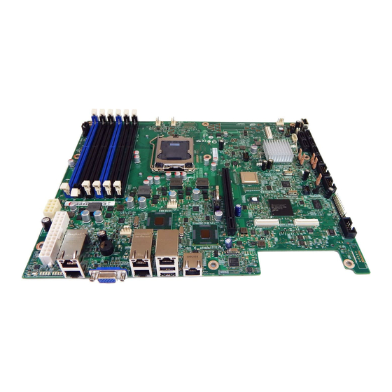
Server Board Features ® This chapter briefly describes the main features of the Intel Server Board S3420GPRX. This chapter provides a photograph of the product, list of the server board features, and diagrams showing the location of important components and connections on the server board. -
Page 15: Table 2. Server Board Features
Five 10/100/1000 Base-TX RJ45 LAN connector Internal connections: • Two USB 2x5 pin headers, each supporting two USB 2.0 ports • ® One USB 2x5 pin header for Intel USB SSD • One USB 2.0 internal vertical connector • One 2x5 Serial Port B header •... -
Page 16: Connector And Header Locations
Support for six Serial ATA II hard drives through six on-board Drive Support SATA II connectors with SW RAID 0, 1, 5, and 10. • Optical devices are supported • ® Up to four SAS hard drives through optional Intel SAS Entry RAID Module card • ® RAID Support Intel Embedded Server RAID Technology II through onboard SATA connectors provides SATA RAID 0, 1, and 10. - Page 17 RJ-45 Serial port Connector RJ-45 GbE(NIC5) and Dual IPMB Connector USB combo connector Dual port RJ-45 GbE LAN SATA SGPIO Connector Connector (NIC3 and NIC4) SATA RAID key HSBP Connector DB15 Video port AA. USB Floppy Intel® Server Board S3420GPRX User Guide...
-
Page 18: Configuration Jumpers
CPU Socket Figure 2. Server Board Connector and Component Locations Configuration Jumpers The server board has several jumper blocks that can be used to configure, protect, or recover specific features of the server board. Intel® Server Board S3420GPRX User Guide... - Page 19 EFI-bootable recovery media with the recovery BIOS image. J1E1: BMC Force Update Integrated BMC Firmware Force Update Mode – Disabled (Default) Integrated BMC Firmware Force Update Mode – Enabled Intel® Server Board S3420GPRX User Guide...
-
Page 20: Server Board Rear I/O Layout
Dual port RJ-45 GbE LAN Connector RJ-45 Serial Port (NIC1 and NIC2) Figure 4. Server Board Rear I/O Layout The NIC LEDs on the NIC connector are marked as A and B. The following table provides the LED information. Intel® Server Board S3420GPRX User Guide... -
Page 21: Raid Support
Matrix RAID – Intel Matrix Storage Technology RAID supports RAID 0/1/5/ ® Note: For help with navigating the BIOS Setup utility, see the Intel Server Board S3420GPRX Technical Product Specification. For information on how to configure RAID, refer to the RAID software user's guide at: http://www.intel.com/support/motherboards/server/S3420GPRX/howto.htm... -
Page 22: Processor
3400 series with up to ® ® 95W Thermal Design Power (TDP) with 2.5 GT/s or one Intel series with up to 73W Thermal Design Power (TDP) with 2.0GT/s. For a complete list of supported processors, see the links under “Additional Information and... -
Page 23: Power Supply
Optional Hardware ® Intel SAS Entry RAID Module AXX4SASMOD ® The Intel Server Board S3420GPRX provides a SAS module slot (J2H1) for the ® installation of an optional Intel SAS Entry RAID Module AXX4SASMOD. Once the ® optional Intel SAS Entry RAID Module AXX4SASMOD is present, the x4 PCI Express* links from PCI Express* x2 switch to the SAS module slot. -
Page 24: Figure 5. Intel ® Sas Entry Raid Module
The Intel Embedded Server RAID Technology II (Intel ESRTII) feature provides ® RAID modes 0, 1, and 10. If RAID 5 is needed with Intel ESRTII, you must install the ® optional Intel RAID Activation Key AXXRAKSW5 accessory. This activation key is ®... -
Page 25: Intel Remote Management Module 3 Lite
SAS Module AXX4SASMOD when a cable is attached between this connector and the backplane or I2C interface. ® Note: For help with navigating the BIOS Setup utility, refer to the Intel Server Board S3420GPRX Technical Product Specification. -
Page 26: Chapter 2: Server Utilities
A user must have adequate security rights to change these parameters. If a value cannot be changed for any reason, the feature's value field is inaccessible. Intel® Server Board S3420GPRX User Guide... -
Page 27: Table 5. Setup Menu Key Use
If "No" is selected and the <Enter> key is pressed, or if the <Esc> key is pressed, the user is returned to where they were before <F9> was pressed without affecting any existing field values. Intel® Server Board S3420GPRX User Guide... -
Page 28: Upgrading The Bios
Press <F2> Key if you want to run SETUP 2. Write down the current settings in the BIOS Setup program. Note: Do not skip step 2. You need these settings to configure your computer at the end of the procedure. Intel® Server Board S3420GPRX User Guide... -
Page 29: Upgrading The Bios
Note: During the recovery mode, video is not initialized. One high-pitched beep announces the start of the recovery process. The entire process takes two to four minutes. A successful update ends with two high-pitched beeps. Failure is indicated by a long series of short beeps. Intel® Server Board S3420GPRX User Guide... -
Page 30: Recovering The Bios
1 and 2. 9. Plug the system into the AC power source and power it up to confirm the recovery was successful. 10. Do NOT interrupt the BIOS POST during the first boot. Intel® Server Board S3420GPRX User Guide... -
Page 31: Clearing The Password
RAM. The CMOS Clear jumper is located on jumper block J1F5 on the server board. 1. Power down the system and disconnect the AC power. 2. Open the server chassis. For instructions, see your server chassis documentation. Intel® Server Board S3420GPRX User Guide... -
Page 32: Updating The Integrated Bmc
When performing the standard Integrated BMC firmware update procedure, the update utility places the Integrated BMC into an update mode, allowing the firmware to load safely onto the flash device. In the unlikely event the Integrated BMC firmware update Intel® Server Board S3420GPRX User Guide... - Page 33 9. Move jumper from the enabled position (covering pins 2 and 3) to the disabled position (covering pins 1 and 2). 10. Close the server chassis. 11. Reconnect the AC cord and power up the server. Intel® Server Board S3420GPRX User Guide...
-
Page 34: Chapter 3: Hardware Installations And Upgrades
2. Turn off all peripheral devices connected to the server. 3. Turn off the server. 4. Disconnect the AC power cord from the server. 5. Remove the server's cover and locate the DIMM sockets (see letters “A” to “E” Figure 10). Intel® Server Board S3420GPRX User Guide... -
Page 35: Removing Dimms
6. Gently spread the retaining clips at each end of the socket. The DIMM will lift from the socket. 7. Holding the DIMM by the edges, lift it from the socket, and store it in an anti-static package. Intel® Server Board S3420GPRX User Guide... -
Page 36: Installing The Processor
2. Turn off all peripheral devices connected to the server. Turn off the server. 3. Disconnect the AC power cord from the server. 4. Remove the server's cover. See the documentation that came with your server chassis for instructions on removing the server's cover. Intel® Server Board S3420GPRX User Guide... -
Page 37: Figure 11. Lifting The Load Lever
5. Locate the processor socket and open the socket lever (see Figure 11). AF003186 Figure 11. Lifting the Load Lever 6. Open the load plate (see letter “A” and “B” in Figure 12). AF003187 Figure 12. Open the Load Plate Intel® Server Board S3420GPRX User Guide... -
Page 38: Figure 13. Remove The Socket Protective Cover
8. Take the processor out of the box and remove the protective shipping cover (Figure 14). AF003189 Figure 14. Remove the Processor Protective Cover 9. Align the processor cutouts to match the two socket pins, and insert the processor into the socket as shown in Figure Intel® Server Board S3420GPRX User Guide... -
Page 39: Figure 15. Installing The Processor
16), close the socket lever, and ensure the load plate tab engages under the socket lever when fully closed (see letter “B” and “C” in Figure 16). AF003191 Figure 16. Close the Load Plate and Socket Lever Intel® Server Board S3420GPRX User Guide... -
Page 40: Installing The Heatsink(S)
Figure 16. Do not fully tighten one screw before tightening another. 5. Gradually and equally tighten each captive screw in the same order until each is firmly tightened. Figure 17. Installing the Heatsink Assembly Intel® Server Board S3420GPRX User Guide... -
Page 41: Removing A Processor
Note: You must attach add-in cards to a riser card when the riser card is removed from the chassis. 1. Remove the screw that attaches the PCI bracket shield to the rear of the chassis to remove the shield. Retain the screw. Intel® Server Board S3420GPRX User Guide... -
Page 42: Figure 18. Removing The Pci Riser Assembly From The Server System
Caution: Press the riser card straight down into the slot. Tipping it in the slot while installing it may damage the riser card or slot on the server board. 4. Use the screw removed in Step 1 to secure the riser card assembly to the chassis. Intel® Server Board S3420GPRX User Guide... -
Page 43: Replacing The Backup Battery
Varning: Explosionsfara vid felaktigt batteribyte. Använd samma batterityp eller en ekvivalent typ som rekommenderas av apparattillverkaren. Kassera använt batteri enligt fabrikantens instruktion. Varoitus: Paristo voi räjähtää, jos se on virheellisesti asennettu. Vaihda paristo ainoastaan laitevalmistajan suosittelemaan tyyppiin. Hävitä käytetty paristo valmistajan ohjeiden mukaisesti. Intel® Server Board S3420GPRX User Guide... -
Page 44: Figure 20. Replacing The Backup Battery
8. Remove the new lithium battery from its package, and, being careful to observe the correct polarity, insert it in the battery socket. 9. Close the chassis. 10. Run Setup to restore the configuration settings to the RTC. Intel® Server Board S3420GPRX User Guide... - Page 45 Intel® Server Board S3420GPRX User Guide...
-
Page 46: Appendix A: Led Decoder
Diagnostic LED #1 Diagnostic LED #0 (LSB LED) Table 6. Diagnostic LED Placement Diagram In the following example, the BIOS sends a value of ACh to the diagnostic LED decoder. The LEDs are decoded as follows: Intel® Server Board S3420GPRX User Guide... -
Page 47: Table 7. Post Progress Code Led Example
Lower Nibble Host Processor 0x10h Power-on initialization of the host processor (bootstrap processor) 0x11h Host processor cache initialization (including AP) 0x12h Starting application processor initialization 0x13h SMM initialization Chipset 0x21h Initializing a chipset component Memory Intel® Server Board S3420GPRX User Guide... - Page 48 Detecting presence of memory 0x24h Programming timing parameters in the memory controller 0x25h Configuring memory parameters in the memory controller 0x26h Optimizing memory controller settings 0x27h Initializing memory, such as ECC init 0x28h Testing memory Intel® Server Board S3420GPRX User Guide...
- Page 49 Reserved for SMBUS Local Console 0x70h Resetting the video controller (VGA) 0x71h Disabling the video controller (VGA) 0x72h Enabling the video controller (VGA) Remote Console 0x78 Resetting the console controller 0x79 Disabling the console controller Intel® Server Board S3420GPRX User Guide...
- Page 50 Removable Media 0xB8 Resetting the removable media device 0xB9 Disabling the removable media device 0xBA Detecting the presence of a removable media device (CD-ROM detection, etc.) 0xBC Enabling / configuring a removable media device Intel® Server Board S3420GPRX User Guide...
- Page 51 Driver Execution Environment (DXE) Core (not accompanied by a beep code) 0xE4 Entered EFI driver execution phase (DXE) 0xE5 Started dispatching drivers 0xE6 Started connecting drivers DXE Drivers (not accompanied by a beep code) Intel® Server Board S3420GPRX User Guide...
- Page 52 0x31 Crisis recovery has been initiated by software (corrupt flash) 0x34 Loading crisis recovery capsule 0x35 Handing off control to the crisis recovery capsule 0x3F Unable to complete crisis recovery Intel® Server Board S3420GPRX User Guide...
- Page 53 0xEBh Memory Test Error: Memory failed Hardware BIST. 0xEDh Population Error: RDIMMs and UDIMMs cannot be mixed in the system. 0xEEh Mismatch Error: More than two Quad-Ranked DIMMS in a channel. Intel® Server Board S3420GPRX User Guide...
-
Page 54: Appendix B: Intel Server Issue Report Form
- can be found on the white sticker label on the baseboard System BIOS Version: ® Intel Remote Management Module Firmware Version (if applicable): ® Intel Management Module BMC Revision (if applicable): BMC/mBMC Version: FRU/SDR Version: HSC Version: Has the latest BIOS been tried? (Yes/No): Intel® Server Board S3420GPRX User Guide... - Page 55 Thermal Solution Processor 1 Processor 2 Processor 3 Processor 4 Thermal solution (Heatsink) examples: (1U, Passive w/air ducting, Active w/fan, etc.) =============================================================== Memory: Manufacturer Part Number DRAM Part Number On Intel tested list? Intel® Server Board S3420GPRX User Guide...
- Page 56 =============================================================== Operating System Information (Example: RedHat* Enterprise Linux, Microsoft* Windows* Server 2003, Service pack 1, OEM CD): Manufacturer: Version: Language version (English, Arabic, Chinese (Simplified)): Service Pack Level or Kernel Revision: Distribution (OEM/Retail): =============================================================== Intel® Server Board S3420GPRX User Guide...
- Page 57 Has the latest RAID driver been tried? (Yes/No): RAID volumes configuration (disks & RAID level): RAID volume use (Boot device/Data Volume): Is BBU (Battery Backup Unit) installed? (Yes/No): BBU part number: =============================================================== Detailed description of issue: Troubleshooting tried: Intel® Server Board S3420GPRX User Guide...
- Page 58 =============================================================== Issue impact statements: Do you have any potential Intel system, or component purchases that this issue is holding up? If yes, please provide a brief description below. Do you have systems already purchased that are not being delivered to your customers because of this issue? If yes, please provide a brief description below.
- Page 59 Intel® Server Board S3420GPRX User Guide...
-
Page 60: Appendix C: Getting Help
— A searchable knowledgebase to search for product information throughout the support site 2. If you are still unable to obtain a solution to your issue, send an email to Intel’s technical support center using the online form available at http://supportmail.intel.com/scripts-emf/welcome.aspx... - Page 61 Intel® Server Board S3420GPRX User Guide...
-
Page 62: Appendix D: Regulatory And Compliance Information
BSMI Declaration of Conformity (Taiwan) Product EMC Compliance - Class A Compliance Note: Legally this product is required to comply with Class A emission requirements because it is intended for a commercial type market place. Intel targets 10db margin to Class A Limits. ®... -
Page 63: Certifications / Registrations / Declarations
This product is marked with the following Product Certification Markings: Table 9. Product Certification Markings Regulatory Region Marking Compliance UL Mark USA/Canada CE Mark Europe EMC Marking (Class A) Canada CANADA ICES-003 CLASS A BSMI Marking (Class A) Taiwan D33025 Intel® Server Board S3420GPRX User Guide... -
Page 64: Electromagnetic Compatibility Notices
This device complies with Part 15 of the FCC Rules. Operation is subject to the following two conditions: (1) this device may not cause harmful interference, and (2) this device must accept any interference received, including interference that may cause undesired operation. Intel® Server Board S3420GPRX User Guide... -
Page 65: Ices-003 (Canada)
This digital apparatus does not exceed the Class A limits for radio noise emissions from digital apparatus set out in the interference-causing equipment standard entitled: “Digital Apparatus,” ICES-003 of the Canadian Department of Communications. Intel® Server Board S3420GPRX User Guide... -
Page 66: Europe (Ce Declaration Of Conformity)
KCC (Korea) English translation of the notice above: 1. Type of Equipment (Model Name): On License and Product 2. Certification No.: On RRL certificate. Obtain certificate from local Intel representative 3. Name of Certification Recipient: Intel Corporation 4. Date of Manufacturer: Refer to date code on product 5. -
Page 67: Restriction Of Hazardous Substances (Rohs) Compliance
Restriction of Hazardous Substances (RoHS) Compliance Intel has a system in place to restrict the use of banned substances in accordance with world wide product ecology regulatory requirements. Suppliers Declarations of Conformity to the banned substances must be obtained from all suppliers; and a Material Declaration Data Sheet (MDDS) must be produced to illustrate compliance. -
Page 68: Appendix E: Troubleshooting
In addition to the server firmware and files, also update any drivers used for components you installed in your system, such as video drivers, network drivers, and SCSI drivers. Intel provides a package called the "Platform Confidence Test" that may help with your diagnostics. See “Additional Information and Software”... -
Page 69: Problems Following Initial System Installation
Are all integrated components from the tested components lists? Check the tested memory, and chassis lists, as well as the supported hardware and operating system list. See “Additional Information and Software” for links to the tested component lists. Intel® Server Board S3420GPRX User Guide... -
Page 70: Hardware Diagnostic Testing
Once the system boots up, the operating system prompt displays on the screen. The prompt varies according to the operating system. If the operating system prompt does not display, see “No Characters Display on Screen”. Intel® Server Board S3420GPRX User Guide... -
Page 71: Specific Problems And Corrective Actions
Remove the processor(s) and re-seat them. • Make sure the chassis standoffs are installed only below mounting holes. Misplaced standoffs can contact the pins on the bottom of the server board and cause a short. Intel® Server Board S3420GPRX User Guide... -
Page 72: No Characters Display On Screen
Are the brightness and contrast controls properly adjusted on the video monitor? See the manufacturer's documentation. • Are the video monitor's signal and power cables properly installed? • Does this video monitor work correctly if plugged into a different system? Intel® Server Board S3420GPRX User Guide... -
Page 73: System Cooling Fans Do Not Rotate Properly
CD-ROM Drive or DVD-ROM Drive Activity Light Does Not Light Check the following: • Are the CD-ROM/DVD-ROM drive's power and signal cables properly installed? • Are all relevant switches and jumpers on the drive set correctly? • Is the drive properly configured? Intel® Server Board S3420GPRX User Guide... -
Page 74: Cannot Connect To A Server
Make sure the cable is connected to the port from the on-board network controller. • Make sure your BIOS is current. Refer to the “Additional Information and Software” for a link to the current version. Intel® Server Board S3420GPRX User Guide... -
Page 75: System Boots When Installing Pci Card
If you are running the software from a floppy disk, CD-ROM or DVD-ROM, try a different disk. • Make sure the correct device drivers installed. If the problems persist, contact the software vendor's customer service representative. Intel® Server Board S3420GPRX User Guide... -
Page 76: Problems With Application Software That Ran Correctly Earlier
Devices are not Recognized under Device Manager (Microsoft Windows* Operating System) ® The Microsoft Windows* operating systems do not include all of the drivers for the Intel chipsets, onboard NICs, and other components. See “Additional Information and Software”... -
Page 77: Bootable Cd-Rom Disk Is Not Detected
Identify the power state Front panel Green Off = Power is off (off or of the system • On = Power on or S0) • Slow Blink = Low power state (S1 - S3) Intel® Server Board S3420GPRX User Guide... -
Page 78: Bios Post Beep Codes
The user can override this option by setting the POST Error Pause option as disabled on the BIOS setup Main screen. If this option is disabled, the system boots the operating system without user intervention. The default is disabled. Intel® Server Board S3420GPRX User Guide...