Table of Contents
Advertisement
Intel® Next Unit of Computing
Board D33217GKE
Technical Product Specification
October 2012
Order Number: G67686-002
The Intel Next Unit of Computing Board D33217GKE may contain design defects or errors known as errata that may cause the product to deviate from
published specifications. Current characterized errata are documented in the Intel Next Unit of Computing Board D33217GKE Specification Update.
Advertisement
Table of Contents

Related Manuals for Intel D33217GKE


Summary of Contents for Intel D33217GKE
- Page 1 Order Number: G67686-002 The Intel Next Unit of Computing Board D33217GKE may contain design defects or errors known as errata that may cause the product to deviate from published specifications. Current characterized errata are documented in the Intel Next Unit of Computing Board D33217GKE Specification Update.
-
Page 2: Revision History
Intel Next Unit of Computing Boards may contain design defects or errors known as errata, which may cause the product to deviate from published specifications. Current characterized errata are available on request. -
Page 3: Board Identification Information
Board Identification Information ® Basic Intel Next Unit of Computing Board D33217GKE Identification Information AA Revision BIOS Revision Notes G69901-200 GKPPT10H.86A.0020 G69901-201 GKPPT10H.86A.0020 Notes: The AA number is found on a small label on the component side of the board. - Page 4 Intel Desktop Board D33217GKE Technical Product Specification...
-
Page 5: Preface
Computing Board D33217GKE. Intended Audience The TPS is intended to provide detailed, technical information about Intel Next Unit of Computing Board D33217GKE and its components to the vendors, system integrators, and other engineers and technicians who need this level of information. It is specifically not intended for general audiences. - Page 6 Intel Desktop Board D33217GKE Technical Product Specification Other Common Notation Used after a signal name to identify an active-low signal (such as USBP0#) Gigabyte (1,073,741,824 bytes) GB/s Gigabytes per second Gb/s Gigabits per second Kilobyte (1024 bytes) Kilobit (1024 bits)
-
Page 7: Table Of Contents
1.2 Online Support ................. 18 1.3 Processor ..................18 1.4 System Memory ................19 1.4.1 Memory Configurations ............20 ® 1.5 Intel QS77 Express Chipset .............. 22 1.5.1 Direct Media Interface (DMI) ..........22 1.5.2 Display Interfaces ..............22 1.6 Graphics Subsystem ................. 22 1.6.1... - Page 8 Intel Desktop Board D33217GKE Technical Product Specification 2 Technical Reference 2.1 Memory Resources ................35 2.1.1 Addressable Memory ............. 35 2.1.2 Memory Map ................. 37 2.2 Connectors and Headers ..............37 2.2.1 Back Panel Connectors ............38 2.2.2 Connectors and Headers (Bottom) ........... 39 2.3 BIOS Setup Configuration Jumper ............
- Page 9 Contents 5.1.5 ENERGY STAR* 5.2, e-Standby, and ErP Compliance ....78 5.1.6 Regulatory Compliance Marks (Board Level) ......79 5.2 Battery Disposal Information .............. 80 Figures Major Board Components (Top) ............13 Major Board Components (Bottom) ............. 15 Block Diagram .................. 17 Memory Channel and SO-DIMM Configuration ........
- Page 10 Intel Desktop Board D33217GKE Technical Product Specification Tables Feature Summary ................11 Components Shown in Figure 1 ............14 Components Shown in Figure 2 ............16 Supported Memory Configurations ............19 LAN Connector LED States ..............27 Effects of Pressing the Power Switch ........... 30 Power States and Targeted System Power ...........
-
Page 11: Product Description
Intel QS77 Express Chipset consisting of the Intel QS77 Express Platform Chipset Controller Hub (PCH) ® • Integrated graphics support for processors with Intel Graphics Technology: Graphics ― Two High Definition Multimedia Interface* (HDMI*) back panel connectors ® Audio Intel High Definition Audio via the HDMI v1.4a interfaces... - Page 12 Intel Desktop Board D33217GKE Technical Product Specification Table 2. Feature Summary (continued) ® Gigabit (10/100/1000 Mb/s) LAN subsystem using the Intel 82579V Gigabit LAN Support Ethernet Controller Hardware Monitor Hardware monitoring subsystem, based on a Nuvoton NPCE791C embedded Subsystem controller, including: •...
-
Page 13: Board Layout (Top)
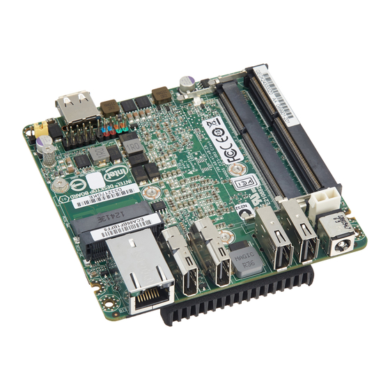
Product Description 1.1.2 Board Layout (Top) Figure 1 shows the location of the major components on the top-side of Intel Next Unit of Computing Board D33217GKE. Figure 1. Major Board Components (Top) -
Page 14: Components Shown In Figure 1
Intel Desktop Board D33217GKE Technical Product Specification Table 3 lists the components identified in Figure 1. Table 3. Components Shown in Figure 1 Item from Figure 1 Description Battery Standby power LED Processor fan header Onboard power button Power LED... -
Page 15: Board Layout (Bottom)
Product Description 1.1.3 Board Layout (Bottom) Figure 2 shows the location of the major components on the bottom-side of Intel Next Unit of Computing Board D33217GKE. Figure 2. Major Board Components (Bottom) -
Page 16: Components Shown In Figure 2
Intel Desktop Board D33217GKE Technical Product Specification Table 4. Components Shown in Figure 2 Item from Figure 2 Description Back panel connectors PCI Express Full-Mini Card connector PCI Express Half-Mini Card connector Front panel dual-port USB 2.0 header BIOS setup configuration jumper Front panel USB 2.0 connector... -
Page 17: Block Diagram
Product Description 1.1.4 Block Diagram Figure 3 is a block diagram of the major functional areas of the board. Figure 3. Block Diagram... -
Page 18: Online Support
025414.htm Integration information http://www.intel.com/support/go/buildit Processor The board has a soldered-down Intel Core i3-3217U processor with Integrated Graphics Technology and integrated memory controller. NOTE This board has specific requirements for providing power to the processor. Refer to Section 2.5.1 on page 49 for information on power supply requirements for this board. -
Page 19: System Memory
Product Description System Memory The board has two 204-pin SO-DIMM sockets and supports the following memory features: • 1.5 V DDR3 SDRAM SO-DIMMs with gold plated contacts • Support for 1.35 V Low Voltage DDR3 (new JEDEC specification) Two independent memory channels with interleaved mode support •... -
Page 20: Memory Configurations
Intel Desktop Board D33217GKE Technical Product Specification For information about… Refer to: Tested Memory http://support.intel.com/support/motherboards/desktop/sb /CS-025414.htm 1.4.1 Memory Configurations The processor supports the following types of memory organization: Dual channel (Interleaved) mode. This mode offers the highest throughput for •... -
Page 21: Memory Channel And So-Dimm Configuration
Product Description Figure 4 illustrates the memory channel and SO-DIMM configuration. Figure 4. Memory Channel and SO-DIMM Configuration... -
Page 22: Intel ® Qs77 Express Chipset
PCH. The display data from the frame buffer is processed in the display engine of the processor and sent to the PCH over the Intel FDI where it is transcoded as per the display protocol and driven to the display monitor. - Page 23 High-Definition content at up to 1080p resolution Hardware accelerated MPEG-2, VC-1/WMV and H.264/AVC Hi-Definition video formats Intel HD Technology with Advanced Hardware Video Transcoding Blu-ray* S3D via HDMI 1.4a Dynamic Video Memory Technology (DVMT) 5.0 support ...
-
Page 24: Usb
Windows operating systems. 1.7.1 AHCI Mode The board supports AHCI storage mode via the Intel QS77 Express Chipset. NOTE In order to use AHCI mode, AHCI must be enabled in the BIOS. Also, during Microsoft Windows XP installation, F6 must be pressed to install the AHCI drivers. See your Microsoft Windows XP documentation for more information about installing drivers during installation. -
Page 25: Real-Time Clock Subsystem
CMOS RAM (for example, the date and time) might not be accurate. Replace the battery with an equivalent one. Figure 1 on page 13 shows the location of the battery. LAN Subsystem The LAN subsystem consists of the following: Intel 82579V Gigabit Ethernet Controller (10/100/1000 Mb/s) • Intel QS77 Express Chipset •... -
Page 26: Intel ® 82579V Gigabit Ethernet Controller
TCP, IP, and UDP checksum offload (for IPv4 and IPv6) Full device driver compatibility • 1.9.2 LAN Subsystem Software LAN software and drivers are available from Intel’s World Wide Web site. For information about Refer to Obtaining LAN software and drivers http://downloadcenter.intel.com... -
Page 27: Rj-45 Lan Connector With Integrated Leds
Product Description 1.9.3 RJ-45 LAN Connector with Integrated LEDs Two LEDs are built into the RJ-45 LAN connector (shown in Figure 5). Item Description Link LED (Green) Data Rate LED (Green/Yellow) Figure 5. LAN Connector LED Locations Table 6 describes the LED states when the board is powered up and the LAN subsystem is operating. -
Page 28: 1.10 Hardware Management Subsystem
Intel Desktop Board D33217GKE Technical Product Specification 1.10 Hardware Management Subsystem The hardware management features enable the board to be compatible with the Wired for Management (WfM) specification. The board has several hardware management features, including thermal and voltage monitoring. -
Page 29: Thermal Solution
Product Description 1.10.3 Thermal Solution Figure 6 shows the location of the thermal solution and processor fan header. Item Description Processor fan header Thermal solution Figure 6. Thermal Solution and Fan Header... -
Page 30: 1.11 Power Management
Intel Desktop Board D33217GKE Technical Product Specification 1.11 Power Management Power management is implemented at several levels, including: Software support through Advanced Configuration and Power Interface (ACPI) • Hardware support: • Power Input Instantly Available PC technology LAN wake capabilities ... -
Page 31: Power States And Targeted System Power
Product Description 1.11.1.1 System States and Power States Under ACPI, the operating system directs all system and device power state transitions. The operating system puts devices in and out of low-power states based on user preferences and knowledge of how devices are being used by applications. Devices that are not being used can be turned off. -
Page 32: Hardware Support
Intel Desktop Board D33217GKE Technical Product Specification 1.11.1.2 Wake-up Devices and Events Table 9 lists the devices or specific events that can wake the computer from specific states. Table 9. Wake-up Devices and Events Devices/events that wake up the system…... -
Page 33: Power Input
Product Description 1.11.2.1 Power Input When resuming from an AC power failure, the computer returns to the power state it was in before power was interrupted (on or off). The computer’s response can be set using the Last Power State feature in the BIOS Setup program’s Boot menu. For information about Refer to The location of the internal power connector... -
Page 34: Location Of The Standby Power Led
Intel Desktop Board D33217GKE Technical Product Specification 1.11.2.7 +5 V Standby Power Indicator LED The standby power indicator LED shows that power is still present even when the computer appears to be off. Figure 7 shows the location of the standby power LED. -
Page 35: Technical Reference
Technical Reference Memory Resources 2.1.1 Addressable Memory The board utilizes 16 GB of addressable system memory. Typically the address space that is allocated for PCI Conventional bus add-in cards, PCI Express configuration space, BIOS (SPI Flash device), and chipset overhead resides above the top of DRAM (total system memory). -
Page 36: Detailed System Memory Address Map
Intel Desktop Board D33217GKE Technical Product Specification Figure 8. Detailed System Memory Address Map... -
Page 37: Memory Map
Technical Reference 2.1.2 Memory Map Table 10 lists the system memory map. Table 10. System Memory Map Address Range (decimal) Address Range (hex) Size Description 1024 K - 16777216 K 100000 – 400000000 16382 MB Extended memory 960 K - 1024 K F0000 - FFFFF 64 KB Runtime BIOS... -
Page 38: Back Panel Connectors
Intel Desktop Board D33217GKE Technical Product Specification 2.2.1 Back Panel Connectors Figure 9 shows the location of the back panel connectors for the board. Item Description HDMI connector 2 HDMI connector 1 USB 2.0 port USB 2.0 port 19 V DC input jack... -
Page 39: Connectors And Headers (Bottom)
Technical Reference 2.2.2 Connectors and Headers (Bottom) Figure 10 shows the locations of the connectors and headers on the bottom-side of the board. Figure 10. Connectors and Headers (Bottom) -
Page 40: Connectors And Headers Shown In Figure 10
Intel Desktop Board D33217GKE Technical Product Specification Table 11 lists the connectors and headers identified in Figure 10. Table 11. Connectors and Headers Shown in Figure 10 Item from Figure 10 Description PCI Express Full-Mini Card connector PCI Express Half-Mini Card connector Front panel dual-port USB 2.0 header... -
Page 41: Pci Express Full-Mini Card Connector
Technical Reference 2.2.2.1 Signal Tables for the Connectors and Headers Table 12. PCI Express Full-Mini Card Connector Signal Name Additional Signal Name WAKE# 3.3 V Reserved (Extra USB) +5 V_MINI Reserved (Extra USB) CARDIN 1.5 V CLKREQ# Reserved Reserved REFCLK- Reserved REFCLK+ Reserved... -
Page 42: Dual-Port Front Panel Usb 2.0 Header
Intel Desktop Board D33217GKE Technical Product Specification Table 12. PCI Express Full-Mini Card Connector (continued) Signal Name Additional Signal Name +3.3 Vaux +3.3 Vaux LED_WWAN# Reserved LED_WLAN# Reserved (mSATA) Vendor LED_WPAN# Reserved (mSATA) Vendor +1.5V Reserved (mSATA) DA/DSS Reserved (mSATA) Presence Detection +3.3V... -
Page 43: V Internal Power Supply Connector
Technical Reference 2.2.2.3 Power Supply Connectors The board has the following power supply connectors: External Power Supply – the board can be powered through a 19 V DC connector • on the back panel. The back panel DC connector is compatible with a 5.5 mm/OD (outer diameter) and 2.5 mm/ID (inner diameter) plug, where the inner contact is +19 (±10%) V DC and the shell is GND. -
Page 44: Connection Diagram For Front Panel Header
Intel Desktop Board D33217GKE Technical Product Specification Figure 11. Connection Diagram for Front Panel Header 2.2.2.4.1 Hard Drive Activity LED Header Pins 1 and 3 can be connected to an LED to provide a visual indicator that data is being read from or written to a hard drive. Proper LED function requires a SATA hard drive or optical drive connected to an onboard SATA connector. -
Page 45: Connection Diagram For Front Panel Usb 2.0 Dual-Port Header
Technical Reference 2.2.2.4.4 Power Switch Header Pins 6 and 8 can be connected to a front panel momentary-contact power switch. The switch must pull the SW_ON# pin to ground for at least 50 ms to signal the power supply to switch on or off. (The time requirement is due to internal debounce circuitry on the board.) At least two seconds must pass before the power supply will recognize another on/off signal. -
Page 46: Bios Setup Configuration Jumper
Intel Desktop Board D33217GKE Technical Product Specification BIOS Setup Configuration Jumper CAUTION Do not move a jumper with the power on. Always turn off the power and unplug the power cord from the computer before changing a jumper setting. Otherwise, the board could be damaged. -
Page 47: Bios Setup Configuration Jumper Settings
Technical Reference Table 17 lists the settings for the jumper. Table 17. BIOS Setup Configuration Jumper Settings Function/Mode Jumper Setting Configuration Normal The BIOS uses current configuration information and passwords for booting. Configure After the POST runs, Setup runs automatically. The maintenance menu is displayed. -
Page 48: Mechanical Considerations
Intel Desktop Board D33217GKE Technical Product Specification Mechanical Considerations 2.4.1 Form Factor The board is designed to fit into a custom chassis. Figure 14 illustrates the mechanical form factor for the board. Dimensions are given in inches [millimeters]. The outer dimensions are 4.0 inches by 4.0 inches [101.60 millimeters by 101.60 millimeters]. -
Page 49: Electrical Considerations
Power Supply Considerations CAUTION The external 19 V DC jack is the primary power input connector of Intel Next Unit of Computing Board D33217GKE. However, the board also provides an internal 1 x 2 power connector that can be used in custom-developed systems that have an internal power supply. -
Page 50: Fan Header Current Capability
All responsibility for determining the adequacy of any thermal or system design remains solely with the system integrator. Intel makes no warranties or representations that merely following the instructions presented in this document will result in a system with adequate thermal performance. -
Page 51: Localized High Temperature Zones
Technical Reference Figure 15 shows the locations of the localized high temperature zones. Item Description Processor voltage regulator area Thermal solution Figure 15. Localized High Temperature Zones... -
Page 52: Thermal Considerations For Components
Intel Desktop Board D33217GKE Technical Product Specification Table 19 provides maximum case temperatures for the components that are sensitive to thermal changes. The operating temperature, current load, or operating frequency could affect case temperatures. Maximum case temperatures are important when considering proper airflow to cool the board. -
Page 53: Reliability
Technical Reference Reliability The Mean Time Between Failures (MTBF) prediction is calculated using component and subassembly random failure rates. The calculation is based on the Telcordia SR-332 Issue 2, Method I, Case 3, 55 ºC ambient. The MTBF prediction is used to estimate repair rates and spare parts requirements. - Page 54 Intel Desktop Board D33217GKE Technical Product Specification...
-
Page 55: Overview Of Bios Features
Overview of BIOS Features Introduction The board uses a Intel Visual BIOS that is stored in the Serial Peripheral Interface Flash Memory (SPI Flash) and can be updated using a disk-based program. The SPI Flash contains the Visual BIOS Setup program, POST, the PCI auto-configuration utility, LAN EEPROM information, and Plug and Play support. -
Page 56: Bios Flash Memory Organization
Intel Desktop Board D33217GKE Technical Product Specification BIOS Flash Memory Organization The Serial Peripheral Interface Flash Memory (SPI Flash) includes a 64 Mb (8192 KB) flash memory device. System Management BIOS (SMBIOS) SMBIOS is a Desktop Management Interface (DMI) compliant method for managing computers in a managed network. -
Page 57: Bios Updates
Legacy USB support from the BIOS is no longer used. ® 7. Additional USB legacy feature options can be access by using Intel Integrator Toolkit. To install an operating system that supports USB, verify that Legacy USB support in the BIOS Setup program is set to Enabled and follow the operating system’s... -
Page 58: Custom Splash Screen
The Intel Integrator’s Toolkit that is available from Intel can be used to create a custom splash screen. NOTE If you add a custom splash screen, it will share space with the Intel branded logo. Refer to For information about Intel Integrator Toolkit http://developer.intel.com/design/motherbd/software/itk/... -
Page 59: Boot Options
Error Messages and Beep Codes Boot Options In the BIOS Setup program, the user can choose to boot from a hard drive, optical drive, removable drive, or the network. The default setting is for the optical drive to be the first boot device, the hard drive second, removable drive third, and the network fourth. -
Page 60: Hard Disk Drive Password Security Feature
A manual power cycle will be required to resume system operation. NOTE As implemented on D33217GKE, Hard Disk Drive Password Security is only supported on SATA port 0. The passwords are stored on the hard disk drive so if the drive is relocated to another computer that does not support Hard Disk Drive Password Security feature, the drive will not be accessible. -
Page 61: Bios Security Features
Error Messages and Beep Codes BIOS Security Features The BIOS includes security features that restrict access to the BIOS Setup program and who can boot the computer. A supervisor password and a user password can be set for the BIOS Setup program and for booting the computer, with the following restrictions: The supervisor password gives unrestricted access to view and change all the Setup •... - Page 62 Intel Desktop Board D33217GKE Technical Product Specification...
-
Page 63: Error Messages And Blink Codes
Error Messages and Blink Codes Front-panel Power LED Blink Codes Whenever a recoverable error occurs during POST, the BIOS causes the board’s front panel power LED to blink an error message describing the problem (see Table 26). Table 26. Front-panel Power LED Blink Codes Type Pattern Note... -
Page 64: Port 80H Post Codes
Intel Desktop Board D33217GKE Technical Product Specification Port 80h POST Codes During the POST, the BIOS generates diagnostic progress codes (POST codes) to I/O port 80h. If the POST fails, execution stops and the last POST code generated is left at port 80h. -
Page 65: Port 80H Post Codes
Error Messages and Beep Codes Table 29. Port 80h POST Codes Port 80 Code Progress Code Enumeration ACPI S States 0x00,0x01,0x02,0x03,0x04,0x05 Entering S0, S2, S3, S4, or S5 state 0x10,0x20,0x30,0x40,0x50 Resuming from S2, S3, S4, or S5 state Security Phase (SEC) 0x08 Starting BIOS execution after CPU BIST 0x09... - Page 66 Intel Desktop Board D33217GKE Technical Product Specification Table 29. Port 80h POST Codes (continued) Port 80 Code Progress Code Enumeration PEIMs/Recovery 0x31 Crisis Recovery has initiated 0x34 Loading recovery capsule 0x35 Start recovery capsule / valid capsule is found CPU Initialization...
- Page 67 Error Messages and Beep Codes Table 29. Port 80h POST Codes (continued) Port 80 Code Progress Code Enumeration 0x60 BDS driver entry point initialize 0x61 BDS service routine entry point (can be called multiple times) 0x62 BDS Step2 0x63 BDS Step3 0x64 BDS Step4 0x65...
- Page 68 Intel Desktop Board D33217GKE Technical Product Specification Table 29. Port 80h POST Codes (continued) Port 80 Code Progress Code Enumeration Removable Media 0xB8 Resetting removable media 0xB9 Disabling removable media 0xBA Detecting presence of a removable media (IDE, CDROM detection etc.)
-
Page 69: Typical Port 80H Post Sequence
Error Messages and Beep Codes Table 30. Typical Port 80h POST Sequence POST Code Description Initializing a chipset component Reading SPD from memory DIMMs Detecting presence of memory DIMMs Configuring memory Testing memory Loading recovery capsule Entered DXE phase Starting application processor initialization SMM initialization Enumerating PCI buses Allocating resourced to PCI bus... - Page 70 Intel Desktop Board D33217GKE Technical Product Specification...
-
Page 71: Regulatory Compliance And Battery Disposal Information
• Product certification markings • 5.1.1 Safety Standards Intel Next Unit of Computing Board D33217GKE complies with the safety standards stated in Table 31 when correctly installed in a compatible host system. Table 31. Safety Standards Standard Title CSA/UL 60950-1 Information Technology Equipment –... -
Page 72: European Union Declaration Of Conformity Statement
® We, Intel Corporation, declare under our sole responsibility that the products Intel Next Unit of Computing Board D33217GKE is in conformity with all applicable essential requirements necessary for CE marking, following the provisions of the European Council Directive 2004/108/EC (EMC Directive), 2006/95/EC (Low Voltage Directive), and 2002/95/EC (ROHS Directive). -
Page 73: Product Ecology Statements
当的重复使用处理。 请参考http://www.intel.com/intel/other/ehs/product_ecology 了解此计划的详情,包括涉及产品之范围、回收地点、运送指导、条款和条件等。 Deutsch Als Teil von Intels Engagement für den Umweltschutz hat das Unternehmen das Intel Produkt-Recyclingprogramm implementiert, das Einzelhandelskunden von Intel Markenprodukten ermöglicht, gebrauchte Produkte an ausgewählte Standorte für ordnungsgemäßes Recycling zurückzugeben. Details zu diesem Programm, einschließlich der darin eingeschlossenen Produkte, verfügbaren Standorte, Versandanweisungen, Bedingungen usw., finden Sie auf der... - Page 74 Français Dans le cadre de son engagement pour la protection de l'environnement, Intel a mis en œuvre le programme Intel Product Recycling Program (Programme de recyclage des produits Intel) pour permettre aux consommateurs de produits Intel de recycler les produits usés en les retournant à...
-
Page 75: Emc Regulations
şartlar v.s dahil bütün ayrıntılarını ögrenmek için lütfen http://www.intel.com/intel/other/ehs/product_ecology Web sayfasına gidin. 5.1.4 EMC Regulations Intel Next Unit of Computing Board D33217GKE complies with the EMC regulations stated in Table 32 when correctly installed in a compatible host system. Table 32. EMC Regulations Regulation Title... - Page 76 • Consult the dealer or an experienced radio/TV technician for help. Any changes or modifications to the equipment not expressly approved by Intel Corporation could void the user’s authority to operate the equipment. Tested to comply with FCC standards for home or office use.
- Page 77 Regulatory Compliance and Battery Disposal Information Japan VCCI Statement Japan VCCI Statement translation: This is a Class B product based on the standard of the Voluntary Control Council for Interference from Information Technology Equipment (VCCI). If this is used near a radio or television receiver in a domestic environment, it may cause radio interference.
-
Page 78: Energy Star* 5.2, E-Standby, And Erp Compliance
European Union Energy-related Products Directive 2013 (ErP) Lot 6 NOTE Energy Star compliance is based at the system level not the board level. Use of an Intel Next Unit of Computing Board alone does not guarantee Energy Star compliance. For information about Refer to ENERGY STAR requirements and recommended configurations http://www.intel.com/go/energystar... -
Page 79: Regulatory Compliance Marks (Board Level)
Regulatory Compliance and Battery Disposal Information 5.1.6 Regulatory Compliance Marks (Board Level) Intel Next Unit of Computing Board D33217GKE has the regulatory compliance marks shown in Table 33. Table 33. Regulatory Compliance Marks Description Mark UL joint US/Canada Recognized Component mark. Includes adjacent UL file number for Intel Next Unit of Computing Boards: E210882. -
Page 80: Battery Disposal Information
Intel Desktop Board D33217GKE Technical Product Specification Battery Disposal Information CAUTION Risk of explosion if the battery is replaced with an incorrect type. Batteries should be recycled where possible. Disposal of used batteries must be in accordance with local environmental regulations. - Page 81 Regulatory Compliance and Battery Disposal Information PRECAUCIÓN Existe peligro de explosión si la pila no se cambia de forma adecuada. Utilice solamente pilas iguales o del mismo tipo que las recomendadas por el fabricante del equipo. Para deshacerse de las pilas usadas, siga igualmente las instrucciones del fabricante.
- Page 82 Intel Desktop Board D33217GKE Technical Product Specification AWAS Risiko letupan wujud jika bateri digantikan dengan jenis yang tidak betul. Bateri sepatutnya dikitar semula jika boleh. Pelupusan bateri terpakai mestilah mematuhi peraturan alam sekitar tempatan. OSTRZEŻENIE Istnieje niebezpieczeństwo wybuchu w przypadku zastosowania niewłaściwego typu baterii.
- Page 83 Regulatory Compliance and Battery Disposal Information...
- Page 84 Intel Desktop Board D33217GKE Technical Product Specification...