Table of Contents
Advertisement
Quick Links
Advertisement
Chapters
Table of Contents

Related Manuals for Acer Aspire V5-431


Summary of Contents for Acer Aspire V5-431
- Page 1 Aspire MS2360 SERVICEGUIDE...
-
Page 2: Revision History
Copyright © 2012 by Acer Incorporated. All rights reserved. No part of this publication may be reproduced, transmitted, transcribed, stored in a retrieval system, or translated into any language or computer language, in any form or by any means, electronic, mechanical, magnetic, optical, chemical, manual or otherwise, without the prior written permission of Acer Incorporated. - Page 3 Conventions The following conventions are used in this manual: WARNING: Indicates a potential for personal injury. CAUTION: Indicates a potential loss of data or damage to equipment. IMPORTANT: Indicates information that is important to know for the proper completion of a procedure, choice of an option, or completing a task.
-
Page 4: General Information
Acer-authorized Service Providers: Your Acer office may have a different part number code than those given in the FRU list in this service guide. You must use the list provided by your regional Acer office to order FRU parts for repair and service of customer machines. -
Page 5: Table Of Contents
CHAPTER 1 Hardware Specifications Features ..........1-5 Operating System . - Page 6 Exit..........2-12 BIOS Flash Utilities.
- Page 7 LCD Module Disassembly Process ..... . .3-39 LCD Module Disassembly Flowchart.....3-39 Removing the LCD Bezel .
- Page 8 No Display Issues ........4-5 LCD Failure ........4-7 Keyboard Failure .
- Page 9 CHAPTER 7 Test Compatible Components Microsoft Windows 7 Environment Test....7-3 CHAPTER 8 Online Support Information...
- Page 11 CHAPTER Hardware Specifications...
- Page 12 Features ..........1-5 Operating System .
- Page 13 Supported Display Resolutions ......1-30 Audio Codec ........1-31 Audio Interface.
-
Page 15: Features
Hardware Specifications and Configurations Features The following is a summary of the computer’s many features. Operating System ® Windows 7 Home Premium 32-bit/64-bit ® Windows 7 Home Basic 64-bit Platform Huron River/Chief River Supports the Second Generation Intel® Core™ Mobile Processor Family (Sandy Bridge) ®... -
Page 16: Storage Subsystem
Internal resolutions and refresh rate supported (applies to both UMA and Discrete models): 800×600, 60 Hz 1024×768, 60 Hz 1280×600, 60 Hz 1280×720, 60 Hz 1280×768, 60 Hz 1360×768, 60 Hz 1366×768, 60 Hz ... -
Page 17: Communication
1.3M DV slim camera module Acer Video Conference software, featuring: Acer Crystal Eye webcam with 1280×1024 resolution Acer Video Conference Manager featuring Video Quality Enhancement (VQE) technology Supports 640×480 resolution online video calls Wireless and networking ... -
Page 18: I/O Ports
Feature port (bundled Y cable with LAN/VGA combo port) DC-in jack for AC adapter Kensington lock slot Software and Tools Productivity Acer Backup Manager Acer ePower Management Acer eRecovery Management ® ® Adobe Flash Player 11.x... - Page 19 Acer clear.fi NTI Media Maker™ ® Cyberlink MediaEspresso Gaming Acer Games powered by WildTangentÆ1 (except China, Hong Kong, Japan, Korea) Fooz Kids (except Japan) Communication and ISP Acer Crystal Eye ® Microsoft Silverlight™...
-
Page 20: Warranty
Warranty One-year International Travelers Warranty (ITW) Dimensions and Weight Dimensions Width × Depth × Height: 342 x 245 x 19.9mm (13.46× 9.64 × 0.78 in) Weight 1.97 kg (4.343 lb) (including battery) for UMA models 2.01 kg (4.431 lb) (including battery) for Discrete models Environment ... -
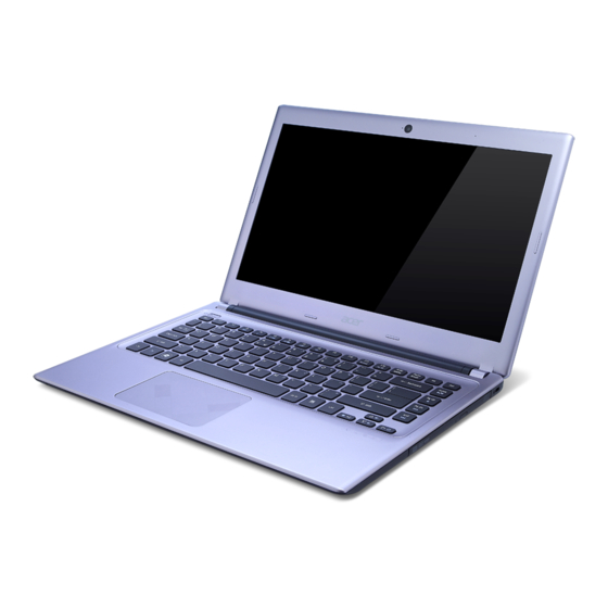
Page 21: Notebook Tour
Notebook Tour This section provides an overview of the features and functions of the notebook. Open Front View Figure 1-1. Open Front View Table 1-1. Open Front View Icon Item Description Integrated LED light Light for Webcam device Integrated webcam Web camera for video communication. -
Page 22: Close Front View
Close Front View Figure 1-2. Close Front View Table 1-2. Close Front View Icon Item Description Multi-in-1 card reader Supports MMC, MMCplus and SD cards. Note: Only one card can operate at any given time. Power indicator Indicates the computer’s power status. Blue: The computer is turned on. -
Page 23: Left View
Left View Figure 1-3. Left View Table 1-3. Left View Icon Item Description DC-in jack Connects to the AC adapter. Ventilation slots Enable the computer to stay cool, even after prolonged use. Feature port Connects to a Y cable with VGA & RJ45 port HDMI port Supports high definition digital video connections. -
Page 24: Right View
Right View Figure 1-4. Right View Table 1-4. Right View Icon Item Description Optical disc drive Internal optical disc drive; accepts CDs or DVDs. (ODD) ODD access indicator Lights up when the optical drive is active. ODD eject button Ejects the optical disc from the drive. ODD emergency Insert a paper clip to the emergency eject hole to eject hole... -
Page 25: Base View
Base View Figure 1-5. Base View Table 1-5. Base View Icon Item Description Battery pack Provides power to the computer when the power cord is unplugged. Battery release latch Releases the battery for removal. DIMM compartment Houses the computer's memory modules. Speaker Outputs sounds. -
Page 26: Touchpad Basics
Touchpad Basics Figure 1-6. Touchpad Move finger across the touchpad (1) to move the cursor. Tapping on the touchpad is the same as clicking the left button of a mouse. Press the left (2) and right (3) buttons located beneath the touchpad to perform selection and execution functions. -
Page 27: Keyboard
Keyboard The keyboard contains an overlay numeric keys, inverted “T” cursor key, Windows® key, Application key, function lock keys, and hotkeys controlling various computer features. Figure 1-7. Keyboard Lock Keys The keyboard has three lock keys which the user can toggle on and off. Figure 1-8. -
Page 28: Windows Keys
Table 1-8. Keyboard Lock Keys Lock Key Description Num Lock The key can be turned on/off via the internal keyboard (Fn+F11) or the external keyboard/keypad. Num Lock affects the external keyboard/keypad only. Shift state is NOT required for the cursor movement by the numeric ... - Page 29 Table 1-9. Windows-specific Keys Description Windows Ctrl+ +L: Lock your computer (if you are connected to a network Logo key domain), or switch users (if you're not connected to a network domain) Ctrl+ +Tab: Moves focus from Start menu, to the Quick Launch ...
- Page 30 Table 1-10. Hotkeys Hotkey Icon Function Description Fn+Home Play/Pause Play or pause a selected media file. Fn+Pg Up Stop Stop playback of the selected media file. Fn+Pg Dn Previous Return to the previous media file. Fn+End Next Jump to the next media file. Fn+...
-
Page 31: D2D Recovery
D2D Recovery The Acer Disk to Disk (D2D) recovery function allows you to use the recovery partition to troubleshoot your computer. 1. Restart the computer. 2. During POST, press F1 to access the BIOS Setup screen. 3. Press to select the Main menu. -
Page 32: System Block Diagram
System Block Diagram Figure 1-11. System Block Diagram - UMA Figure 1-12. System Block Diagram - DISCRETE 1-22 Hardware Specifications and Configurations... -
Page 33: Specification Tables
Specification Tables Computer Specifications Item Metric Imperial Dimensions Width 34.2 cm 13.46 in Depth 24.5 cm 9.64 in Height 1.99 cm 0.78 in Weight (equipped with 6-cell 1.97 kg for UMA 4.343 lb for UMA battery pack, HDD, and ODD) 2.01 kg for Discrete 4.431 lb for Discrete Input power... - Page 34 System Board Item Specification Core logic ® Mobile Intel HM70/HM77 Express Chipset ® Graphics UMA: Integrated in the Intel Core™ Mobile Processor Discrete: NVIDIA N13M-GS 1G LAN on Feature Port Realtek RTL8411 EN (thru bundled Y Cable) USB 2.0/ USB 3.0 ®...
- Page 35 Processor Specifications Item Cores/ Max Turbo Core Speed Threads Freq Tech Cache Voltage C 867 1.30 GHz 2C/2T 1.30 GHz 32 nm 2 MB 17 W 1.1 V C 877 1.40 GHz 2C/2T 1.40 GHz 32 nm 2 MB 17 W 1.1 V i3-2367M 1.4 GHz...
- Page 36 Memory Combinations Slot 1 (MB) Slot 2 (MB) Total Memory (MB) 1024 1024 2048 1024 2048 3072 1024 4096 5120 2048 1024 3072 2048 2048 4096 2048 4096 6144 4096 1024 5120 4096 2048 6144 4096 4096 8192 NOTE: The preceding table lists possible system memory configurations. Graphics Controller Item Specification...
- Page 37 System BIOS Item Specification BIOS vendor Phoenix BIOS version v1.06 BIOS ROM type Hardware BIOS ROM size 4 MB Protocols supported Legacy BIOS and EFI architectures ACPI 3.0b compliance PXE specification v2.1 SMBIOS reference specification v2.5 or later ...
- Page 38 Hard Disk Drive Item Specification Vendor and HGST HTS545032A7E384, HGST HTS545050A7E380, models SEAGATE ST320LT020/ SEAGATE 9WS142-188 9YG142-188, ST500LT012, WD WD3200LPVT-22G33T0 WD WD5000LPVT-22G33T0, Product series Hitachi Eagle/Jaguar Seagate Yarra Western Digital Scorpio Blue Configuration Interface SATA, Third Generation Capacity (GB) Bytes per sector 512, 4096, n/a,...
- Page 39 Super-Multi Drive Item Specification Vendor and models HLDS Super-Multi DRIVE 9.0mm Tray 8X GU61N LF+HF W/O bezel SATA Interface Slim-type SATA Transfer rates Read Write DVD-RAM DVD-R DVD-R DL DVD-RW DVD+R DVD+R DL DVD+RW DVD-ROM Single – Layer DVD-ROM Dual Layer –...
-
Page 40: Supported Display Resolutions
LCD Panel Item Specification Vendor and models AUO B140XW03 V0 3A LF CMI N140BGE-L42 LF / CMI BT140GW03 V2 LF LP140WH2-TLE3 LF Screen size (diagonal) 355.6 mm (14 in) Active area 309.4×173.95 mm Display resolution (pixels) HD (1366×68) Pixel pitch 0.226 mm Viewing angle (H/V) -
Page 41: Audio Codec
Audio Codec Item Specification Controller Realtek ALC271X_VB6 QFN-48 Features 98 dB Signal-to-Noise Ratio (A-weighting) for DAC output 90 dB Signal-to-Noise Ratio (A-weighting) for ADC input Internal Digital Power support: 3.3 V digital core power; 1.5–3.3 V digital IO power for HDA link; 3.0–5.0 V analog power;... -
Page 42: Lan
Item Specification LAN on Feature Port (thru Realtek RTL8411 EN bundled Y Cable) LAN connector type RJ-45 LAN connector location Left Features 10/100/1000BASE-T triple-speed MAC Compliant with IEEE standards Compliant with IEEE 802.3az draft standard for Energy Efficient Ethernet™... -
Page 43: Usb Interface
USB Interface Item Specification ® Controller USB 2.0 / USB 3.0 – Integrated in the Mobile Intel HM70/HM77 Express Chipset Number and location of USB USB 2.0 – Two (left side) port USB 3.0 – One (left side) ... -
Page 44: Battery Pack
Battery Pack Item Specification Vendor and models SANYO AL12A32 Li-Ion 4S1P Battery type Lithium-ion Pack capacity 2600 mAh Number of battery cell Package configuration 3S2P AC Adapter Item Specification Input rating 65 W Input AC current (max) 100-240 V, 1.6 A, 50-60 Hz Output 19 V, 3.42 A 1-34... -
Page 45: System Power Management
System Power Management Item Specification Power management system ACPI 3.0-compliant Power global states G3 Mechanical Off - This off state is entered through a mechanical means; no electrical current is running through the circuitry and it can be worked on without damaging the hardware or endangering service personnel. - Page 46 System Interrupt Specification (UMA) Hardware IRQ System Function IRQ0 System timer IRQ1 Standard PS/2 keyboard IRQ2 Not in use IRQ3 Not in use IRQ5 Not in use IRQ6 Not in use IRQ7 Not in use IRQ8 System CMOS/real time clock IRQ9 Broadcom xD Picture Card Host Controller IRQ10...
- Page 47 Hardware IRQ System Function IRQ 87 Microsoft ACPI-Compliant System IRQ 88 Microsoft ACPI-Compliant System IRQ 89 Microsoft ACPI-Compliant System IRQ 90 Microsoft ACPI-Compliant System IRQ 91 Microsoft ACPI-Compliant System IRQ 92 Microsoft ACPI-Compliant System IRQ 93 Microsoft ACPI-Compliant System IRQ 94 Microsoft ACPI-Compliant System IRQ 95 Microsoft ACPI-Compliant System...
- Page 48 Hardware IRQ System Function IRQ 120 Microsoft ACPI-Compliant System IRQ 121 Microsoft ACPI-Compliant System IRQ 122 Microsoft ACPI-Compliant System IRQ 123 Microsoft ACPI-Compliant System IRQ 124 Microsoft ACPI-Compliant System IRQ 125 Microsoft ACPI-Compliant System IRQ 126 Microsoft ACPI-Compliant System IRQ 127 Microsoft ACPI-Compliant System IRQ 128 Microsoft ACPI-Compliant System...
- Page 49 Hardware IRQ System Function IRQ 153 Microsoft ACPI-Compliant System IRQ 154 Microsoft ACPI-Compliant System IRQ 155 Microsoft ACPI-Compliant System IRQ 156 Microsoft ACPI-Compliant System IRQ 157 Microsoft ACPI-Compliant System IRQ 158 Microsoft ACPI-Compliant System IRQ 159 Microsoft ACPI-Compliant System IRQ 160 Microsoft ACPI-Compliant System IRQ 161 Microsoft ACPI-Compliant System...
- Page 50 Hardware IRQ System Function IRQ 186 Microsoft ACPI-Compliant System IRQ 187 Microsoft ACPI-Compliant System IRQ 188 Microsoft ACPI-Compliant System IRQ 189 Microsoft ACPI-Compliant System IRQ 190 Microsoft ACPI-Compliant System IRQ 0 System timer IRQ 18 Intel(R) 7 Series/C216 Chipset Family PCI Express Root Port 3 - 1E14 IRQ 18 Synaptics SMBus Driver...
- Page 51 System Interrupt Specification (Discrete) Hardware IRQ System Function IRQ0 System timer IRQ1 Standard PS/2 keyboard IRQ2 Not in use IRQ3 Not in use IRQ5 Not in use IRQ6 Not in use IRQ7 Not in use IRQ8 System CMOS/real time clock IRQ9 Broadcom xD Picture Card Host Controller IRQ10...
- Page 52 Hardware IRQ System Function IRQ 12 ELAN PS/2 Port Smart-Pad IRQ 22 High Definition Audio Controller IRQ 13 Numeric data processor IRQ 10 Intel(R) 7 Series/C216 Chipset Family SMBus Host Controller - 1E22 IRQ 23 Intel(R) 7 Series/C216 Chipset Family USB Enhanced Host Controller - 1E26 IRQ 4294967293 Intel(R) HD Graphics...
- Page 53 Hardware IRQ System Function IRQ 107 Microsoft ACPI-Compliant System IRQ 108 Microsoft ACPI-Compliant System IRQ 109 Microsoft ACPI-Compliant System IRQ 110 Microsoft ACPI-Compliant System IRQ 111 Microsoft ACPI-Compliant System IRQ 112 Microsoft ACPI-Compliant System IRQ 113 Microsoft ACPI-Compliant System IRQ 114 Microsoft ACPI-Compliant System IRQ 115 Microsoft ACPI-Compliant System...
- Page 54 Hardware IRQ System Function IRQ 140 Microsoft ACPI-Compliant System IRQ 141 Microsoft ACPI-Compliant System IRQ 142 Microsoft ACPI-Compliant System IRQ 143 Microsoft ACPI-Compliant System IRQ 144 Microsoft ACPI-Compliant System IRQ 145 Microsoft ACPI-Compliant System IRQ 146 Microsoft ACPI-Compliant System IRQ 147 Microsoft ACPI-Compliant System IRQ 148 Microsoft ACPI-Compliant System...
- Page 55 Hardware IRQ System Function IRQ 173 Microsoft ACPI-Compliant System IRQ 174 Microsoft ACPI-Compliant System IRQ 175 Microsoft ACPI-Compliant System IRQ 176 Microsoft ACPI-Compliant System IRQ 177 Microsoft ACPI-Compliant System IRQ 178 Microsoft ACPI-Compliant System IRQ 179 Microsoft ACPI-Compliant System IRQ 180 Microsoft ACPI-Compliant System IRQ 181 Microsoft ACPI-Compliant System...
- Page 56 System IO Address Map (UMA) I/O address (hex) System Function (shipping configuration) 3000-303F Intel(R) HD Graphics 3000 03B0-03BB Intel(R) HD Graphics 3000 03C0-03DF Intel(R) HD Graphics 3000 3088-308F Intel(R) 7 Series Chipset Family SATA AHCI Controller 309C-309F Intel(R) 7 Series Chipset Family SATA AHCI Controller 3080-3087 Intel(R) 7 Series Chipset Family SATA AHCI Controller 3098-309B...
- Page 57 I/O address (hex) System Function (shipping configuration) 00C0-00DF Direct memory access controller 0060-0060 Standard PS/2 Keyboard 0064-0064 Standard PS/2 Keyboard 0D00-FFFF PCI bus 0070-0077 System CMOS/real time clock 002E-002F Motherboard resources 004E-004F Motherboard resources 0061-0061 Motherboard resources 0063-0063 Motherboard resources 0065-0065 Motherboard resources 0067-0067...
- Page 58 System IO Address Map (Discrete) I/O address (hex) System Function (shipping configuration) 3F80-3FFF NVIDIA GeForce GT 620M 0040-0043 System timer 0050-0053 System timer 0000-001F Direct memory access controller 0000-001F PCI bus 0081-0091 Direct memory access controller 0093-009F Direct memory access controller 00C0-00DF Direct memory access controller 2000-2FFF...
- Page 59 I/O address (hex) System Function (shipping configuration) 3000-3FFF Xeon E3-1200/2nd Generation Intel(R) Core(TM) Processor Family PCI Express Root Port - 0101 EFA0-EFBF Intel(R) 7 Series/C216 Chipset Family SMBus Host Controller - 1E22 4000-403F Intel(R) HD Graphics 03B0-03BB Intel(R) HD Graphics 03C0-03DF Intel(R) HD Graphics 4098-409F...
- Page 60 1-50 Hardware Specifications and Configurations...
- Page 61 CHAPTER System Utilities...
- Page 62 BIOS Setup Utility ........2-3 Navigating the BIOS Utility .
-
Page 63: Bios Setup Utility
System Utilities BIOS Setup Utility This utility is a hardware configuration program built into a computer’s BIOS (Basic Input/Output System). The utility is pre-configured and optimized so most users do not need to run it. If configuration problems occur, the setup utility may need to be run. Refer to Chapter 4, Troubleshooting when a problem arises. -
Page 64: Bios Menus
BIOS Menus This section describes the Phoenix SecureCore Tiano BIOS Setup Utility menu tabs. NOTE: NOTE: The screenshots used in this chapter are for reference only. Actual values can vary depending on the computer model. Information This tab shows a summary of the computer‘s hardware information. Figure 2-1. - Page 65 Table 2-1. Hardware Information (Continued) Parameter Description Asset Tag Number Asset tag number of the computer Product Name Model name of the computer Manufacturer Name Computer manufacturer UUID The universally unique identifier tag assigned to the computer System Utilities...
-
Page 66: Main
Main Use this tab to set the system time and date, enable or disable boot options, and enable or disable the D2D recovery feature. Figure 2-2. BIOS Main Table 2-2. BIOS Main Parameter Description Format/Option System Time System time expressed in 24-hour format Format: HH:MM:SS (hour:minute:second) System Date... - Page 67 Table 2-2. BIOS Main (Continued) Parameter Description Format/Option Wake on Lan Option to wake up the system from a power Option: Enabled or saving mode using LAN. Disabled Wake on WLan Option to wake up the system from a power Option: Enabled or saving mode using WLAN.
-
Page 68: Security
Security Use this tab to safeguard and protect the computer from unauthorized use. Figure 2-3. BIOS Security Table 2-3. BIOS Security Parameter Description Option Supervisor Password Is Supervisor password setting or Set Clear User Password Is User password setting or Set Clear HDD Password State Hard drive password setting... -
Page 69: Setting A Password
Setting a Password Follow the succeeding instructions to set the user or supervisor passwords. 1. Press to highlight a Set _______ Password parameter and press Enter. The Set _______ Password dialog box appears. Set Supervisor Password Enter New Password Confirm New Password [ Figure 2-4. -
Page 70: Changing A Password
Changing a Password 1. Press to highlight a Set _______ Password parameter and press Enter. The Set _______ Password dialog box appears. Set Supervisor Password Enter Current Password [ Enter New Password [ Confirm New Password [ Figure 2-6. Set Supervisor Password 2. -
Page 71: Boot
Boot Use this tab to set the preferred drive sequence in which the Setup Utility attempts to boot the operating system. By default, the computer searches for boot devices in the following order: 1. Hard disk drive 2. Optical disc drive 3. -
Page 72: Exit
Exit Use the Exit tab to save or discard changes and close the BIOS Setup Utility. Figure 2-9. BIOS Exit Table 2-4. Exit Parameters Parameter Description Exit Saving Changes Close the BIOS Setup Utility and save the setup changes. Exit Discarding Changes Close the BIOS Setup Utility without saving the setup changes. -
Page 73: Bios Flash Utilities
BIOS Flash Utilities BIOS Flash memory updates are required for the following conditions: New versions of system programs New features or options Restore a BIOS when it becomes corrupted. Use the Flash utility to update the system BIOS Flash ROM. NOTE: NOTE: If a Crisis Recovery Disc is not available, create one before Flash utility is used. -
Page 74: Dos Flash Utility
DOS Flash Utility Perform the following to use the DOS Flash Utility: 1. Press F2 during boot to enter Setup Menu. 2. Select Boot Menu to modify boot priority order. Example: If using USB HDD to Update BIOS, move USB HDD to position 1. Figure 2-10. -
Page 75: Remove Hdd/Bios Password Utilities
Remove HDD/BIOS Password Utilities This section explains how to remove the HDD and BIOS passwords. Removing the HDD Password NOTE: NOTE: If the incorrect HDD password is entered three times in succession, an error is generated. (Figure 2-11) Password Error Status HDD password error code Figure 2-11. -
Page 76: Removing The Bios Passwords
4. Select option 2 (upper case ASCII code) and press Enter. 5. Write down the generated master password. 6. Reboot the computer. 7. In the HDD password prompt, type the master password generated in step 5, then press Enter. Removing the BIOS Passwords To clear a lost BIOS password (user or supervisor password), you need to short the clear password hardware gap (G2201) located on the mainboard. -
Page 77: Clearing The Bios Passwords
Clearing the BIOS Passwords 1. Shut down the computer and disconnect the AC adapter and all other peripherals from the computer. 2. Remove the battery pack and DIMM cover. 3. If the DIMM2 slot is occupied, remove the installed DIMM module and locate the G2201 gap. -
Page 78: Using Dmi Tools
Using DMI Tools The DMI (Desktop Management Interface) Tool copies BIOS information to EEPROM (Electrically Erasable Programmable Read-Only Memory). Used in the DMI pool for hardware management. LAN EEPROM Utility LAN EEPROM Utility enables to change the MAC address. Perform the following steps to use the LAN EEPROM Utility: 1. - Page 79 CHAPTER Machine Maintenance...
- Page 80 Machine Disassembly and Replacement ....3-5 Recommended Equipment ......3-5 Replacement Requirements .
- Page 81 Reinstalling the Camera Board ......3-50 Reinstalling the LCD Bezel ......3-51 Main Unit Reassembly Process .
-
Page 83: Machine Disassembly And Replacement
Machine Maintenance Machine Disassembly and Replacement This chapter contains step-by-step procedures on how to disassemble the notebook computer for maintenance and troubleshooting. Cable paths and positioning may not represent the actual model. During the removal and installation of the components, ensure all available cable channels and clips are used and that the cables are replaced in the same position. -
Page 84: Pre-Disassembly Instructions
Pre-disassembly Instructions Before proceeding with the disassembly procedure, make sure that you do the following: 1. Turn off the power to the system and all peripherals. 2. Unplug the AC adapter and all power and signal cables from the system (1). Figure 3-1. -
Page 85: Disassembly Process
For example, if you want to remove the main board, you must first remove the keyboard, then disassemble the inside assembly frame in that order. Table 3-1. Main Screw List Screw Quantity Acer Part Number M2 x L3 86.9A552.3R0 M2 x L3 (black) 86.00J40.323 M2.5 x L5... -
Page 86: External Module Disassembly Process
MODULE DIMM MODULES BRACKET Figure 3-2. External Modules Disassembly Flowchart Table 3-2. Screw List Step Screw Quantity Acer Part Number DIMM Cover Disassembly M2.5 x L5 86.00J51.535 ODD Disassembly M2.5 × L5 86.00J51.535 ODD Bracket Disassembly M2 × L3 86.9A552.3R0 Keyboard Disassembly M2.5 ×... -
Page 87: Removing The Battery Pack
Removing the Battery Pack 1. Turn the computer over so that the base is facing up. 2. Slide and hold the battery release latch to release the battery pack (1). 3. Lift the battery pack from its bay (2). Figure 3-3. Battery Pack NOTE: NOTE: The battery has been highlighted with the yellow rectangle in... -
Page 88: Removing The Dimm Cover
Removing the DIMM Cover 1. Perform the “Removing the Battery Pack” procedure described on page 3-9. 2. Remove the two screws securing the DIMM cover to the lower case assembly. Figure 3-4. DIMM Cover Screws Table 3-4. Screws Step Screw Quantity Screw Type DIMM Cover Disassembly... -
Page 89: Removing The Dimm Modules
Removing the DIMM Modules 1. Perform the “Removing the DIMM Cover” procedure described on page 3-10. 2. Push out the latches on both sides of the DIMM slot (1) until the module tilts upward, then detach the DIMM module from the slot (2). Figure 3-6. -
Page 90: Removing The Odd Module
Removing the ODD Module 1. Perform the “Removing the Battery Pack” procedure described on page 3-9. 2. Remove the screw securing the ODD module to the lower case assembly. Figure 3-7. ODD Module Screw Table 3-7. Screw Step Screw Quantity Screw Type ODD Module Disassembly M2.5 ×... - Page 91 4. Remove the two screws securing the ODD module to the bracket. Figure 3-9. ODD Bracket Screws Table 3-9. Screws Step Screw Quantity Screw Type ODD Bracket Disassembly M2 × L3 5. Detach the bracket from the module. Figure 3-10. ODD Bracket 3-13 Machine Maintenance...
- Page 92 6. Pry the ODD bezel off the module. Figure 3-11. ODD Bezel 3-14 Machine Maintenance...
-
Page 93: Removing The Keyboard
Removing the Keyboard IMPORTANT: The keyboard is easily warped or damaged during the removal process. Take care not to use excessive force when removing. 1. Perform the “Removing the Battery Pack” procedure described on page 3-9. 2. Perform the “Removing the ODD Module”... - Page 94 5. Use a non-marring plastic flat-blade screwdriver to push the latches on the top side of the keyboard. Figure 3-13. Keyboard Latches 6. Gently lift the keyboard out of its socket and slide it toward the LCD panel (1). Release the connector latch (2), disconnect the cable from the mainboard (3), then detach the keyboard from the computer.
-
Page 95: Main Unit Disassembly Process
MODULE MODULE MODULE Figure 3-15. Main Unit Disassembly Flowchart Table 3-15. Screw List Step Screw Quantity Acer Part Number Palmrest Module/Upper Case Disassembly M2.5 × L5 86.00J51.535 Upper Case Disassembly M2.5 × L5 86.00J51.535 Touchpad Board Disassembly M2 × L3 86.9A552.3R0... -
Page 96: Removing The Palmrest Module/Upper Case
Removing the Palmrest Module/Upper Case 1. Perform the “External Module Disassembly Process” procedures described on pages to 3-15. 2. Remove the seventeen base side screws securing the upper case to the lower case. Figure 3-16. Upper Case Screws – Base Side Table 3-16. - Page 97 4. Release the connector latches from the mainboard (1), then disconnect the power button and touchpad cables (2). Figure 3-17. Power Button and Touchpad Cables 5. Remove the three screws securing the upper case to the lower case assembly. Figure 3-18. Upper Case Screws – Top Side Table 3-18.
- Page 98 6. Gently lift the upper case from the lower case. Figure 3-19. Upper Case 3-20 Machine Maintenance...
-
Page 99: Removing The Touchpad Board
Removing the Touchpad Board 1. Perform the “Removing the Palmrest Module/Upper Case” procedure described on page 3-18. 2. Release the connector latch from the touchpad board (1), then disconnect the touchpad cable (2). Figure 3-20. Touchpad Cable 3. Release the touchpad cable from the adhesive tape securing it (1), then detach the touchpad cable from the touchpad board (2). - Page 100 4. Remove the three screws securing the touchpad board to the upper case assembly. Figure 3-22. Touchpad Screws Table 3-22. Screws Step Screw Quantity Screw Type Touchpad Module Disassembly M2 × L3 5. Detach the touchpad board from the upper case assembly. Figure 3-23.
-
Page 101: Removing The Power Button Board
Removing the Power Button Board 1. Perform the “Removing the Palmrest Module/Upper Case” procedure described on page 3-18. 2. Release the connector latch from the power button board (1), then disconnect the power button cable (2). Figure 3-24. Power Button Cable 3. - Page 102 5. Detach the power button board and cable from the upper case. Figure 3-26. Power Button Board NOTE: NOTE: A circuit board that is > 10cm has been highlighted with a yellow rectangle in Figure 3-26. Follow the local regulations for disposing this type of circuit board. 3-24 Machine Maintenance...
-
Page 103: Removing The Hdd Module
Removing the HDD Module 1. Perform the “Removing the Palmrest Module/Upper Case” procedure described on page 3-18. 2. Gently lift the HDD assembly from its socket. Figure 3-27. HDD Module 3. Disconnect the HDD cable from the HDD module. Figure 3-28. HDD Cable 3-25 Machine Maintenance... -
Page 104: Removing The Wlan Module
Removing the WLAN Module 1. Perform the “Removing the Palmrest Module/Upper Case” procedure described on page 3-18. 2. Unplug the two (2) antenna cables from the WLAN module. Figure 3-29. WLAN Module Antennas IMPORTANT: For reference during machine reassembly, note which cable color corresponds to the main (black) and auxiliary (white) connectors. - Page 105 4. Detach the WLAN module from the slot. Figure 3-31. WLAN Module NOTE: NOTE: A circuit board that is > 10cm has been highlighted with a yellow rectangle in Figure 3-31. Follow the local regulations for disposing this type of circuit board. 3-27 Machine Maintenance...
-
Page 106: Removing The Mainboard
Removing the Mainboard 1. Perform the “Removing the Palmrest Module/Upper Case” procedure described on page 3-18. 2. Perform the “Removing the ODD Module” procedure described on page 3-12. 3. Perform the “Removing the HDD Module” procedure described on page 3-25. 4. - Page 107 9. Remove the screw securing the mainboard to the lower case assembly. Figure 3-34. Mainboard Screw Table 3-34. Screw Step Screw Quantity Screw Type Mainboard Disassembly M2 × L3 NOTE: NOTE: A circuit board that is > 10cm has been highlighted with a yellow rectangle in Figure 3-34.
- Page 108 11. Disconnect the HDD cable from the mainboard (1). 12. Disconnect the battery cable from the mainboard (2). 13. Disconnect the DC-In cable from the mainboard (3), then lift the mainboard out of the lower case. Figure 3-36. HDD, Battery and DC-In Cables 3-30 Machine Maintenance...
-
Page 109: Removing The Thermal Module
Removing the Thermal Module 1. Perform the “Removing the Mainboard” procedure described on the preceding on page 3-28. 2. Disconnect the thermal module fan cable from the mainboard. Figure 3-37. Fan Cable 3. Loosen the spring-loaded captive screws securing the thermal module. Follow the screw sequence indicated on Figure 3-38. - Page 110 4. Gently lift and detach the thermal module from the mainboard. Figure 3-39. Thermal Module 3-32 Machine Maintenance...
-
Page 111: Removing The Dc In Module
Removing the DC In Module 1. Perform the “Removing the Mainboard” procedure described on page 3-28. 2. Detach the DC In module from the lower case assembly. Figure 3-40. DC In Cable 3-33 Machine Maintenance... -
Page 112: Removing The Battery Connector
Removing the Battery Connector 1. Perform the “Removing the Mainboard” procedure described on the preceding on page 3-28. 2. Remove the two screws securing the battery connector to the lower case assembly. Figure 3-41. Battery Connector Screws Table 3-41. Screws Step Screw Quantity... -
Page 113: Removing The Speaker Module
Removing the Speaker Module 1. Perform the “Removing the Mainboard” procedure described on page 3-28. 2. Detach the speaker cables from lower case assembly. Figure 3-43. Speaker Cable 3. Remove the four screws securing the Speaker Module to the lower case assembly. Figure 3-44. - Page 114 4. Gently lift the Speaker Module and detach it from the lower case assembly. Figure 3-45. Speakers 3-36 Machine Maintenance...
-
Page 115: Removing The Lcd Module
Removing the LCD Module 1. Perform the “Removing the Mainboard” procedure described on page 3-28. 2. Gently pull out the WLAN antenna cables from lower case; remove the adhesive tapes securing the cables and release the cables from the latches. Figure 3-46. - Page 116 4. Detach the LCD module from the lower case. Figure 3-48. LCD Module 3-38 Machine Maintenance...
-
Page 117: Lcd Module Disassembly Process
BACK PANEL LCD FPC CABLE MICROPHONE BRACKETS Figure 3-49. LCD Module Disassembly Flowchart Table 3-49. Screw List Step Screw Quantity Acer Part Number LCD Panel Disassembly M2 x L3 86.00J40.323 LCD Bracket Disassembly M2 x L3 86.00J40.323 3-39 Machine Maintenance... -
Page 118: Removing The Lcd Bezel
Removing the LCD Bezel 1. Perform the “Removing the LCD Module” procedure described on page 3-37. 2. Gently pry loose the LCD bezel from the LCD cover (1). Start on the bottom side, continue to the left and right sides, and finally the top side. Detach the bezel from the LCD assembly (2). -
Page 119: Removing The Camera Board
Removing the Camera Board 1. Perform the “Removing the LCD Bezel” procedure described on page 3-40. 2. Disconnect the camera cable from the camera board. Figure 3-51. Camera Cable 3. Gently pry the camera board off the LCD back cover. Figure 3-52. -
Page 120: Removing The Lcd Panel
Removing the LCD Panel 1. Perform the “Removing the LCD Bezel” procedure described on page 3-40. 2. Remove the four screws securing the LCD panel to the LCD back cover. Figure 3-53. LCD Panel Screws Table 3-53. Screws Step Screw Quantity Screw Type LCD Panel Disassembly... -
Page 121: Removing The Lcd Fpc Cable
Removing the LCD FPC Cable 1. Perform the “Removing the LCD Panel” procedure described on page 3-42. 2. Detach the self adhesive tapes securing the FPC cable to the back of the LCD Panel. Figure 3-55. FPC Cable Adhesive Tapes 3. -
Page 122: Removing The Lcd Brackets
Removing the LCD Brackets 1. Perform the “Removing the LCD Panel” procedure described on page 3-42. 2. Remove the six screws securing the left and right LCD brackets to the LCD back cover. Figure 3-57. LCD Bracket Screws Table 3-57. Screws Step Screw Quantity... -
Page 123: Removing The Microphone
Removing the Microphone 1. Perform the “Removing the LCD Panel” procedure described on page 3-42. 2. Release the microphone cable from the adhesive tapes securing them. Figure 3-59. Microphone Adhesive Tapes 3. Gently pry the microphone off the LCD back panel. Figure 3-60. -
Page 124: Lcd Module Reassembly Process
LCD Module Reassembly Process Reinstalling the Microphone 1. Gently place the microphone on its socket in the LCD back panel. Figure 3-61. Microphone 2. Secure the microphone cable to the LCD back panel using adhesive tapes. Figure 3-62. Microphone Adhesive Tapes 3-46 Machine Maintenance... -
Page 125: Reinstalling The Lcd Brackets
Reinstalling the LCD Brackets 1. Place the LCD bracket into the LCD back cover. Figure 3-63. LCD Bracket 2. Secure the left and right LCD brackets to the LCD back cover using six screws. Figure 3-64. LCD Bracket Screws Table 3-64. Screws Step Screw Quantity... -
Page 126: Reinstalling The Lcd Fpc Cable
Reinstalling the LCD FPC Cable 1. Connect the FPC cable to the LCD panel (1), then secure the FPC cable to the LCD panel using transparent adhesive tape (2). Figure 3-65. FPC Cable 2. Secure the FPC cable to the back of the LCD Panel using self-adhesive tape. Figure 3-66. -
Page 127: Reinstalling The Lcd Panel
Reinstalling the LCD Panel 1. Gently place the LCD panel into the LCD back cover (1), then insert the LCD cable into the latch located near the hinge (2). Figure 3-67. LCD Cable 2. Secure the LCD panel to the LCD back cover using four screws. Figure 3-68. -
Page 128: Reinstalling The Camera Board
Reinstalling the Camera Board 1. Gently place the camera board into the LCD back cover. Figure 3-69. Camera Board 2. Connect the camera cable to the camera board. Figure 3-70. Camera Cable 3-50 Machine Maintenance... -
Page 129: Reinstalling The Lcd Bezel
Reinstalling the LCD Bezel 1. Place the bezel into the LCD assembly then gently press all sides until the bezel latch into place. Figure 3-71. LCD Bezel 3-51 Machine Maintenance... -
Page 130: Main Unit Reassembly Process
Main Unit Reassembly Process Reinstalling the LCD Module 1. Place the LCD module into its socket in the lower case. Figure 3-72. LCD Module 2. Secure the LCD module to the lower case using two screws. Figure 3-73. LCD Module Hinge Screws Table 3-73. - Page 131 3. Insert the cables in the lower case latches as shown, then secure them to the lower case using adhesive tapes. Figure 3-74. WLAN Antenna Cables - Latches and Adhesive Tapes 3-53 Machine Maintenance...
-
Page 132: Reinstalling The Speaker Module
Reinstalling the Speaker Module 1. Perform the “Removing the Mainboard” procedure described on page 3-28. 2. Place the Speaker Module into the lower case assembly. Figure 3-75. Speakers 3. Secure the Speaker Module to the lower case assembly using four screws. Figure 3-76. - Page 133 4. Insert the cables in the lower case latches as shown, then secure them to the lower case using adhesive tapes Figure 3-77. Speaker Cable 3-55 Machine Maintenance...
-
Page 134: Reinstalling The Battery Connector
Reinstalling the Battery Connector 1. Place the battery connector into the lower case assembly. Figure 3-78. Battery Connector 2. Secure the battery connector to the lower case assembly using two screws. Figure 3-79. Battery Connector Screws Table 3-79. Screws Step Screw Quantity Screw Type... -
Page 135: Reinstalling The Dc In Module
Reinstalling the DC In Module 1. Place the DC In module into the lower case assembly. Figure 3-80. DC In Cable 3-57 Machine Maintenance... -
Page 136: Reinstalling The Thermal Module
Reinstalling the Thermal Module 1. Place the thermal module into the mainboard. Figure 3-81. Thermal Module 2. Tighten the spring-loaded captive screws securing the thermal module. Follow the screw sequence indicated on Figure 3-82. Figure 3-82. Thermal Module Screws Table 3-82. Screws Step Screw Quantity... - Page 137 3. Connect the thermal module fan cable to the mainboard. Figure 3-83. Fan Cable 3-59 Machine Maintenance...
-
Page 138: Reinstalling The Mainboard
Reinstalling the Mainboard 1. Place the mainboard into the lower case, then connect the HDD cable to the mainboard (1). 2. Connect the battery cable to the mainboard (2), then connect the DC-In cable to the mainboard (3). Figure 3-84. HDD, Battery and DC-In Cables 3. - Page 139 4. Secure the mainboard to the lower case assembly using one screw. Figure 3-86. Mainboard Screw Table 3-86. Screw Step Screw Quantity Screw Type Mainboard Reassembly M2 × L3 5. Connect the cable to the mainboard (1), then secure the LCD cable to the mainboard using adhesive tape (2).
- Page 140 7. Connect the speaker cable to the main board. Figure 3-88. Speaker Cable 3-62 Machine Maintenance...
-
Page 141: Reinstalling The Wlan Module
Reinstalling the WLAN Module 1. Insert the WLAN module into its slot in the mainboard. Figure 3-89. WLAN Module 2. Secure the WLAN module to the mainboard using one screw. Figure 3-90. WLAN Module Screw Table 3-90. Screw Step Screw Quantity Screw Type WLAN Module Reassembly... - Page 142 3. Plug the two (2) antenna cables to the WLAN module. Figure 3-91. WLAN Module Antennas IMPORTANT: Refer to your machine disassembly note to determine which cable color corresponds to the main (black) and auxiliary (white) connectors. 3-64 Machine Maintenance...
-
Page 143: Reinstalling The Hdd Module
Reinstalling the HDD Module 1. Connect the HDD cable to the HDD module. Figure 3-92. HDD Cable 2. Gently insert the HDD assembly into its socket. Figure 3-93. HDD Module 3-65 Machine Maintenance... -
Page 144: Reinstalling The Power Button Board
Reinstalling the Power Button Board 1. Place the power button board and cable into the upper case. Figure 3-94. Power Button Board 2. Secure the power button board to the upper case using one screw. Figure 3-95. Power Button Board Screw Table 3-95. - Page 145 3. Turn the upper case over. 4. Connect the power button cable to the power button board (1), then press the connector latch (2) until it locks into place. Figure 3-96. Power Button Cable 3-67 Machine Maintenance...
-
Page 146: Reinstalling The Touchpad Board
Reinstalling the Touchpad Board 1. Place the touchpad board into the upper case assembly. Figure 3-97. Touchpad Board 2. Connect the touchpad cable to the touchpad board (1), then press the connector latch (2) until it locks into place. Figure 3-98. Touchpad Cable 3. - Page 147 Figure 3-99. Touchpad Adhesive Tape 4. Secure the touchpad board to the upper case assembly using three screws. Figure 3-100. Touchpad Screws Table 3-100. Screws Step Screw Quantity Screw Type Touchpad Module Reassembly M2 × L3 3-69 Machine Maintenance...
-
Page 148: Reinstalling The Palmrest Module/Upper Case
Reinstalling the Palmrest Module/Upper Case 1. Place the upper case into the lower case assembly. Figure 3-101. Upper Case 2. Secure the upper case to the lower case assembly using three screws. Figure 3-102. Upper Case Screws – Top Side Table 3-102. - Page 149 3. Connect the power button and touchpad cables to the mainboard (1), then press the connector latches (2) until they lock into place. Figure 3-103. Power Button and Touchpad Cables 4. Turn the computer over to acces the base side of the lower case assembly. 5.
-
Page 150: External Module Reassembly Process
External Module Reassembly Process Reinstalling the Keyboard 1. Turn the computer over and open the LCD panel. 2. Connect the cable to the mainboard (1), then press the connector latch (2) until it locks into place. Place the keyboard into its socket (3). Figure 3-105. - Page 151 5. Secure the keyboard to the lower case assembly using one screw. Figure 3-107. Upper Case Screws – Base Side Table 3-107. Screws Step Screw Quantity Screw Type Keyboard Reassembly M2.5 × L5 3-73 Machine Maintenance...
-
Page 152: Reinstalling The Odd Module
Reinstalling the ODD Module 1. Press the ODD bezel into the module until it latch into place. Figure 3-108. ODD Bezel 2. Place the bracket into the module. Figure 3-109. ODD Bracket 3-74 Machine Maintenance... - Page 153 3. Secure the ODD module to the bracket using two screws. Figure 3-110. ODD Bracket Screws Table 3-110. Screws Step Screw Quantity Screw Type ODD Bracket Reassembly M2 × L3 4. Gently push the ODD module into the ODD drive bay until the ODD connector latch into place.
- Page 154 5. Secure the ODD module to the lower case assembly using one screw. Figure 3-112. ODD Module Screw Table 3-112. Screw Step Screw Quantity Screw Type ODD Module Reassembly M2.5 × L5 3-76 Machine Maintenance...
-
Page 155: Reinstalling The Dimm Modules
Reinstalling the DIMM Modules 1. Insert the DIMM module into the slot (1), then push the it downward until it latches into place (2). Figure 3-113. DIMM Modules 2. Repeat Step 1 to reinstall the remaining DIMM module. 3-77 Machine Maintenance... -
Page 156: Reinstalling The Dimm Cover
Reinstalling the DIMM Cover 1. Place the DIMM cover into the computer and press it downward until the DIMM cover latches into place. Figure 3-114. DIMM Cover 2. Secure the DIMM cover to the lower case assembly using two screws. Figure 3-115. -
Page 157: Reinstalling The Battery Pack
Reinstalling the Battery Pack 1. Insert the battery pack into its bay until it latches into place. Figure 3-116. Battery Pack 3-79 Machine Maintenance... - Page 158 3-80 Machine Maintenance...
- Page 159 CHAPTER Troubleshooting...
- Page 160 Introduction ......... . 4-3 General Information .
-
Page 161: Introduction
NOTE: NOTE: The diagnostic tests are intended for Acer products only. Non-Acer products, prototype cards, or modified options can give false errors and invalid system responses. 1. Obtain as much detailed information as possible about the problem. -
Page 162: Power On Issues
Power On Issues If the system does not power on, perform the following, one at a time, to correct the problem. Do not replace a non-defective FRU. Figure 4-1. Power On Issue Computer Shuts Down Intermittently If the system powers off at intervals, perform the following. 1. -
Page 163: No Display Issues
No Display Issues If the Display does not work, perform the following, one at a time. Do not replace a non-defective FRU: Figure 4-2. No Display Issue No POST or Video If the POST or video does not appear, perform the following one at a time. 1. -
Page 164: Abnormal Video
3. Drain stored power by removing the power cable and the battery pack. Hold the power button for 10 seconds. 4. Connect the power cable and reboot the computer. 5. Connect an external monitor to the computer and switch between the internal display and the external display by pressing Fn+F5. -
Page 165: Lcd Failure
7. If the issue is still not resolved, refer to the Online Support Information on page 8. Run the Windows Memory Diagnostic from the operating system DVD and follow the on-screen prompts. 9. If the issue is still not resolved, refer to the Online Support Information on page LCD Failure... -
Page 166: Keyboard Failure
Keyboard Failure If the Keyboard fails, perform the following, one at a time. Do not replace a non-defective FRU: Figure 4-4. Keyboard Failure Troubleshooting... -
Page 167: Touchpad Failure
Touchpad Failure If the Touchpad fails, perform the following, one at a time. Do not replace a non-defective FRU: Figure 4-5. Touchpad Failure Troubleshooting... -
Page 168: Internal Speaker Failure
Internal Speaker Failure If internal Speakers fail, perform the following, one at a time. Do not replace a non-defective FRU: Figure 4-6. Internal Speaker Failure Sound Problems Perform the following, one at a time. 1. Boot the computer. 2. Navigate to Start Control Panel System and Maintenance System Device Manager. - Page 169 Drag the slider to 50. Confirm that the volume is not muted. Click Mixer to verify that other audio applications are set to 50 and not muted. 6. Navigate to Start Control Panel Hardware and Sound Sound. Confirm that Speakers are selected as the default audio device (green check mark).
-
Page 170: Microphone Failure
Microphone Failure If internal or external Microphones fail, perform the following, one at a time. Figure 4-7. Microphone Failure 1. Check that the microphone is enabled. Navigate to Start Control Panel Hardware and Sound Sound and select the Recording tab. 2. -
Page 171: Usb Failure
USB Failure If the USB fails, perform the following, one at a time. Do not replace a non-defective FRU: Figure 4-8. USB Failure 4-13 Troubleshooting... -
Page 172: Wlan Failure
WLAN Failure If the WLAN fails, perform the following, one at a time. Do not replace a non-defective FRU: Figure 4-9. WLAN Failure 4-14 Troubleshooting... -
Page 173: Bluetooth Failure
Bluetooth Failure If the Bluetooth fails, perform the following, one at a time. Do not replace a non-defective FRU: Figure 4-10. Bluetooth Failure 4-15 Troubleshooting... -
Page 174: Card Reader Failure
Card Reader Failure If the Card Reader fails, perform the following, one at a time. Do not replace a non-defective FRU: Figure 4-11. Card Reader Failure 4-16 Troubleshooting... -
Page 175: Thermal Unit Failure
Thermal Unit Failure If the Thermal Unit fails, perform the following, one at a time. Do not replace a non-defective FRU: Figure 4-12. Thermal Unit Failure 4-17 Troubleshooting... -
Page 176: Other Functions Failure
Other Functions Failure 1. Check if drives are functioning correctly. 2. Check if external modules are functioning correctly. 3. Change mainboard to check if current one is defective. 4-18 Troubleshooting... -
Page 177: Intermittent Problems
1. Remove power from the computer. 2. Visually check the components for damage. If any problems are found, replace the FRU. 3. Remove or disconnect all of the following devices: Non-Acer devices Printer, mouse, and other external devices ... -
Page 178: Error Codes
Error Codes Table 4-2. Error Codes Error Codes Error Messages Equipment Configuration Error Causes: 1. CPU BIOS Update Code Mismatch 2. IDE Primary Channel Master Drive Error (The causes will be shown before “Equipment Configuration Error”) Memory Error at xxxx:xxxx:xxxxh (R:xxxxh, W:xxxxh) Real Time Clock Error CMOS Battery Bad CMOS Checksum Error... -
Page 179: Bios Beep Codes
BIOS Beep Codes Table 4-3. BIOS Beep Codes Code Beeps POST Routine Description Verify Real Mode Disable Non-Maskable Interrupt (NMI) Get CPU type Initialize system hardware Initialize chipset with initial POST values Set IN POST flag Initialize CPU registers Enable CPU cache Initialize caches to initial POST values Initialize I/O component Initialize the local bus IDE... - Page 180 Table 4-3. BIOS Beep Codes Code Beeps POST Routine Description Enable cache before system BIOS shadow 1-4-1-1 RAM failure on data bits xxxx of high byte of memory bus Test CPU bus-clock frequency Initialize Phoenix Dispatch Manager Warm start shut down Shadow system BIOS ROM Autosize cache Advanced configuration of chipset registers...
- Page 181 Table 4-3. BIOS Beep Codes Code Beeps POST Routine Description Setup System Management Mode (SMM) area Display external L2 cache size Load custom defaults (optional) Display shadow-area message Display possible high address for UMB recovery Display error messages Check for configuration errors Check for keyboard errors Set up hardware interrupt vectors Initialize coprocessor if present...
- Page 182 Table 4-3. BIOS Beep Codes Code Beeps POST Routine Description Check for SMART drive (optional) Shadow option ROMs Set up Power Management Initialize security engine (optional) Enable hardware interrupts Determine number of ATA and SCSI drives Set time of day Check key lock Initialize Typematic rate Erase F2 prompt...
- Page 183 Table 4-3. BIOS Beep Codes Code Beeps POST Routine Description Force check (optional) Extended checksum (optional) Unknown interrupt Initialize the chipset Initialize the bridge Initialize the CPU Initialize the system timer Initialize system I/O Check force recovery boot Checksum BIOS ROM Go to BIOS Set Huge Segment Initialize Multi Processor...
-
Page 184: Post Codes
POST Codes There are two types of POST codes: Progress Codes and Error Codes. Progress Codes are designed to show the execution point while booting or executing services. Error Codes are designed to halt on exceptional (fatal) error conditions. Component Codes The Component Code is an unsigned integer value that is assigned by the build process. - Page 185 Table 4-4. Component Codes Range Description 0x20-0x9f These values are reserved for SecureCore Tiano™ core components. POSTCODE_CC_VARIABLE_SERVICES (0x20) POSTCODE_CC_KEYBOARD_CONTROLLER (0x21) POSTCODE_CC_BOOT_MODE (0x22) POSTCODE_CC_S3_SUPPORT (0x23) POSTCODE_CC_TCG (0x24) POSTCODE_CC_HDD_PASSWORD (0x25) POSTCODE_CC_CPU_IO (0x26) POSTCODE_CC_BOOT_SCRIPT (0x27) POSTCODE_CC_STATUS_CODE (0x28) POSTCODE_CC_DATA_HUB (0x29) POSTCODE_CC_HII_DATABASE (0x2a) POSTCODE_CC_RESET (0x2b) POSTCODE_CC_METRONOME (0x2c) POSTCODE_CC_INTERRUPT_CONTROLLER (0x2d) POSTCODE_CC_DIAGNOSTIC_SUMMARY (0x2e)
- Page 186 Table 4-4. Component Codes Range Description POSTCODE_CC_HII_FORMS_BROWSER (0x3a) POSTCODE_CC_BOOT_MENU (0x3b) POSTCODE_CC_USER_MANAGER (0x3c) POSTCODE_CC_TIMER (0x3d) POSTCODE_CC_PCI_BUS (0x3e) POSTCODE_CC_ISA_BUS (0x3f) POSTCODE_CC_IDE_BUS (0x40) POSTCODE_CC_AHCI_BUS (0x41) POSTCODE_CC_SCSI_BUS (0x42) POSTCODE_CC_USB_BUS (0x43) POSTCODE_CC_FLOPPY (0x44) POSTCODE_CC_SERIAL_PORT (0x45) POSTCODE_CC_PS2_MOUSE (0x46) POSTCODE_CC_PS2_KEYBOARD (0x47) POSTCODE_CC_EHCI (0x48) POSTCODE_CC_XHCI (0x49) POSTCODE_CC_UHCI (0x4a) POSTCODE_CC_OHCI (0x4b) POSTCODE_CC_USB_KEYBOARD (0x4c) POSTCODE_CC_USB_MOUSE (0x4d)
- Page 187 Table 4-4. Component Codes Range Description 0xa0-0xaf These values are reserved for SecureCore Tiano™ platform components. POSTCODE_CC_PLATFORM_STAGE0 (0xa0) - Early PEI Platform Initialization. POSTCODE_CC_PLATFORM_STAGE1 (0xa1) -PEI Platform Initialization. POSTCODE_CC_PLATFORM_DXE (0xa1) - DXE Platform Initialization. POSTCODE_CC_PLATFORM_SMM (0xa1) - SMM Platform Initialization. POSTCODE_CC_PLATFORM_FLASH (0xa2) - Flash Platform Initialization.
- Page 188 Table 4-4. Component Codes Range Description 0xe0-0xff These are not components, but rather represent Architectural Progress Codes or Error Codes detailing milestones in the system boot progress. The corresponding Progress Code value is always set to zero. POSTCODE_PC_SEC_ENTRY (0xe0) - Reset vector. POSTCODE_PC_SEC_EXIT (0xe1) - Leaving SEC/Going to PEI.
-
Page 189: Progress Codes
Progress Codes This section describes the progress code values. Table 4-5. Progress Codes Range Description 0x00-0x1f Standard progress Codes. All other values are reserved. POSTCODE_PC_COMP_PEI_BEGIN (0x01) - The component was loaded and the PEI entry point called. POSTCODE_PC_COMP_PEI_END (0x02) - The component returned from the PEI entry point. - Page 190 4-32 Troubleshooting...
- Page 191 CHAPTER Jumper and Connector Locations...
-
Page 192: Mainboard Layout
Mainboard Layout ........5-3 Clearing Password Check and BIOS Recovery ... . .5-7 Clearing the BIOS Passwords . -
Page 193: Jumper And Connector Locations
Jumper and Connector Locations Mainboard Layout Figure 5-1. Mainboard Top View (UMA) Table 5-1. Mainboard Top View (UMA) Code Component Code Component PWRCN1 Power button board cable LCD1 LCD cable connector connector WLAN1 Mini card slot (for wireless Backlight keyboard module) cable connector TPAD1... - Page 194 Figure 5-2. Mainboard Top View (Discreet) Table 5-2. Mainboard Top View (Discreet) Code Component Code Component LCD1 LCD cable connector PWRCN1 Power button board cable connector Backlight keyboard cable WLAN1 Mini card slot (for connector wireless module) Keyboard cable connector TPAD1 Touchpad cable connector (15”...
- Page 195 Figure 5-3. Mainboard Bottom View (UMA) Table 5-3. Mainboard Bottom View (UMA) Code Component Code Component LCD1 LCD cable connector AUSB3 USB 2.0 port Backlight keyboard cable LOUT1 Headphones/ speaker/ connector line-out jack port CPU1 DIMM slot 2 WLAN1 Mini card slot (for wireless DIMM slot 1 module) Feature port...
- Page 196 Figure 5-4. Mainboard Bottom View (Discrete) Table 5-4. Mainboard Bottom View (Discrete) Code Component Code Component DCIN1 DC-In cable connector DIMM slot 2 CPU1 DIMM slot 1 Feature port SPK1 Speaker cable connector HDMI1 HDMI port RTC1 RTC battery AUSB1 USB 3.0 port HDD2 HDD cable connector...
-
Page 197: Clearing Password Check And Bios Recovery
Clearing Password Check and BIOS Recovery This section provides procedures for: Clearing the BIOS passwords Performing a BIOS recovery Clearing the BIOS Passwords To clear a lost BIOS password (user or supervisor password), you need to short the clear password hardware gap (G2201) located on the mainboard. -
Page 198: Performing A Bios Recovery
Performing a BIOS Recovery Boot Block An interruption during a BIOS flash procedure (e.g. a power outage) can corrupt the BIOS code, which will cause the system to go into an unbootable state. The BIOS boot block refers to a special BIOS program that can be used to boot up a system with minimum BIOS initialization.You need to access and execute the boot block to reboot the computer and recover the regular BIOS code. -
Page 199: Performing A Bios Recovery
Performing a BIOS recovery NOTE: NOTE: Make sure the battery pack is installed to the system and that the computer is connected to a UPS unit during the BIOS recovery process. The function hotkey sequence Fn+Esc is used to enable the BIOS recovery process when system is powered On during BIOS POST. - Page 200 5-10 Jumper and Connector Locations...
- Page 201 CHAPTER FRU List...
-
Page 202: Aspire Ms2360
Aspire MS2360 Exploded Diagrams........6-4 Main Assembly . - Page 203 DIFFERENT part number code from those given in the FRU list of this printed Service Guide. Users MUST use the local FRU list provided by the regional Acer office to order FRU parts for repair and service of customer machines.
-
Page 204: Aspire Ms2360
Aspire MS2360 Exploded Diagrams Main Assembly Figure 6-1. Main Assembly Exploded Diagram Table 6-1. Main Assembly Exploded Diagram Description Part Number Panel assembly 60.4TU13.011 CCD module LCD module Husk hinge (left) 34.4TU15.001 Husk hinge (right) 34.4TU14.001 LCD bezel assembly 60.4TU14.001 FRU (Field Replaceable Unit) List... - Page 205 Table 6-1. Main Assembly Exploded Diagram Description Part Number LVDS combo cable 50.4TU08.001 Antenna WIFI main (left) 25.90ADQ.001 Antenna WIFI aux. (right) 25.90ADR.001 Keyboard 60.4TU09.002 Power board Power board EMI shield / mylar 40.4TU18.001 Touch pad bracket assembly 60.4TU07.002 Touch pad module 60.4TU15.002 Upper case assembly 65.4TU12.001...
-
Page 206: Lcd Assembly
LCD Assembly Figure 6-2. LCD Assembly Exploded Diagram Table 6-2. LCD Assembly Exploded Diagram Description Part Number LCD bezel assembly 60.4TU37.001 LCD module Hinge (left) 34.4TU15.001 Hinge (right) 34.4TU14.001 CCD module Antenna WIFI (left) 25.90ADQ.001 Antenna WIFI (right) 25.90ADR.001 LVDS combo cable 50.4TU08.001 Panel painting 60.4TU13.001... -
Page 207: Fru List
FRU List Category Description Acer Part No. ADAPTER ADP 65W 19V LV5 AP.06501.033 ADP-65VH BA LOW PROFILE ADP 65W 19V YELLOW AP.06503.031 LITE-ON PA-1650-86AW BATTERY BTY PACK LI+ SANYO 4C KT.00403.003 2.6AH SANYO BOARDS HUSK POWER BD 11957-1 55.M2DN1.001 MP D TOUCHPAD EMC 56.M1BN1.002... - Page 208 Category Description Acer Part No. CABLES C.A. FFC PB HUSK CVILUX 50.M2DN1.001 C.A. FFC PB HUSK HB 50.M2DN1.001 C.A. FFC TP HUSK CVILUX RESERVE C.A. FFC TP HUSK HB RESERVE C.A. HUSK BATTERY CABLE 50.M1DN1.001 C.A. HUSK BATTERY CABLE 50.M1DN1.001 WANSHIH C.A.
- Page 209 Category Description Acer Part No. C.A_HUSK_LVDS_HL 50.M1DN1.002 C.A_LVDS_HUSK YY 50.M1DN1.002 C.A_LVDS_HUSK_ICT 50.M1DN1.002 C.A_LVDS_HUSK_UMA_HL 50.M1BN1.001 C.A_LVDS_HUSK_UMA_ICT 50.M1BN1.001 C.A_LVDS_HUSK_UMA_WA 50.M1BN1.001 NSHIH C.A_LVDS_HUSK_UMA_YY 50.M1BN1.001 C.A_LVDS_HUSK_WANSHI 50.M1DN1.002 ARGENTINA 1M 27.RSF01.012 AUSTRALIA BK 1M HAVE 27.RSF01.016 LABEL BRAZIL BK 1M 27.RSF01.013 CHINA BK 1M 27.RSF01.007 DENMARK BK 1M 27.RSF01.004...
- Page 210 Category Description Acer Part No. CABLES UK BK 1M 27.RSF01.003 US BK 1M 27.RSF01.001 US POWER CORD 1M 27.RSF01.001 CAMERA CAMERA 1.0M_HD 57.M2DN1.001 11P2SF167 LITEON CAMERA 1.0M_HD 57.M2DN1.002 CNFB1D921004970LH CHICONY CAMERA 1.0M_HD 57.M2DN1.003 HF1016-A21U-OV02 SUYIN CASE/COVER/BRACKET ASSEMBLY 60 HUSK LCASE ASSY 60.M1BN1.001...
- Page 211 Category Description Acer Part No. ASSY_60_PANEL_BLUE__P 60.M1BN1.006 AINTING_HUSK ASSY_60_PANEL_HUSK_M 60.M1BN1.005 BLUE ASSY_60_PANEL_HUSK_M 60.M3BN1.003 SILVER ASSY_60_PANEL_HUSK_M 60.M1CN1.003 _P PURPLE ASSY_60_PANEL_PURPLE_ 60.M1CN1.004 _PAINTING_HUSK ASSY_60_PANEL_SILVER__ 60.M3BN1.004 PAINTING_HUSK ASSY_HUSK_TP_MODULE RESERVE DUMMY CARD HUSK 42.M2DN1.002 HINGE_L_HUSK_LH 33.M1BN1.001 HINGE_L_HUSK_SNR 33.M1BN1.001 HINGE_L_HUSK_SZS 33.M1BN1.001 HINGE_R_HUSK_LH 33.M1BN1.002 HINGE_R_HUSK_SNR 33.M1BN1.002 HINGE_R_HUSK_SZS 33.M1BN1.002...
- Page 212 Category Description Acer Part No. DVD-RW DRIVE ODD DVD-RW 9.0 HLDS KU.0080D.064 GU61N ODD NSM8XS9.0 FOR 6M.M1BN1.001 HUSK HDD/HARD DISK DRIVE HDD 320GB KH.32001.021 ST320LT020/9YG142-188 7mmH 5.4 HDD 500GB ST500LT012 KH.50001.030 FW:0001SDM17 5.4K HDD N320GB5.4KS FOR HUSK HDD N320GB5.4KS_4K FOR HUSK HDD N500GB5.4KS FOR...
- Page 213 Category Description Acer Part No. KEYBOARD KB ARABIC(BLUE)FOR 60.M1BN1.007 WCQ HUSK W/FRAME KB ARABIC(PURPLE)FOR 60.M1CN1.005 WCQ HUSK W/FRAME KB ARABIC(SILVER)FOR 60.M3BN1.005 WCQ HUSK W/FRAME KB BELGIUM(BLUE)FOR 60.M1BN1.008 WCQ HUSK W/FRAME KB BELGIUM(PURPLE)FOR 60.M1CN1.006 WCQ HUSK W/FRAME KB BELGIUM(SILVER)FOR 60.M3BN1.006 WCQ HUSK W/FRAME KB BRAZ 60.M1BN1.009...
- Page 214 Category Description Acer Part No. KEYBOARD KB DANISH(BLUE)FOR 60.M1BN1.013 WCQ HUSK W/FRAME KB DANISH(PURPLE)FOR 60.M1CN1.011 WCQ HUSK W/FRAME KB DANISH(SILVER)FOR 60.M3BN1.011 WCQ HUSK W/FRAME KB FR/ARABIC(BLUE)FOR 60.M1BN1.014 WCQ HUSK W/FRAME 60.M1CN1.012 FR/ARABIC(PURPLE)FOR WCQ HUSK W/FRAME KB FR/ARABIC(SILVER)FOR 60.M3BN1.012 WCQ HUSK W/FRAME KB FRENCH(BLUE)FOR 60.M1BN1.015...
- Page 215 Category Description Acer Part No. KEYBOARD KB ITALIAN(PURPLE)FOR 60.M1CN1.017 WCQ HUSK W/FRAME KB ITALIAN(SILVER)FOR 60.M3BN1.017 WCQ HUSK W/FRAME KB JAPANESE(BLUE)FOR 60.M1BN1.020 WCQ HUSK W/FRAME 60.M1CN1.018 JAPANESE(PURPLE)FOR WCQ HUSK W/FRAME KB JAPANESE(SILVER)FOR 60.M3BN1.018 WCQ HUSK W/FRAME KB KOREAN(BLUE)FOR 60.M1BN1.021 WCQ HUSK W/FRAME KB KOREAN(PURPLE)FOR 60.M1CN1.019...
- Page 216 Category Description Acer Part No. KEYBOARD KB MP-11F73K0-4421 60.M1CN1.019 KOREAN AF4S KB MP-11F73K0-4422 60.M1BN1.021 KOREAN AF4S KB MP-11F73K0-4424 NK.I1413.01E KOREAN AF4S KB MP-11F73RC-4421 60.M1CN1.010 CHINESE AF4S KB MP-11F73RC-4422 60.M1BN1.012 CHINESE AF4S KB MP-11F73RC-4424 NK.I1413.015 CHINESE AF4S KB MP-11F73SU-4421 60.M1CN1.023 RUSSIAN AF4S KB MP-11F73SU-4422 60.M1BN1.025...
- Page 217 Category Description Acer Part No. KEYBOARD KB MP-11F76B0-4424 NK.I1413.011 BELGIUN AF4S KB MP-11F76BG-4421 60.M1CN1.008 BULGARIA AF4S KB MP-11F76BG-4422 60.M1BN1.010 BULGARIA AF4S KB MP-11F76BG-4424 NK.I1413.013 BULGARIA AF4S KB MP-11F76CH-4421 60.M1CN1.027 SWISS/G AF4S KB MP-11F76CH-4422 60.M1BN1.029 SWISS/G AF4S KB MP-11F76CH-4424 NK.I1413.01N SWISS/G AF4S KB MP-11F76CS-4421 CZ/SK 60.M1CN1.009...
- Page 218 Category Description Acer Part No. KEYBOARD KB MP-11F76DN-4422 60.M1BN1.022 NORDIC AF4S KB MP-11F76DN-4424 NK.I1413.01F NORDIC AF4S KB MP-11F76E0-4421 60.M1CN1.025 SPANISH AF4S KB MP-11F76E0-4422 60.M1BN1.027 SPANISH AF4S KB MP-11F76E0-4424 NK.I1413.01L SPANISH AF4S KB MP-11F76F0-4421 60.M1CN1.013 FRENCH AF4S KB MP-11F76F0-4422 60.M1BN1.015 FRENCH AF4S KB MP-11F76F0-4424 NK.I1413.018...
- Page 219 Category Description Acer Part No. KEYBOARD KB MP-11F76P0-4421 60.M1CN1.022 PORTUGUESE AF4S KB MP-11F76P0-4422 60.M1BN1.024 PORTUGUESE AF4S KB MP-11F76P0-4424 NK.I1413.01H PORTUGUESE AF4S KB MP-11F76PA-4421 60.M1CN1.007 BRAZILIAN AF4S KB MP-11F76PA-4422 60.M1BN1.009 BRAZILIAN AF4S KB MP-11F76PA-4424 NK.I1413.012 BRAZILIAN AF4S KB MP-11F76S0-4421 60.M1CN1.026 SWEDEN AF4S KB MP-11F76S0-4422 60.M1BN1.028...
- Page 220 Category Description Acer Part No. KEYBOARD 60.M3BN1.021 NORWEGIAN(SILVER)FOR WCQ HUSK W/FRAME 60.M1BN1.024 PORTUGUESE(BLUE)FOR WCQ HUSK W/FRAME 60.M1CN1.022 PORTUGUESE(PURPLE)FO R WCQ HUSK W/FRAM 60.M3BN1.022 PORTUGUESE(SILVER)FOR WCQ HUSK W/FRAME KB RUSSIAN(BLUE)FOR 60.M1BN1.025 WCQ HUSK W/FRAME KB RUSSIAN(PURPLE)FOR 60.M1CN1.023 WCQ HUSK W/FRAME KB RUSSIAN(SILVER)FOR 60.M3BN1.023...
- Page 221 Category Description Acer Part No. KEYBOARD KB THAILAND(BLUE)FOR 60.M1BN1.030 WCQ HUSK W/FRAME KB THAILAND(PURPLE)FOR 60.M1CN1.028 WCQ HUSK W/FRAME KB THAILAND(SILVER)FOR 60.M3BN1.028 WCQ HUSK W/FRAME KB TURKISH(BLUE)FOR 60.M1BN1.031 WCQ HUSK W/FRAME KB TURKISH(PURPLE)FOR 60.M1CN1.029 WCQ HUSK W/FRAME KB TURKISH(SILVER)FOR 60.M3BN1.029 WCQ HUSK W/FRAME KB UK(BLUE)FOR WCQ 60.M1BN1.032...
- Page 222 Category Description Acer Part No. "LCD 14""HD CMI KL.1400D.001 N140BGE-L42" "LCD 14""WXGA ANT*2 Cbb 6M.M1DN1.001 W/CAM DIS IMR" "LCD 14""WXGA ANT*2 Cbb 6M.M1DN1.002 W/CAM DIS PAINT" "LCD 14""WXGA ANT*2 Cbb 6M.M1BN1.002 W/CAM UMA IMR" "LCD 14""WXGA ANT*2 Cbb 6M.M1BN1.003 W/CAM UMA PAINT"...
- Page 223 Category Description Acer Part No. PETRA MB UMA 11324-1 NB.M1G11.001 CELERON 867 D PETRA MB UMA 11324-1 NB.M1K11.001 I3-2367 D MEMORY SODIMM 2G KN.2GB07.006 ACR256X64D3S13C9G DDR3 1333MH SODIMM 2G KN.2GB09.012 EBJ20UF8BDU0-GN-F DDR3 1600MHZ SODIMM 2G KN.2GB0G.031 HMT325S6CFR8C-H9 DDR3 1333MHZ SODIMM 4G KN.4GB07.001...
- Page 224 Category Description Acer Part No. MISCELLANEOUS HUSK_KB_SCREW_REPLA 86.M2DN1.001 HUSK_PW_BD_EMI_MYLAR 47.M2DN1.001 HUSK_PW_BD_EMI_MYLAR 47.M2DN1.001 HUSK_TP_ID_MYLAR_ RESERVE PURPLE_JM HUSK_TP_ID_MYLAR_ RESERVE PURPLE_SY HUSK_TP_ID_MYLAR_BLU RESERVE E_JM HUSK_TP_ID_MYLAR_BLU RESERVE E_SY HUSK_TP_ID_MYLAR_SILV RESERVE ER_JM HUSK_TP_ID_MYLAR_SILV RESERVE ER_SY PETRA_TP_GASKET RESERVE PETRA_TP_GASKET_2 RESERVE SCREWS SCREW WAFER NYLOK NI 86.9A552.3R0 2ML3 SCRW IMS 2.5X5_NYLOK1.8...
- Page 225 CHAPTER Test Compatible Components...
- Page 226 Microsoft Windows 7 Environment Test ....7-3...
-
Page 227: Test Compatible Components
Test Compatible Components This computer’s compatibility is tested and verified by Acer’s internal testing department. All ® of its system functions are tested under Windows 7 environment. Refer to the following lists for components, adapter cards, and peripherals which have passed these tests. - Page 228 Vendor Type Description Part No. Card Reader 10000981 MISC Multi-in-1 card Multi-in-1 card reader CR.21500.030 reader Cover 60014273 Matte Blue IMR A Cover Matte Blue IMR VS4AC NC.21011.00B NISSHA VS4AC 60014273 Matte Purple A Cover Matte Purple IMR VS4A NC.21011.00C NISSHA IMR VS4A 9999995 ONE...
- Page 229 500G/P, 7mmzh HDD SATA 8MB LF+HF F/W: 01.01A01" Keyboard 10001044 AF4S_A10B Keyboard CHICONY AF4S_A10B NK.I1413.001 CHICONY AF1S Internal 14 Standard Black NONE Y2010 Acer Legend 10001044 AF4S_A20B Keyboard CHICONY AF4S_A20B NK.I1413.004 CHICONY AF4S Internal 14 Standard Black NONE Y2010 Acer Legend Membrane V2...
- Page 230 Vendor Type Description Part No. 60003089 LG NLED14WXGAG LED LCD LPL 14' WXGA Glare KL.14008.002 LP140WH2-TLE3 LF 200nit 16ms 500:1 (power saving) 10001022 CMI NLED14WXGAG LED LCD CMI 14' WXGA Glare KL.1400D.001 N140BGE-L42 LF 200nit 10ms 650:1 60003316 AUO NLED14WXGAG LED LCD AUO 14'' WXGA Glare LK.14005.017 B140XW03 V0 3A LF 200nit 8ms...
- Page 231 Vendor Type Description Part No. 60002045 SO4GBIII13 Memory HYNIX SO-DIMM DDRIII KN.4GB0G.012 HYNIX 1333 4GB HMT351S6CFR8C-H9 LF+HF 256x8 38nm NB Chipset 10001067 HM70 NB Chipset Intel CS HM70 Chief KI.G7501.004 INTEL River 10001067 HM77 NB Chipset Intel CS HM77 Chief KI.G7501.002 INTEL River...
- Page 232 Vendor Type Description Part No. 60002045 VR2GBIII9 VRAM HYNIX Graphic DDRIII 900 VR.2GB0G.005 HYNIX 2Gb H5TQ2G63DFR-11C LF+HF 128*16 38nm Gemma die WiFi Antenna 10000105 WNC PIFA PIFA LZ.23500.006 Wireless LAN 10001018 HON 3rd WiFi 2x2 Foxconn 3rd WiFi 2x2 AGN+ BT4.0 NI.23600.100 AGN+ BT4.0 Broadcom 43228+20702 (WiFi 43228...
- Page 233 CHAPTER Online Support Information...
- Page 234 Online Support Information ......8-3...
-
Page 235: Online Support Information
This section describes online technical support services available to help users repair their Acer Systems. For distributors, dealers, ASP or TPM, please refer the technical queries to a local Acer branch office. Acer Branch Offices and Regional Business Units may access our website. - Page 236 Online Support Information...