Table of Contents
Advertisement
Advertisement
Table of Contents

Related Manuals for Asus P5N-E SLI


Summary of Contents for Asus P5N-E SLI
- Page 1 P5N-E SLI...
- Page 2 Product warranty or service will not be extended if: (1) the product is repaired, modified or altered, unless such repair, modification of alteration is authorized in writing by ASUS; or (2) the serial number of the product is defaced or missing.
-
Page 3: Table Of Contents
How this guide is organized ............. ix Where to find more information ..........ix Conventions used in this guide ..........x Typography ................x P5N-E SLI specifications summary ............xi Chapter 1: Product introduction Welcome! ................1-2 Package contents ..............1-2 Special features .............. - Page 4 2.1.2 Updating the BIOS ........... 2-3 2.1.3 Saving the current BIOS file ........2-5 2.1.4 ASUS CrashFree BIOS 2 utility ........ 2-6 2.1.5 ASUS EZ Flash2 utility ..........2-8 2.1.6 ASUS Update utility ..........2-9 BIOS setup program ............2-12 2.2.1...
- Page 5 Security ..............2-43 Tools menu ................. 2-44 2.7.1 ASUS O.C. Profile ..........2-45 2.7.2 ASUS EZ Flash 2 ............ 2-47 Exit menu ................2-48 Chpater 3:Software Support Installing an operating system Installing an operating system ..........3-2 Support CD information ............3-2 3.2.1...
- Page 6 Intel EM64T ................. A-1 ® Enhanced Intel SpeedStep Technology (EIST) ....A-1 ® A.2.1 System requirements ..........A-1 A.2.2 Using the EIST ............A-2 ® Intel Hyper-Threading Technology ........A-3...
-
Page 7: Notices
Notices Federal Communications Commission Statement This device complies with Part 15 of the FCC Rules. Operation is subject to the following two conditions: • This device may not cause harmful interference, and • This device must accept any interference received including interference that may cause undesired operation. -
Page 8: Safety Information
Safety information Electrical safety • To prevent electrical shock hazard, disconnect the power cable from the electrical outlet before relocating the system. • When adding or removing devices to or from the system, ensure that the power cables for the devices are unplugged before the signal cables are connected. -
Page 9: About This Guide
Refer to the following sources for additional information and for product and software updates. ASUS websites The ASUS website provides updated information on ASUS hardware and software products. Refer to the ASUS contact information. Optional documentation Your product package may include optional documentation, such as warranty flyers, that may have been added by your dealer. -
Page 10: Conventions Used In This Guide
(+). Example: <Ctrl>+<Alt>+<D> Command Means that you must type the command exactly as shown, then supply the required item or value enclosed in brackets. Example: At the DOS prompt, type the command line: awdflash P5N-E SLI.BIN... -
Page 11: P5N-E Sli Specifications Summary
P5N-E SLI specifications summary ® LGA775 socket for Intel Quad-Core/ Core™ Extreme/ ® ® Pentium D/ Pentium 4/ Celeron CPU processors ® Compatible with Intel 06/05B/05A processors ® Supports Intel Enhanced Memory 64 Technology (EM64T) ® Supports Enhanced Intel SpeedStep Technology (EIST) ®... - Page 12 ASUS PC Probe2 ASUS Update 4 MB Flash ROM, Award BIOS, PnP, DMI2.0, SM BIOS 2.3, BIOS features WfM2.0, ASUS EZ Flash 2, ASUS CrashFree BIOS2 ATX power supply (with 24-pin and 4-pin 12V plugs) Power Requirement ATX 12V 2.0 compliant...
- Page 13 P5N-E SLI specifications summary Internal connectors 1 x Floppy disk drive connector 1 x 1394a connector 1 x CD audio in connector 1 x 24-pin ATX power connector 1 x 4-pin ATX 12 V power connector 2 x USB connectors for additional four USB 2.0 ports...
-
Page 15: Chapter 1: Product Introduction
This chapter describes the motherboard features and the new technologies it supports. Product introduction... -
Page 16: Welcome
P5N-E SLI motherboard! The motherboard delivers a host of new features and latest technologies, making it another standout in the long line of ASUS quality motherboards! Before you start installing the motherboard, and hardware devices on it, check the items in your package with the list below. -
Page 17: Special Features
Enhanced Intel SpeedStep Technology (EIST) ® The Enhanced Intel SpeedStep Technology (EIST) intelligently manages the CPU resources by automatically adjusting the CPU voltage and core frequency depending on the CPU loading and system speed or power requirement. ASUS P5N-E SLI... -
Page 18: High Definition Audio
DDR2 memory support The motherboard supports DDR2 memory which features data transfer rates of 800 MHz, 667 MHz or 533 MHz to meet the higher bandwidth requirements of the latest 3D graphics, multimedia, and Internet applications. The dual-channel DDR2 architecture doubles the bandwidth of your system memory to boost system performance, eliminating bottlenecks with peak bandwidths of up to 10.7 GB/s. -
Page 19: Innovative Asus Features
Innovative ASUS features ASUS O.C. Profile The motherboard features the ASUS O.C. Profile that allows users to conveniently store or load multiple BIOS settings. The BIOS settings can be stored in the CMOS or a separate file, giving users freedom to share and distribute their favorite settings. -
Page 20: Ai Net 2
ASUS Motherboard’s fansless concept is specifically created to provide a cool environment without all the baggage. ASUS has devoted special efforts to address the thermal issues across the motherboard, and most notably the areas that reside the CPU, power, VGA, Northbridge and Southbridge. -
Page 21: Before You Proceed
This is a reminder that you should shut down the system and unplug the power cable before removing or plugging in any motherboard component. The illustration below shows the location of the onboard LED. SB_PWR Standby Powered Power P5N-E SLI Onboard LED ASUS P5N-E SLI... -
Page 22: Motherboard Overview
1.5 Motherboard overview Before you install the motherboard, study the configuration of your chassis to ensure that the motherboard fits into it. Make sure to unplug the power cord before installing or removing the motherboard. Failure to do so can cause you physical injury and damage motherboard components. -
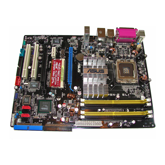
Page 23: Motherboard Layout
650i SLI CHA_FAN1 AUDIO CR2032 3V Lithium Cell CMOS Power Marvell PCIEX16_1 88E1116 SLI_CON Super I/O PCIEX1_2 NVIDIA nForce 430i PCIEX16_2 PCI1 VT6308P ALC883 BIOS USB78 PCI2 SB_PWR CLRTC USBPW5-8 CHA_FAN2 COM1 IE1394_2 CHASSIS FLOPPY AAFP USB56 PANEL ASUS P5N-E SLI... -
Page 24: Central Processing Unit (Cpu)
Contact your retailer immediately if the PnP cap is missing, or if you see any damage to the PnP cap/socket contacts/motherboard components. ASUS will shoulder the cost of repair only if the damage is shipment/ transit-related. •... - Page 25 Alignment key Position the CPU over the socket, making sure that the gold triangle is on the bottom-left corner of the socket. The socket alignment CPU notch key should fit into the CPU notch. Gold triangle mark ASUS P5N-E SLI 1-11...
- Page 26 The CPU fits in only one correct orientation. DO NOT force the CPU into the socket to prevent bending the connectors on the socket and damaging the CPU! Close the load plate (A), then push the load lever (B) until it snaps into the retention tab.
-
Page 27: Installing The Cpu Heatsink And Fan
CPU fan connector. Motherboard hole Narrow end Fastener of the groove Make sure to orient each fastener with the narrow end of the groove pointing outward. (The photo shows the groove shaded for emphasis.) ASUS P5N-E SLI 1-13... - Page 28 Connect the CPU fan cable to the connector on the motherboard labeled CPU_FAN. CPU_FAN P5N-E SLI CPU Fan Connector • Do not forget to connect the CPU fan connector! Hardware monitoring errors can occur if you fail to plug this connector.
-
Page 29: Uninstalling The Cpu Heatsink And Fan
Rotate each fastener counterclockwise. Pull up two fasteners at a time in a diagonal sequence to disengage the heatsink and fan assembly from the motherboard. Carefully remove the heatsink and fan assembly from the motherboard. ASUS P5N-E SLI 1-15... - Page 30 Rotate each fastener clockwise to ensure correct orientation when reinstalling. Narrow end of the groove The narrow end of the groove should point outward after resetting. (The photo shows the groove shaded for emphasis.) Refer to the documentation in the boxed or stand-alone CPU fan package for detailed information on CPU fan installation.
-
Page 31: System Memory
240-pin footprint compared to the 184-pin DDR DIMM. DDR2 DIMMs are notched differently to prevent installation on a DDR DIMM socket. The figure illustrates the location of the DDR2 DIMM sockets: P5N-E SLI 240-pin DDR2 DIMM Sockets Channel Sockets... - Page 32 Note on memory limitations The motherboard can support up to 8 GB on the operating systems listed below. You may install a maximum of 2 GB DIMMs on each slot. 32-bit 64-bit ® ® Windows 2000 Advanced Server Windows Server Standard x64 Edition ®...
- Page 33 • • 1024MB Apacer AM4B5708GQJS7E AU01GE667C5KBGC • • • 512MB Kingmax KKEA88B4LAUG-29DX KLCC28F-A8KB5 • • 512MB Transcend E5108AE-6E-E TS64MLQ64V6J • • • 1024MB Transcend E5108AE-6E-E TS128MLQ64V6J • • • 512MB Super Talent Heat-Sink Package T6UA512C5 • ASUS P5N-E SLI 1-19...
- Page 34 T5UB1G8C4 • • • Visit the ASUS website (www.asus.com) for the latest QVL. Side(s): SS - Single-sided DS - Double-sided DIMM support: Supports one module inserted into either slot, in Single-channel memory configuration. Supports one pair of modules inserted into either the blue slots or the black slots as one pair of Dual-channel memory configuration.
-
Page 35: Installing A Dimm
DIMM. Support the DIMM lightly with your fingers when pressing the retaining clips. The DIMM might get damaged when it DDR2 DIMM notch flips out with extra force. Remove the DIMM from the socket. ASUS P5N-E SLI 1-21... -
Page 36: Expansion Slots
1.8 Expansion slots In the future, you may need to install expansion cards. The following sub-sections describe the slots and the expansion cards that they support. Make sure to unplug the power cord before adding or removing expansion cards. Failure to do so may cause you physical injury and damage motherboard components. -
Page 37: Interrupt Assignments
— — — — — — — — — — — — — — Onboard IDE controller shared — — — — — — — Onboard Audio controller shared — — — — — — — ASUS P5N-E SLI 1-23... -
Page 38: Pci Slots
1.8.4 PCI slots The PCI slots support cards such as a LAN card, SCSI card, USB card, and other cards that comply with PCI specifications. The figure shows a LAN card installed on a PCI slot. 1.8.5 PCI Express x1 slot This motherboard supports PCI Express x1 network cards, SCSI cards and other cards that comply with the PCI Express specifications. -
Page 39: Two Pci Express X16 Slots
SLI mode Qualified SLI-ready Qualified SLI-ready Dual Video graphics cards graphics card Cards Qualified PCIe x16 Qualified PCIe x8, x4, Multi-monitor, graphics card graphics card, x2, x1 RAID or LAN RAID or LAN card setup ASUS P5N-E SLI 1-25... -
Page 40: Clear Rtc Ram
Removing the cap will cause system boot failure! CLRTC Normal Clear RTC (Default) P5N-E SLI Clear RTC RAM • Make sure to re-enter your previous BIOS settings after you clear the CMOS. • You do not need to clear the RTC when the system hangs due to overclocking. - Page 41 S3 and S4 sleep modes (no power to CPU, DRAM in slow refresh, power supply in reduced power mode). USBPW1-4 USBPW5-8 P5N-E SLI USB Device Wake Up • The USB device wake-up feature requires a power supply that can provide 500mA on the +5VSB lead for each USB port; otherwise, the system would not power up.
-
Page 42: 1.10 Connectors
1.10 Connectors 1.10.1 Rear panel connectors PS/2 mouse port (green). This port is for a PS/2 mouse. Parallel port. This 25-pin port connects a parallel printer, a scanner, or other devices. IEEE 1394a port. This 6-pin IEEE 1394 port provides high-speed connectivity for audio/video devices, storage peripherals, PCs, or portable devices. -
Page 43: 1.10.2 Internal Connectors
Pin 5 on the connector is removed to prevent incorrect cable connection when using a FDD cable with a covered Pin 5. FLOPPY PIN1 NOTE: Orient the red markings on the floppy ribbon cable to PIN 1. Floppy Disk Drive Connector P5N-E SLI ASUS P5N-E SLI 1-29... - Page 44 If any device jumper is set as “Cable-Select,” make sure all other device jumpers have the same setting. PIN1 NOTE: Orient the red markings (usually zigzag) on the IDE ribbon cable to PIN 1. PIN1 P5N-E SLI IDE Connectors 1-30 Chapter 1: Product introduction...
- Page 45 Audio connectors (4-pin CD) These connectors allow you to receive stereo audio input from sound sources such as a CD-ROM, TV-tuner, or MPEG card. (black) Right Audio Channel Ground Ground Left Audio Channel P5N-E SLI Internal Audio Connector ASUS P5N-E SLI 1-31...
- Page 46 Never connect a 1394 cable to the USB connectors. Doing so will damage the motherboard! ASUS EZ selector card connector (144-pin SLI_CON) This connector is for the ASUS proprietary ASUS EZ selector card that allows you to set the SLI mode to either Single Video card or Dual Video cards.
-
Page 47: Cpu And Chassis Fan Connectors
Insufficient air flow inside the system may damage the motherboard components. These are not jumpers! Do not place jumper caps on the fan connectors! CPU_FAN CHA_FAN2 CHA_FAN1 P5N-E SLI Fan Connectors Only the CPU_FAN connector support the ASUS Q-Fan feature. ASUS P5N-E SLI 1-33... -
Page 48: Atx Power Connectors
+5 Volts +5V Standby +5 Volts Power OK -5 Volts Ground Ground +5 Volts Ground Ground Ground +5 Volts PSON# Ground Ground +3 Volts -12 Volts +3 Volts +3 Volts P5N-E SLI ATX Power Connector 1-34 Chapter 1: Product introduction... -
Page 49: Power Supply Requirements
(S/PDIF) port(s). Connect the S/PDIF Out module cable to this connector, then install the module to a slot opening at the back of the system chassis. SPDIFOUT SPDIF_OUT P5N-E SLI Digital Audio Connector The S/PDIF module is purchased separately. ASUS P5N-E SLI 1-35... -
Page 50: System Panel Connector (20-Pin Panel)
SPEAKER RESET IDE_LED PWRSW Requires an ATX power supply P5N-E SLI System Panel Connector The sytem panel connector is color-coded for easy connection. Refer to the connector description below for details. • System power LED (3-pin PLED) This 3-pin connector is for the system power LED. Connect the chassis power LED cable to this connector. - Page 51 Q-Connector (System panel) ASUS Q-Connector allows you to easily to connect the chassis front panel cables to the motherboard. Perform these steps to install ASUS Q- Connector. Step 1 Connect the front panel cables to their respective connectors on the ASUS Q-Connector.
- Page 52 1-38 Chapter 1: Product introduction...
- Page 53 This chapter tells how to change the system settings through the BIOS Setup menus. Detailed descriptions of the BIOS parameters are also provided. BIOS setup...
-
Page 54: Chapter 2: Bios Setup
ASUS CrashFree BIOS 2 (Updates the BIOS using a bootable floppy disk or the motherboard support CD when the BIOS file fails or gets corrupted.) ASUS EZ Flash 2 (Updates the BIOS using a floppy disk, USB Flash, or the motherboard support CD during POST.) ®... -
Page 55: Updating The Bios
The Basic Input/Output System (BIOS) can be updated using the AwardBIOS Flash Utility. Follow these instructions to update the BIOS using this utility. 1. Download the latest BIOS file from the ASUS web site. Rename the file to P5NESLI.BIN and save it to a floppy disk. - Page 56 Type the BIOS file name AwardBIOS Flash Utility for ASUS V1.08 in the File Name to (C) Phoenix Technologies Ltd. All Rights Reserved Program field, then For NF-KC804-P5NESLI-00 DATE: 03/25/2005 press <Enter>. Flash Type - SST 49LF004A/B /3.3V File Name to Program: P5NESLI.bin...
-
Page 57: Saving The Current Bios File
Make sure that the floppy disk has enough disk space to save the file. To save the current BIOS file using the AwardBIOS Flash Utility: Follow steps 1 to 6 of AwardBIOS Flash Utility for ASUS V1.08 the previous section. (C) Phoenix Technologies Ltd. All Rights Reserved... -
Page 58: Asus Crashfree Bios 2 Utility
2.1.4 ASUS CrashFree BIOS 2 utility The ASUS CrashFree BIOS 2 is an auto recovery tool that allows you to restore the BIOS file when it fails or gets corrupted during the updating process. You can update a corrupted BIOS file using the motherboard support CD or the floppy disk that contains the updated BIOS file. -
Page 59: Recovering The Bios From A Floppy Disk
Restart the system after the utility completes the updating process. The recovered BIOS may not be the latest BIOS version for this motherboard. Visit the ASUS website (www.asus.com) to download the latest BIOS file. ASUS P5N-E SLI... -
Page 60: Asus Ez Flash2 Utility
2.1.5 ASUS EZ Flash 2 utility The ASUS EZ Flash 2 feature allows you to update the BIOS without having to go through the long process of booting from a floppy disk and using a DOS-based utility. The EZ Flash 2 utility is built-in the BIOS chip so it is accessible by pressing <Alt>... -
Page 61: Asus Update Utility
2.1.6 ASUS Update utility The ASUS Update is a utility that allows you to manage, save, and update ® the motherboard BIOS in Windows environment. The ASUS Update utility allows you to: • Save the current BIOS file • Download the latest BIOS file from the Internet •... -
Page 62: Updating The Bios Through The Internet
To update the BIOS through the Internet: ® Launch the ASUS Update utility from the Windows desktop by clicking Start > Programs > ASUS > ASUSUpdate > ASUSUpdate. The ASUS Update main window appears. Select Update BIOS from Select the ASUS FTP site... -
Page 63: Updating The Bios Through A Bios File
To update the BIOS through a BIOS file: ® Launch the ASUS Update utility from the Windows desktop by clicking Start > Programs > ASUS > ASUSUpdate > ASUSUpdate. The ASUS Update main window appears. Select Update BIOS from a file option from the drop-down menu, then click Next. -
Page 64: Bios Setup Program
The BIOS setup screens shown in this section are for reference purposes only, and may not exactly match what you see on your screen. • Visit the ASUS website (www.asus.com) to download the latest BIOS file for this motherboard. 2-12 Chapter 2: BIOS setup... -
Page 65: Bios Menu Screen
The BIOS setup screens shown in this chapter are for reference purposes only, and may not exactly match what you see on your screen. • Visit the ASUS website (www.asus.com) to download the latest BIOS information. ASUS P5N-E SLI 2-13... -
Page 66: Legend Bar
2.2.3 Legend bar At the bottom of the Setup screen is a legend bar. The keys in the legend bar allow you to navigate through the various setup menus. The following table lists the keys found in the legend bar with their corresponding functions. -
Page 67: Pop-Up Window
F5: Setup Defaults ESC: Exit →← : Select Menu Enter: Select Sub-menu F10: Save and Exit Pop-up menu 2.2.8 General help At the top right corner of the menu screen is a brief description of the selected item. ASUS P5N-E SLI 2-15... -
Page 68: Main Menu
2.3 Main menu When you enter the BIOS Setup program, the Main menu screen appears, giving you an overview of the basic system information. Refer to section “2.2.1 BIOS menu screen” for information on the menu screen items and how to navigate through them. Phoenix-Award BIOS CMOS Setup Utility Main Advanced... -
Page 69: Primary And Secondary Ide Master/Slave
If the hard disk was already formatted on a previous system, the setup BIOS may detect incorrect parameters. Select [Manual] to manually enter the IDE hard disk drive parameters. If no drive is installed select [None]. Configuration options: [None] [Auto] [Manual] ASUS P5N-E SLI 2-17... - Page 70 Access Mode [Auto] The default [Auto] allows automatic detection of an IDE hard disk drive. Select [CHS] for this item if you set the IDE Primary Master/Slave to [Manual]. Configuration options: [CHS] [LBA] [Large] [Auto] Before attempting to configure a hard disk drive, make sure you have the correct configuration information supplied by the drive manufacturer.
-
Page 71: Sata 1-4
Displays the auto-detected hard disk capacity. This item is not configurable. Cylinder Shows the number of the hard disk cylinders. This item is not configurable. Head Shows the number of the hard disk read/write heads. This item is not configurable. ASUS P5N-E SLI 2-19... -
Page 72: Hdd Smart Monitoring
Landing Zone Shows the number of landing zone per track. This item is not configurable. Sector Shows the number of sectors per track. This item is not configurable. After entering the IDE hard disk drive information into BIOS, use a disk utility, such as FDISK, to partition and format new IDE hard disk drives. -
Page 73: Advanced Menu
Manual Allows you to individually set overclocking parameters. Auto Loads the optimal settings for the system. Standard Loads the standard settings for the system. AI Overclock Loads overclocking profiles with optimal parameters for stability when overclocking. ASUS P5N-E SLI 2-21... -
Page 74: System Clocks
Overclock Options [Disabled] Allows you to disable or set the overclocking options. Configuration options: [Disabled] [Overclock 5%] [Overclock 10%] [Overclock 15%] [Overclock 20%] The Overclock Options item is user-configurable only when the AI Tuning is set to [AI Overclock]. System Clocks This sub-menu allows you to set PCI Express related field. -
Page 75: Voltage Control
[1.06875V] [1.06250V] [1.05625V] [1.05000V] [1.04375V] [1.03750V] [1.03125V] [1.02500V] [1.01875V] [1.01250V] [1.00625V] [1.00000V] [0.99375V] [0.98750V] [0.98125V] [0.97500V] [0.96875V] [0.96250V] [0.95625V] [0.95000V] [0.94375V] [0.93750V] [0.93125V] [0.92500V] [0.91875V] [0.91250V] [0.90625V] [0.90000V] [0.89375V] [0.88750V] [0.88125V] [0.87500V] [0.86875V] [0.86250V] [0.85625V] [0.85000V] [0.84375V] [0.83750V] [0.83125V] ASUS P5N-E SLI 2-23... -
Page 76: Fsb & Memory Config
Memory Voltage [Auto] Allows you to set the memory operating voltage. Set to Auto for safe mode. Configuration options: [Auto] [1.920V] [2.013V] [2.085V] [2.178V] [2.259V] [2.353V] [2.424V] [2.517V] Refer to the DDR2 documentation before setting the memory voltage. Setting a very high memory voltage may damage the memory module(s)! NB Core Voltage [Auto] Allows you to set the NB core voltage. -
Page 77: Ai Net2
-/+: Change Value F5: Setup Defaults ESC: Exit →← : Select Menu Enter: Select Sub-menu F10: Save and Exit POST Check LAN Cable [Disabled] Enables or disables LAN cable check during POST. Configuration options: [Disabled] [Enabled] ASUS P5N-E SLI 2-25... -
Page 78: Cpu Configuration
2.4.3 CPU Configuration Phoenix-Award BIOS CMOS Setup Utility Advanced CPU Configuration Select Menu Item Specific Help CPU Type Genuine Intel(R) CPU CPU Speed 2.80GHz Cache RAM 2048K DRAM timing and CPU Multiplier control CPU Core Unlock [Disabled] CPU Internal Thermal Control [Auto] Limit CPUID MaxVal [Disabled]... -
Page 79: Chipset
Spread Spectrum Control SLI Broadcast Aperture [Disabled] Press [Enter] to set. LDT Frequency [5x] F1:Help ↑↓ : Select Item -/+: Change Value F5: Setup Defaults ESC: Exit →← : Select Menu Enter: Select Sub-menu F10: Save and Exit ASUS P5N-E SLI 2-27... -
Page 80: Memory Timing Setting
Memory Timing Setting Phoenix-Award BIOS CMOS Setup Utility Advanced Memory Timing Setting Select Menu tCL (CAS Latency) [Auto] Item Specific Help tRCD [Auto] [Auto] Select [Expert] to tRAS [Auto] enter timings manually Command Per Clock (CMD) [Auto] ** Advanced Memory Settings ** tRRD [Auto] [Auto]... -
Page 81: Spread Spectrum Control
PCIE Spread Spectrum [Down Spread] SATA Spread Spectrum [Disabled] LDT Spread Spectrum [Disabled] ↑↓ : Select Item F1:Help -/+: Change Value F5: Setup Defaults →←: Select Menu ESC: Exit Enter: Select Sub-menu F10: Save and Exit ASUS P5N-E SLI 2-29... - Page 82 CPU Spread Spectrum [Disabled] Enables or disables CPU Spread Spectrum. Configuration options: [Disabled] [Auto] PCIE Spread Spectrum [Down Spread] Enables or disables PCIE Spread Spectrum. Configuration options: [Disabled] [Down Spread] SATA Spread Spectrum [Disabled] Enables or disables SATA Spread Spectrum. Configuration options: [Disabled] [Auto] LDT Spread Spectrum [Disabled] Enables or disables LDT Spread Spectrum.
-
Page 83: Pcipnp
Parallel Port Address [378/IRQ7] Parallel Port Mode [EPP] ECP Mode Use DMA F1:Help ↑↓ : Select Item -/+: Change Value F5: Setup Defaults ESC: Exit →← : Select Menu Enter: Select Sub-menu F10: Save and Exit ASUS P5N-E SLI 2-31... -
Page 84: Ide Function Setup
IDE Function Setup This sub-menu contains IDE function-related items. Select an item then press <Enter> to edit. Phoenix-Award BIOS CMOS Setup Utility Advanced IDE Function Setup Select Menu OnChip IDE Channel0 [Enabled] Item Specific Help OnChip IDE Channel1 [Enabled] IDE DMA transfer access [Enabled] Disable/Enable OnChip SATA Port 1, 2... -
Page 85: Nvraid Configuration
Allows you to disable or enabled the onboard HD audio controller. Configuration options: [Disabled] [Enabled] Front Panel Support Type [AC97] Allows you to select the Front Panel Type AC97 or HD Audio. Configuration options: [AC97] [HD Audio] ASUS P5N-E SLI 2-33... - Page 86 Onboard nVidia LAN [Enabled] Enables or disables the onboard NVIDIA® Gigabit LAN controller. Configuration options: [Disabled] [Enabled] OnBoard LAN Boot ROM [Disabled] Allows you to enable or disable the onboard NVIDIA® LAN boot ROM. Configuration options: [Enabled] [Disabled] Onboard 1394 [Enabled] Enables or disables the onboard 1394 device support.
-
Page 87: Usb Configuration
Allows you to enable or disable support for USB devices on legacy operating systems (OS). Configuration options: [Disabled] [Enabled] USB 2.0 Controller [Enabled] Allows you to enable or disable the USB 2.0 controller. Configuration options: [Disabled] [Enabled] ASUS P5N-E SLI 2-35... -
Page 88: Power Menu
2.5 Power menu The Power menu items allow you to change the settings for the Advanced Configuration and Power Interface (ACPI) and the Advanced Power Management (APM). Select an item then press <Enter> to display the configuration options. Phoenix-Award BIOS CMOS Setup Utility Main Advanced Power... -
Page 89: Apm Configuration
Thus, connection cannot be made on the first try. Turning an external modem off and then back on while the computer is off causes an initialization string that turns the system power on. ASUS P5N-E SLI 2-37... - Page 90 Power On By RTC Alarm [Disabled] Allows you to enable or disable RTC to generate a wake event. When this item is set to Enabled, the items Date of Month Alarm and Time (hh:mm:ss) Alarm items become user-configurable with set values. Configuration options: [Disabled] [Enabled] Date (of Month) Alarm [Disabled] To set the date of alarm, highlight this item and press <Enter>...
-
Page 91: Hardware Monitor
Allows you to enable or disable the ASUS Q-Fan feature. Configuration options: [Disabled] [Enabled] Chassis Q-Fan Controller [Disabled] Allows you to enable or disable the ASUS Chassis Q-Fan feature. Configuration options: [Disabled] [Enabled] VCORE Voltage, +3.3V Voltage, 5V Voltage, 12V Voltage The onboard hardware monitor automatically detects the voltage output through the onboard voltage regulators. -
Page 92: Boot Menu
2.6 Boot menu The Boot menu items allow you to change the system boot options. Select an item then press <Enter> to display the sub-menu. Phoenix-Award BIOS CMOS Setup Utility Main Advanced Power Boot Tools Exit Select Menu Boot Device Priority Removable Drives Item Specific Help Boot Settings Configuration... -
Page 93: Removable Drives
→← : Select Menu Enter: Select Sub-menu F10: Save and Exit Quick Boot [Enabled] Allows you to enable or disable the system quick boot feature. When Enabled, the system skips certain tests while booting. Configuration options: [Disabled] [Enabled] ASUS P5N-E SLI 2-41... - Page 94 Allows you to enable or disable the full screen logo display feature. Configuration options: [Disabled] [Enabled] Make sure that the above item is set to [Enabled] if you want to use the ASUS MyLogo2™ feature. Halt On [All Errors] Allows you to error report type.
-
Page 95: Security
To clear the password: Select the password field and press <Enter> twice. The following message appears: PASSWORD DISABLED !!! Press any key to continue... Press any key to continue. The password field setting is changed to Clear. ASUS P5N-E SLI 2-43... -
Page 96: Tools Menu
<Enter> to display the sub-menu. Phoenix-Award BIOS CMOS Setup Utility Main Advanced Power Boot Tools Exit ASUS O.C. Profile Select Menu ASUS EZ Flash 2 Item Specific Help ↑↓ : Select Item F1:Help -/+: Change Value 2-44 Chapter 2: BIOS setup... -
Page 97: Asus O.c. Profile
4. Press <Tab> to select the drive with the BIOS profile then press <Enter>to load file. 5. Follow message screen when loading is finished. Update only a BIOS file coming from the same memory/CPU configuration and BIOS version. ASUS P5N-E SLI 2-45... -
Page 98: Save Bios Profile
Save BIOS Profile Phoenix-Award BIOS CMOS Setup Utility Tools Save BIOS Profile Select Menu Item Specific Help Save to Profile 1 Save to Profile 2 Save current BIOS Profile Save to File to Profile 1. Save to Profile 1/2 Allows you to save the current BIOS file to the BIOS Flash. Press <Enter> to save the file. -
Page 99: Asus Ez Flash 2
2.7.2 ASUS EZ Flash 2 Allows you to run ASUS EZ Flash 2. Press <Enter> to start EZ Flash 2 then from the confirmation screen, use the left or right arrows to select [Yes] or [No] then press <Enter>. The following screen appears if you select [Yes]. Follow screen instructions to flash the BIOS. -
Page 100: Exit Menu
2.8 Exit menu The Exit menu items allow you to load the optimal or failsafe default values for the BIOS items, and save or discard your changes to the BIOS items. Phoenix-Award BIOS CMOS Setup Utility Main Advanced Power Boot Exit Exit &... -
Page 101: Load Setup Defaults
Discard Changes This option allows you to discard the selections you made and restore the previously saved values. After selecting this option, a confirmation appears. Select Yes to discard any changes and load the previously saved values. ASUS P5N-E SLI 2-49... - Page 102 2-50 Chapter 2: BIOS setup...
- Page 103 This chapter describes the contents of the support CD that comes with the motherboard package. Software support...
-
Page 104: Support Cd Information
The contents of the support CD are subject to change at any time without notice. Visit the ASUS website(www.asus.com) for updates. 3.2.1 Running the support CD Place the support CD to the optical drive. -
Page 105: Drivers Menu
The drivers menu shows the available device drivers if the system detects installed devices. Install the necessary drivers to activate the devices. ASUS InstAll-Drivers Installation Wizard Installs all of the drivers through ASUS InstAll-Installation wizard. nVidia Chipset Driver Program Installs the NVIDIA Chipset drivers for the NVIDIA nForce™... -
Page 106: Utilities Menu
® and print documents in Portable Document Format (PDF). ASUS Update Allows you to download the latest version of the BIOS from the ASUS website. Before using the ASUS Update, make sure that you have an Internet connection so you can connect to the ASUS website. -
Page 107: Make Disk Menu
SATA RAID driver disk. NVIDIA 32bit SATA RAID Driver Creates the NVIDIA 32bit driver disk for Serial ATA RAID features. ® NVIDIA 64bit SATA RAID Driver Creates the NVIDIA 64bit driver disk for Serial ATA RAID features. ® ASUS P5N-E SLI... -
Page 108: Manuals Menu
JMicron JMB36X 32bit RAID Driver Creates the JMicron JMB36X 32bit RAID Driver. JMicron JMB36X 64bit RAID Driver Creates the JMicron JMB36X 64bit RAID Driver. 3.2.5 Manuals menu The Manuals menu contains a list of supplementary user manuals. Click an item to open the folder of the user manual. •... -
Page 109: Asus Contact Information
Allows you to open the JMicron JMB36X RAID BIOS User’s Manual. 3.2.6 ASUS Contact information Click the Contact tab to display the ASUS contact information. You can also find this information on the inside front cover of this user guide. ASUS P5N-E SLI... -
Page 110: Nvidia ® Sli™ Technology
NVIDIA certified. ® • Visit the ASUS website (www.asus.com) for a list of qualified SLI-ready graphics cards for this motherboard. • Make sure that your graphics card driver supports the NVIDIA SLI technology. Download the latest driver from the NVIDIA website (www.nvidia.com). -
Page 111: 3.3.2 Dual Graphics Card Setup
Setting the ASUS EZ selector card Your motherboard package comes with a pre- installed ASUS EZ selector card. By default, the card is set for a single graphics card. To use two graphics cards on this motherboard, you must first set the selector card to Dual Video Cards. - Page 112 When released, pull the selector card out of the slot. Invert the selector card and insert the edge labeled Dual Video Cards. Push down the selector card until the retention clips snap into place. Make sure to completely insert the selector card into the slot. 3-10 Chapter 3: Software support...
- Page 113 Different types of graphics cards will not work together properly. To install the graphics cards: Prepare two graphics cards. Each graphics card should have goldfingers for the SLI connector. Goldfingers Remove the metal bracket covers opposite the two PCI Express x16 slots. ASUS P5N-E SLI 3-11...
- Page 114 Insert one graphics card into the blue slot labeled PCIEX16_1. Make sure that the card is properly seated on the slot. Insert the second graphics card into the black slot labeled PCIEX16_2. Make sure that the card is properly seated on the slot. If required, connect an auxiliary power source to the PCI Express graphics cards.
-
Page 115: Installing The Device Drivers
Refer to the documentation that came with your graphics card package to install the device drivers. Make sure that your PCI Express graphics card driver supports the NVIDIA SLI technology. Download the latest driver from the NVIDIA website (www.nvidia.com). ASUS P5N-E SLI 3-13... - Page 116 Enabling the multi-GPU feature in Windows After installing your graphics cards and the device drivers, enable the Multi-Graphics Processing Unit (GPU) feature in the NVIDIA nView properties. To enable the multi-GPU feature: Click the NVIDIA Settings icon on your Windows taskbar. NVIDIA Settings icon From the pop-up menu, select nView Desktop Manager then...
- Page 117 From the Display Properties dialog box, select the Settings tab then click Advanced. Select the NVIDIA GeForce tab. Click the slider to display the following screen, then select the SLI multi-GPU item. Slider ASUS P5N-E SLI 3-15...
-
Page 118: Creating A Raid Driver Disk
Click the Enable SLI multi-GPU check box. Click OK when done. 3.4 Creating a RAID driver disk A floppy disk with the RAID driver is required when installing Windows ® 2000/XP operating system on a hard disk drive that is included in a RAID set. - Page 119 The Appendix describes the CPU features that the motherboard supports. CPU features...
-
Page 120: Appendix: Cpu Features
32-bit operating systems. • The motherboard comes with a BIOS file that supports EM64T. You can download the latest BIOS file from the ASUS website (www.asus. com/support/download/) if you need to update the BIOS file. See Chapter 2 for details. -
Page 121: Using The Eist
Click Apply, then click OK. 10. Close the Display Properties window. After you adjust the power scheme, the CPU internal frequency slightly decreases when the CPU loading is low. The screen displays and procedures may vary depending on the operating system. ASUS P5N-E SLI... -
Page 122: Intel ® Hyper-Threading Technology
A.3 Intel Hyper-Threading Technology ® • The motherboard supports Intel Pentium 4 LGA775 processors ® ® with Hyper-Threading Technology. • Hyper-Threading Technology is supported under Windows XP/2003 ® Server and Linux 2.4.x (kernel) and later versions only. Under Linux, use the Hyper-Threading compiler to compile the code. If you are using any other operating systems, disable the Hyper-Threading Techonology item in the BIOS to ensure system stability and performance.