Table of Contents
Advertisement
Advertisement
Chapters
Table of Contents

Related Manuals for Asus P5KPL EPU


Summary of Contents for Asus P5KPL EPU
- Page 1 P5KPL/EPU...
- Page 2 Product warranty or service will not be extended if: (1) the product is repaired, modified or altered, unless such repair, modification of alteration is authorized in writing by ASUS; or (2) the serial number of the product is defaced or missing.
-
Page 3: Table Of Contents
Welcome! ..................1-1 Package contents ................. 1-1 Special features ................1-1 1.3.1 Product highlights ............1-1 1.3.2 Innovative ASUS features ..........1-2 Before you proceed ..............1-4 Motherboard overview ..............1-5 1.5.1 Placement direction ............1-5 1.5.2 Screw holes ..............1-5 1.5.3... - Page 4 Chapter 2: BIOS information Managing and updating your BIOS ..........2-1 2.1.1 ASUS Update utility ............2-1 2.1.2 ASUS EZ Flash 2 utility ........... 2-2 2.1.3 ASUS CrashFree BIOS 3 utility ........2-3 BIOS setup program ..............2-4 2.2.1 BIOS menu screen ............2-5 2.2.2...
- Page 5 Boot Device Priority ............2-17 2.6.2 Boot Settings Configuration .......... 2-17 2.6.3 Security ................. 2-18 Tools menu ................. 2-20 2.7.1 AI NET 2................ 2-20 2.7.2 ASUS EZ Flash 2 ............2-20 2.7.3 Express Gate ..............2-20 Exit menu ..................2-21...
-
Page 6: Notices
Complying with the REACH (Registration, Evaluation, Authorisation, and Restriction of Chemicals) regulatory framework, we published the chemical substances in our products at ASUS REACH website at http://green.asus.com/english/REACH.htm DO NOT throw the motherboard in municipal waste. This product has been designed to enable proper reuse of parts and recycling. -
Page 7: Safety Information
Safety information Electrical safety • To prevent electrical shock hazard, disconnect the power cable from the electrical outlet before relocating the system. • When adding or removing devices to or from the system, ensure that the power cables for the devices are unplugged before the signal cables are connected. If possible, disconnect all power cables from the existing system before you add a device. -
Page 8: Conventions Used In This Guide
Refer to the following sources for additional information and for product and software updates. ASUS websites The ASUS website provides updated information on ASUS hardware and software products. Refer to the ASUS contact information. Optional documentation Your product package may include optional documentation, such as warranty flyers, that may have been added by your dealer. -
Page 9: P5Kpl/Epu Specifications Summary
8 x USB 2.0/1.1 ports (4 ports at mid-board, 4-ports at back panel) ASUS exclusive SFS (Stepless Frequency Selection): overclocking features - FSB tuning from 133MHz to 600MHz at 1MHz increment Overclocking protection: - ASUS C.P.R. (CPU Parameter Recall) (continued on the next page) - Page 10 1 x CD audio-in connector 1 x IDE connector 1 x 24-pin EPS Power connector 1 x 4-pin ATX 12V Power connector ASUS Special features ASUS CrashFree BIOS 3 ASUS EZ Flash2 ASUS Express Gate ASUS EPU ASUS Q-Fan ASUS MyLogo 2...
-
Page 11: Chapter 1: Product Introduction
® The motherboard delivers a host of new features and latest technologies, making it another standout in the long line of ASUS quality motherboards! Before you start installing the motherboard, and hardware devices on it, check the items in your package with the list below. -
Page 12: Innovative Asus Features
1.3.2 Innovative ASUS features ASUS EPU ASUS EPU detects the current computer loading and intelligently adjusts the appropriate power usage in real-time. ASUS MyLogo2™ This feature allows you to convert your favorite photo into a 256-color boot logo for a more colorful and vivid image on your screen. -
Page 13: Express Gate
BIOS file using the bundled support DVD or USB disk that contains the latest BIOS file. ASUS EZ Flash 2 ASUS EZ Flash 2 is a utility that allows you to update the BIOS without using an OS-based utility. Express Gate... -
Page 14: Before You Proceed
Before you proceed Take note of the following precautions before you install motherboard components or change any motherboard settings. • Unplug the power cord from the wall socket before touching any component. • Before handling components, use a grounded wrist strap or touch a safely grounded object or a metal object, such as the power supply case, to avoid damaging them due to static electricity. -
Page 15: Motherboard Overview
Screw holes Place six screws into the holes indicated by circles to secure the motherboard to the chassis. Do not overtighten the screws! Doing so can damage the motherboard. Place this side towards the rear of the chassis ASUS P5KPL/EPU... -
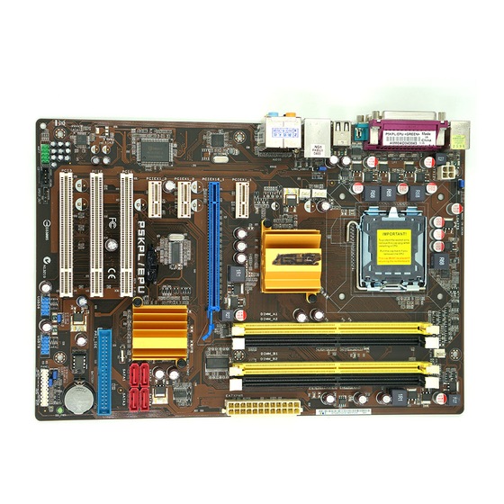
Page 16: Motherboard Layout
1.5.3 Motherboard layout 20.8cm(8.2in) 1.5.4 Layout contents Connectors/Jumpers/Slots Page Connectors/Jumpers/Slots Page Keyboard/mouse power (3-pin PS2 USBPW1-4) 1-21 Clear RTC RAM (3-pin CLRTC) 1-20 ATX power connectors (24-pin EATXPWR, 4-pin 1-24 System panel connector (20-8 pin PANEL) 1-27 ATX12V) CPU, chassis, and power fan connectors (4-pin 1-23 Chassis intrusion connector (4-1 pin 1-25... -
Page 17: Central Processing Unit (Cpu)
Contact your retailer immediately if the PnP cap is missing, or if you see any damage to the PnP cap/socket contacts/motherboard components. ASUS will shoulder the cost of repair only if the damage is shipment/transit-related. • Keep the cap after installing the motherboard. ASUS will process Return Merchandise Authorization (RMA) requests only if the motherboard comes with the cap on the LGA775 socket. - Page 18 Press the load lever with your thumb Retention tab (A), then move it to the left (B) until it is released from the retention tab. To prevent damage to the socket pins, do not remove the PnP cap unless you are installing a CPU. Load lever Lift the load lever in the direction of the PnP cap...
- Page 19 To prevent contaminating the paste, DO NOT spread the paste with your finger directly. Close the load plate (A), then push the load lever (B) until it snaps into the retention tab. ASUS P5KPL/EPU...
-
Page 20: Installing The Cpu Heatsink And Fan
1.6.2 Installing the CPU heatsink and fan The Intel LGA775 processor requires a specially designed heatsink and fan assembly to ® ensure optimum thermal condition and performance. • When you buy a boxed Intel processor, the package includes the CPU fan and ®... -
Page 21: Uninstalling The Cpu Heatsink And Fan
To uninstall the CPU heatsink and fan: Disconnect the CPU fan cable from the connector on the motherboard. Rotate each fastener counterclockwise. Pull up two fasteners at a time in a diagonal sequence to disengage the heatsink and fan assembly from the motherboard. ASUS P5KPL/EPU 1-11... -
Page 22: System Memory
Carefully remove the heatsink and fan assembly from the motherboard. Rotate each fastener clockwise to ensure correct orientation when reinstalling. System memory 1.7.1 Overview The motherboard comes with four Double Data Rate 2 (DDR2) Dual Inline Memory Modules (DIMM) sockets. The figure illustrates the location of the DDR2 DIMM sockets: Channel Sockets Channel A... -
Page 23: Memory Configurations
ODT value. • Due to chipset limitation, DDR2-800 with CL=4 will be downgraded to run at DDR2-667 by default setting. If you want to operate with lower latency, adjust the memory timing manually. ASUS P5KPL/EPU 1-13... - Page 24 P5KPL/EPU Motherboard Qualified Vendors Lists (QVL) DDR2-667 MHz capability DIMM support Vendor Part No. Size Chip Brand Chip NO. “Timing A-Data M2OAD5G314170Q1C58 1024MB ADATA AD29608A8A-3EG80814 • • A-Data M2OAD5H3J4170I1C53 2048MB ADATA AD20908A8A-3EG 30724 • • Apacer AM4B5808CQJS7E0749B 2048MB Apacer 78.A1G9O.9K4 •...
- Page 25 • B*: Supports one pair of modules inserted into either the yellow or black slots as one pair of Dual-channel memory configuration. • C*: Supports four modules inserted into both the yellow and black slots as two pairs of Dual-channel memory configuration. Visit the ASUS website at www.asus.com for the latest QVL. ASUS P5KPL/EPU 1-15...
-
Page 26: Installing A Dimm
1.7.3 Installing a DIMM Unplug the power supply before adding or removing DIMMs or other system components. Failure to do so can cause severe damage to both the motherboard and the components. To install a DIMM: DDR2 DIMM notch Press the retaining clips outward to unlock a DDR2 DIMM socket. -
Page 27: Expansion Slots
This motherboard supports PCI Express x1 network cards, SCSI cards, and other cards that comply with the PCI Express specifications. 1.8.5 PCI Express x16 slot This motherboard supports a PCI Express x16 graphics card that complies with the PCI Express specifications. ASUS P5KPL/EPU 1-17... -
Page 28: Jumpers
Jumpers Clear RTC RAM (3-pin CLRTC) This jumper allows you to clear the Real Time Clock (RTC) RAM in CMOS. You can clear the CMOS memory of date, time, and system setup parameters by erasing the CMOS RTC RAM data. The onboard button cell battery powers the RAM data in CMOS, which include system setup information such as system passwords. -
Page 29: Keyboard/Mouse Power (3-Pin Ps2 Usbpw1-4)
Set to +5VSB to wake up from S3 and S4 sleep modes (no power to CPU, DRAM in slow refresh, power supply in reduced power mode). This jumper is for the internal USB connectors that you can connect to additional USB ports. ASUS P5KPL/EPU 1-19... -
Page 30: Connectors
1.10 Connectors 1.10.1 Rear panel connectors 4 5 6 7 PS/2 mouse port (green). This port is for a PS/2 mouse. Parallel port. This 25-pin port connects a parallel printer, a scanner, or other devices. LAN (RJ-45) port. This port allows Gigabit connection to a Local Area Network (LAN) through a network hub. -
Page 31: Internal Connectors
Do not forget to connect the fan cables to the fan connectors. Insufficient air flow inside the system may damage the motherboard components. These are not jumpers! Do not place jumper caps on the fan connectors! Only the CPU fan supports the ASUS Q-FAN feature. ASUS P5KPL/EPU 1-21... -
Page 32: Atx Power Connectors
ATX power connectors (24-pin EATXPWR, 4-pin ATX12V) These connectors are for ATX power supply plugs. The power supply plugs are designed to fit these connectors in only one orientation. Find the proper orientation and push down firmly until the connectors completely fit. •... -
Page 33: Serial Ata Connectors (7-Pin Sata1-4)
The signal is then generated as a chassis intrusion event. By default, the pin labeled “Chassis Signal” and “Ground” are shorted with a jumper cap. Remove the jumper caps only when you intend to use the chassis intrusion detection feature. ASUS P5KPL/EPU 1-23... - Page 34 IDE connector (40-1 pin PRI_EIDE) The onboard IDE connector is for the Ultra DMA 100/66 signal cable. There are three connectors on each Ultra DMA 100/66 signal cable: blue, black, and gray. Connect the blue connector to the motherboard’s IDE connector, then select one of the following modes to configure your device.
-
Page 35: System Panel Connector (20-8 Pin Panel)
Pressing the power switch for more than four seconds while the system is ON turns the system OFF. • Reset button (2-pin RESET) This 2-pin connector is for the chassis-mounted reset button for system reboot without turning off the system power. ASUS P5KPL/EPU 1-25... -
Page 36: Usb Connectors (10-1 Pin Usb56 And Usb78)
Never connect a 1394 cable to the USB connectors. Doing so will damage the motherboard! You can connect the front panel USB cable to the ASUS Q-Connector (USB, blue) first, and then install the Q-Connector (USB) to the USB connector onboard if your chassis supports front panel USB ports. -
Page 37: Digital Audio Connector
The S/PDIF module is purchased separately. Optical drive audio connector (4-pin CD) These connectors allow you to receive stereo audio input from sound sources such as a CD-ROM, TV tuner, or MPEG card. ASUS P5KPL/EPU 1-27... -
Page 38: Front Panel Audio Connector
Front panel audio connector (10-1 pin AAFP) This connector is for a chassis-mounted front panel audio I/O module that supports either HD Audio or legacy AC`97 audio standard. Connect one end of the front panel audio I/O module cable to this connector. •... -
Page 39: Software Support
Click an item to install If Autorun is NOT enabled in your computer, browse the contents of the Support DVD to locate the file ASSETUP.EXE from the BIN folder. Double-click the ASSETUP.EXE to run the DVD. ASUS P5KPL/EPU 1-29... - Page 40 1-30 Chapter 1: Product introduction...
-
Page 41: Managing And Updating Your Bios
BIOS in the future. Copy the original motherboard BIOS using the ASUS Update. 2.1.1 ASUS Update utility The ASUS Update is a utility that allows you to manage, save, and update the motherboard BIOS in Windows environment. ®... -
Page 42: Asus Ez Flash 2 Utility
Follow the onscreen instructions to complete the updating process. 2.1.2 ASUS EZ Flash 2 utility The ASUS EZ Flash 2 feature allows you to update the BIOS without using an OS-based utility. Before you start using this utility, download the latest BIOS file from the ASUS website at www.asus.com. -
Page 43: Asus Crashfree Bios 3 Utility
2.1.3 ASUS CrashFree BIOS 3 utility The ASUS CrashFree BIOS 3 is an auto recovery tool that allows you to restore the BIOS file when it fails or gets corrupted during the updating process. You can update a corrupted BIOS file using the motherboard support DVD or a USB flash disk that contains the updated BIOS file. -
Page 44: Bios Setup Program
Restart the system after the utility completes the updating process. • Only a USB flash disk with FAT 32/16 format and single partition can support ASUS CrashFree BIOS 3. The device size should be smaller than 8GB. • DO NOT shut down or reset the system while updating the BIOS! Doing so can cause system boot failure! The recovered BIOS may not be the latest BIOS version for this motherboard. -
Page 45: Bios Menu Screen
• The BIOS setup screens shown in this section are for reference purposes only, and may not exactly match what you see on your screen. • Visit the ASUS website at www.asus.com to download the latest BIOS file for this motherboard. -
Page 46: Navigation Keys
2.2.3 Navigation keys At the bottom right corner of a menu screen are the navigation keys for that particular menu. Use the navigation keys to select items in the menu and change the settings. Some of the navigation keys differ from one screen to another. 2.2.4 Menu items The highlighted item on the menu bar displays the specific items for that menu. -
Page 47: Main Menu
IDE/SATA device type. Select [CDROM] if you are specifically configuring a CD- ROM drive. Select [ARMD] (ATAPI Removable Media Device) if your device is either a ZIP, LS-120, or MO drive. Configuration options: [Not Installed] [Auto] [CDROM] [ARMD] This item does appear when you select the SATA 1/2/3/4 devices. ASUS P5KPL/EPU... -
Page 48: Ide Configuration
LBA/Large Mode [Auto] Enables or disables the LBA mode. Setting to [Auto] enables the LBA mode if the device supports this mode, and if the device was not previously formatted with LBA mode disabled. Configuration options: [Disabled] [Auto] Block (Multi-sector Transfer) M [Auto] Enables or disables data multi-sectors transfers. -
Page 49: System Information
Select either one of the preset overclocking configuration options: Manual - allows you to individually set overclocking parameters. Auto - loads the optimal settings for the system. Overclock Profile - loads overclocking profiles with optimal parameters for stability when overclocking. ASUS P5KPL/EPU... - Page 50 The following item appears only when you set the AI Overclocking item to [Manual]. CPU Frequency [xxx] Displays the frequency sent by the clock generator to the system bus and PCI bus. The value of this item is auto-detected by the BIOS. Use the <+> and <-> keys to adjust the CPU frequency.
-
Page 51: Usb Configuration
USB support is disabled. Configuration options: [Disabled] [Enabled] [Auto] USB 2.0 Controller Mode [HiSpeed] Allows you to configure the USB 2.0 controller in HiSpeed (480Mbps) or Full Speed (12Mbps). Configuration options: [FullSpeed] [HiSpeed] ASUS P5KPL/EPU 2-11... -
Page 52: Cpu Configuration
The following item may only appear when a USB storage device is plugged. USB Mass Stroage Device Configuration USB Mass Stroage Reset Delay [20 Sec] Allows you to set the USB mass stroage reset delay. Configuration options: [10 Sec] [20 Sec] [30 Sec] [ 40 Sec] Emulation Type [Auto] Allows you to set the emulation type. -
Page 53: Chipset
Allows you to enable or disable the boot ROM in the onboard LAN controller. This item appears only when the Onboard LAN item is set to Enabled. Configuration options: [Disabled] [Enabled] Serial Port1 Address [3F8/IRQ4] Allows you to select the Serial Port1 base address. Configuration options: [Disabled] [3F8/IRQ4] [2F8/IRQ3] [3E8/IRQ4] [2E8/IRQ3] ASUS P5KPL/EPU 2-13... -
Page 54: Pci Pnp
Parallel Port Address [378] Allows you to select the Parallel Port base addresses. Configuration options: [Disabled] [378] [278] [3BC] Parallel Port Mode [ECP] Allows you to select the Parallel Port mode. Configuration options: [Normal] [Bi-Directional] [EPP] [ECP] ECP Mode DMA Channel [DMA3] Appears only when the Parallel Port Mode is set to [ECP]. -
Page 55: Power Menu
[Power On], the system goes on after an AC power loss. When set to [Last State], the system goes into either off or on state, whatever the system state was before the AC power loss. Configuration options: [Power Off] [Power On] [Last State] ASUS P5KPL/EPU 2-15... -
Page 56: Hardware Monitor
Resume On Ring [Disabled] Allows you to enable or disable RI to generate a wake event. Configuration options: [Disabled] [Enabled] Resume On PCI Devices [Disabled] When set to [Enabled], this parameter allows you to wake the system through a PCI LAN or modem card. -
Page 57: Boot Menu
POST items. Configuration options: [Disabled] [Enabled] Full Screen Logo [Enabled] This allows you to enable or disable the full screen logo display feature. Configuration options: [Disabled] [Enabled] Set this item to [Enabled] to use the ASUS MyLogo2 feature. ™ ASUS P5KPL/EPU... -
Page 58: Security
AddOn ROM Display Mode [Force BIOS] Sets the display mode for option ROM. Configuration options: [Force BIOS] [Keep Current] Bootup Num-Lock [On] Allows you to select the power-on state for the NumLock. Configuration options: [Off] [On] PS/2 Mouse Support [Auto] Allows you to enable or disable support for PS/2 mouse. -
Page 59: Change User Password
Password Check [Setup] When set to [Setup], BIOS checks for user password when accessing the Setup utility. When set to [Always], BIOS checks for user password both when accessing Setup and booting the system. Configuration options: [Setup] [Always] ASUS P5KPL/EPU 2-19... -
Page 60: Tools Menu
2.7.2 ASUS EZ Flash 2 Allows you to run ASUS EZ Flash 2. When you press <Enter>, a confirmation message appears. Use the left/right arrow key to select between [Yes] or [No], then press <Enter> to confirm your choice. Please see section 2.1.3 for details. -
Page 61: Exit Menu
When you select this option or if you press <F5>, a confirmation window appears. Select OK to load default values. Select Exit & Save Changes or make other changes before saving the values to the non-volatile RAM. ASUS P5KPL/EPU 2-21... - Page 62 2-22 Chapter 2: BIOS information...